1
LI-3000A Portable Area Meter
LI-3050A Belt Conveyer
Instruction
Manual
®
LI-3000A Portable Area Meter
LI-3050A Transparent Belt
Conveyer
Instruction Manual
Publication No. 8805-0055
June, 1988
LI-COR, inc.
4421 Superior Street
P.O. Box 4425
Lincoln, Nebraska 68504-0425 USA
Telephone: (402) 467-3576
FAX: 402-467-2819
Toll-free 1-800-447-3576 (U.S. & Canada)
IBM is a registered trademark of International Business Machines Corp.
PC-Talk is a trademark of Freeware.
ProComm is a trademark of Datastorm Technologies Inc.
Apple®, is a registered trademark and Macintosh* is a trademark licensed to Apple
Computer Inc.
NOTICE
The information contained in this document is subject to change without notice.
LI-COR MAKES NO WARRANTY OF ANY KIND WITH REGARD TO THIS
MATERIAL, INCLUDING, BUT NOT LIMITED TO THE IMPLIED
WARRANTIES OF MERCHANTABILITY AND FITNESS FOR A
PARTICULAR PURPOSE. LI-COR shall not be liable for errors contained herein
or for incidental or consequential damages in connection with the furnishing,
performance, or use of this material.
This document contains proprietary information which is protected by copyright.
All rights are reserved. No part of this document may be photocopied, reproduced,
or translated to another language without prior written consent of LI-COR, Inc.
© Copyright 1988, LI-COR, Inc.
i
How to Use This Manual
This manual contains the operation instructions for both the LI-3000A
Portable Area Meter and the LI-3050A Transparent Belt Conveyer
Accessory. If you purchased an LI-3000A but not an LI-3050A, you may
wish to skip Section VI which contains information on the LI-3050A.
If you already own an LI-3000A and have purchased only an LI-3050A, you
will want to skip directly to Section VI which has the LI-3050A operation
instructions.
If you want to operate the LI-3000A console with an LI-3100 Area Meter
you will want to read Section IV to learn how to connect the LI-3000A to
the LI-3100 and then read Section III for instrument operation instructions.
If you have purchased the 3000A-01 Readout Console to upgrade an older
LI-3000A Portable Area Meter, you will want to read Sections II and III. If
your sensor head has not been calibrated to your console you should also
read the sensor head calibration information in Section V.
Printing History
New editions of this manuals will incorporate all material since the previous edition.
The manual printing date indicates its current edition. The printing date changes
when a new edition is printed. (Minor corrections and updates which are
incorporated at reprint do not cause the date to change.)
Edition 1 - June 1988
ii
Table of Contents
SECTION I. General Information
System Description ...............................................................................
Theory of Operation ..............................................................................
Instrument Calibration ..........................................................................
1-1
1-2
1-3
SECTION II. Preoperation Procedures
Operational Check.................................................................................
Recharging the Battery ..........................................................................
Using the Waist Strap............................................................................
2-1
2-2
2-3
SECTION III. Instrument Operation
Power On............................................................................................... 3-1
Basic Operation ..................................................................................... 3-1
Making Measurements .......................................................................... 3-5
Storing Data In Memory ....................................................................... 3-10
Menu Key Routines .............................................................................. 3-16
Data Communications ........................................................................... 3-21
SECTION IV. Operation with the LI-3100 Area Meter
Operation with the LI-3100 Area Meter ...............................................
iii
4-1
SECTION V. Maintenance
Cleaning the LED and Photodiode Windows .......................................
Cleaning the Length Encoding Cord Guide ..........................................
Length Encoding Cord ..........................................................................
Knob Separation from the Length Encoding Cord................................
Battery Replacement .............................................................................
Internal Fuse ..........................................................................................
Instrument Storage ................................................................................
Test Menu..............................................................................................
5-1
5-1
5-1
5-2
5-2
5-3
5-4
5-4
SECTION VI. LI-3050A Transparent Belt Conveyer
Setup and Adjustment ...........................................................................
Storage and Maintenance ......................................................................
6-1
6-3
APPENDIX
APPENDIX A. LI-3000A Specifications ............................................
APPENDIX B. LI-3050A Specifications.............................................
WARRANTY
OBTAINING SERVICE FOR YOUR INSTRUMENT
iv
A-1
A-2
Section I
General Information
System Description
The LI-COR Model LI-3000A Portable Area Meter utilizes an electronic
method of rectangular approximation to measure leaf area on intact plants of
many species. The LI-3000A has two components, the Scanning Head and
the Readout Console. Area data is logged by the Readout Console as the
Scanning Head is passed over the leaf.
The LI-3000A console replaces the LI-3000 Portable Area Meter readout
console. The scanning heads on both instruments are the same. The
LI-3000A has the following features:
•
•
•
•
•
•
Displays leaf length, average width, and maximum width in addition to
area and accumulated area.
Readings can be summed in a secondary summing register at the user's
command. The previous reading added to the register can be subtracted
from it.
Readings can be stored in the console, and later output to a computer or
printer (RS-232C interface).
The console can be connected to any LI-3000 Portable Area Meter
scanning head. The console will self-calibrate heads with serial
numbers 197 and above. Heads with serial numbers PAM196 and
below require a specially configured console which does not
self-calibrate.
The console can be used with either the LI-3050A Transparent Belt
Conveyer Accessory, or the LI-3100 Area Meter (requires a minor
modification of LI-3100's with serial numbers LAM652 and below).
A rechargeable sealed lead acid battery provides power for portable
operation. The battery life is approximately 15 hours.
The LI-3000A has been designed for field use. Operate and store it with
care similar to that required for a camera. The 3000A-02 Carrying Case is
recommended.
The optional accessories for the LI-3000A include the 3000A-02 Carrying
Case, the LI-3050A Transparent Belt Conveyer Accessory, the 3000A-03
Interface Cable (for LI-3100 to LI-3000A), the 6000-03B RS-232C printer,
1-1
General Information
and the 3000A/SM Service Manual. Replacement and service items are
listed in Section V.
Theory of Operation
The method by which the LI-3000A measures area is best understood by
examining the technique for manual area measurement. Manual area
measurement requires tracing the outline of the sample on graph paper and
methodically counting the squares where the sample covers fifty percent or
more of the area of an individual grid cell.
The 50% criterion for the acceptance or rejection of grid cells is necessary
to maintain linearity in the measured area. In other words, if the grid cells
with fifty percent or more area covered were not counted, the result would
be inconsistent data on repeated measurements. Similarly, if a sample were
cut into pieces and the individual pieces summed, the results would likely
not equal the measurement of the whole sample (unless the 50% criterion
was used).
The width of the sample at a given point is determined by the number of
grid cells covered across a row. The number of grid cells covered in a
column determines the length. The resolution of this measurement
technique is a function of the area represented by each grid cell.
The function of the LI-3000A Portable Area Meter is to use electronic
methods to simulate a grid pattern on the leaf. The scanning head uses a
row of 128 narrow band, red, light-emitting diodes (LEDs), spaced on 1 mm
centers, to examine 128 grid cells across the width of the leaf. The LEDs are
sequentially pulsed (only one LED is lit at a time) to examine a particular
grid cell in the row. The LEDs are located along a line 0.62 cm (0.25 in.)
from the edge of the upper section of the scanning head.
The base of the scanning head contains a lens-photodiode system which
responds only to the collimated, pulsed LED light. This design makes the
measurements insensitive to other light sources. These narrow-band red
LEDs and associated digital circuitry provide measurements which are
unaffected by leaf transmission properties.
After each grid cell in the row is scanned, it is necessary to advance to the
next row. Electronically, this is accomplished by pulling the length
encoding cord. After each 1 mm of cord travel, a new scan is initiated in
which each of the 128 LEDs are sequentially pulsed. The scanning process
begins only when the length encoding cord is pulled.
1-2
General Information
Since 1 mm of cord travel is equivalent to the side of a grid cell, it is
apparent that the length encoding cord must be pulled perpendicular to the
row of 128 LEDs.
When the LED light is blocked by a sample, the unit area (1 mm2 ) is
accumulated on the display. For example, if a 20 × 100 mm sample is being
measured, 20 LEDs will be masked for 100 scans resulting in a display of
20.00 cm2 .
LEDs which are only partially blocked are also accounted for. The
calibration adjustment potentiometer (CAL ADJ) on the side of the console
is adjusted at the factory so that 1 mm2 of area is accumulated on the
display when the LED light is diminished by 50% or more.
The scanning head accurately measures irregularly shaped leaves or leaves
with holes from insect damage. As a hole in the leaf passes through the
scanning head, the photodiodes sense LED light, and that LED location
does not contribute to the area accumulating on the display until the LEDs
are once again masked when the hole has passed.
The important aspect of this electronic measurement technique is that it
requires that the light emitted from each of the 128 LEDs be uniform in
intensity so that the 50% acceptance/rejection threshold is consistent for
each grid cell. This is accomplished by the autocalibration software during
the calibration process.
Instrument Calibration
The scanning head is calibrated to the readout console at the factory using
the LI-3000A's built-in autocalibration routine (Section V). If a different
scanning head is to be used, the autocalibration routine must be performed
to calibrate the head to the console. The autocalibration routine computes
how much current each of the 128 LEDs requires in order to achieve a
constant brightness. These calibration values are retained as a table in the
memory of the console.
1-3
General Information
IMPORTANT:
Scanning heads with serial numbers PAM196 and below require a
specially configured LI-3000A. Consoles so configured should NEVER be used with heads
having serial numbers PAM197 and above. Damage to these heads could result. Similarly,
standard consoles should NEVER be used on heads with serial numbers PAM196 and below.
The only exception to this is if the area meter head with serial number PAM196 or below has
been updated by LI-COR. It would then be treated as having a serial number greater than
PAM196 and could then be used on a standard console.
THE CAL ADJUST POTENTIOMETER
The calibration accuracy is effected by the "CAL ADJ" potentiometer as
described in the theory section. This potentiometer is adjusted at the factory
to provide ± 2% accuracy for measurements with the scanning head, or the
scanning head with a transparent sheath. The "CAL ADJ" potentiometer
is adjusted by the user only when the LI-3000A is used with the
LI-3050A Transparent Belt Conveyer Accessory. This adjustment is
discussed in Section VI.
If the "CAL ADJ" potentiometer has been adjusted for use with the
LI-3050A, and it is also desired to use the LI-3000A in a portable mode
(without the LI-3050A), it is not necessary to adjust the CAL ADJ
potentiometer. For a typical scanning head, the accuracy difference
between the factory setting of the CAL ADJ potentiometer and the adjusted
setting used for the LI-3050A will introduce an error of 0.4 to 0.6%. The
measurement errors ( ± 2% accuracy) in portable mode are much more
significant. (Measurement errors in portable mode include not pulling the
length encoding cord perpendicular to the line of LEDs, and the error
introduced by not measuring the portion of the leaf that is between the edge
of the scanning head and the row of LEDs.)
1-4
Section II
Preoperation Procedures
Operational Check
The following procedure can be used to connect the scanning head to the
readout console and verify that the LI-3000A is working properly.
1) Connect the scanning head to the readout console while the ON/OFF
switch is OFF, and then switch the ON/OFF switch to ON.
A start-up message (Section III) indicates which scanning head is
calibrated to the console. If the scanning head serial number does not
match the serial number given in the start-up message you will need to
calibrate that head to the readout console using the built-in
autocalibration routine (Section VI).
If the symbol "Lo" appears on the display (see Recharging the Battery)
when the readout console is turned on, the internal battery needs
charging. The low battery message is displayed when 1 hour of
operational capacity remains in the battery. If your battery is low, skip
down to the information on recharging the battery found later in this
section.
If the message "CALIBRATION LOST PRESS ANY KEY" is displayed
when the instrument is turned on, the calibration table has been deleted
because of a power interruption to the memory (RAM). The scanning
head can be calibrated to the console as described in Section V.
2) Open the scanning head by pressing on the thumb lever which is part of
the upper section (Figure 2, Section III). Hold the scanning head
inverted and look into the long narrow window near the edge of the
head. Pull the length encoding cord out and retract it. You should be
able to see the LEDs as they rapidly pulse.
IMPORTANT: Retract the cord by holding the knob and allowing the
cord to draw into the head by its own force. The cord should not be
allowed to snap back into the head. Also, do not push the cord and
cause slack; internal backlash may result.
2-1
Preoperation Procedures
If you have been holding the head open while pulling the encoding cord,
you will notice that numbers are being accumulated on the display. This
is because the photodiodes will only accept the collimated light from the
LEDs when the components are positioned properly. This characteristic
was designed into the instrument to prevent stray light from affecting
normal data collection. With the scanning head open, the LEDs and the
photodiodes are out of alignment so area is recorded as the length
encoding cord is moved. If the cord is drawn or retracted at a rate
greater than 1 m/second, an error message is displayed as described in
Section III. (The error message can be cleared by pressing the CLEAR
X key.)
3) Clear any logged area data by pressing the white reset switch located on
the scanning head handle.
Recharging the Battery
The LI-3000A uses a sealed lead acid battery. This battery is rechargeable,
and gives about 15 hours of use. The symbol "Lo" appears on the display
(as shown below) when approximately 1 hour of battery life remains.
AREA
0 Lo
0.00
0.00
X
Y
After automatic shutdown, enough power remains in the battery to maintain
the memory for about 3 months. To prevent memory loss the battery
should be recharged every 3 months during storage.
To charge the battery, slide the voltage selector on the readout console
connector panel to the proper voltage. Connect the power cord to the
readout console and plug the cord into an AC source (115-230 VAC, 50-60
Hz).
The battery should normally be charged overnight. An automatic charging
cutoff is provided to prevent overcharging. The instrument may be operated
while it is charging; however, the time needed to fully recharge the battery
will be increased.
The LI-3000A's battery will not be harmed by continuous operation with
AC power.
There is no internal backup battery, so if the main battery is disconnected
for more than 20 seconds, all memory in the instrument will be cleared.
2-2
Preoperation Procedures
Using the Waist Strap
A waist strap has been provided so that the readout console can be worn
around the waist for portable operation. The waist strap is connected to the
console using the screws found on the right and left sides of the console.
For maximum comfort, the waist strap should be positioned so that the strap
is about the same level as a belt on a pair of pants. In this position the
weight of the console will rest on the pelvic bones and not on the "fleshy"
part of the back.
2-3
Section III
Instrument Operation
Power On
Before turning on the LI-3000A, make the connections to the scanning
head, LI-3050A Transparent Belt Conveyer Accessory, or LI-3100 Area
Meter. At power up, the console will automatically sense whether a
scanning head or an LI-3100 is connected.
Basic Operation
WHAT THE DISPLAY MEANS
When first turned on, the display of the LI-3000A will be as follows:
X
Y
Briefly displays the software revision
number (1.00 in this example).
Calibrated for Head
#1611
X
Y
Briefly displays scanning head serial
number calibrated to the console.
AREA
X
Y
Label = AREA
# Samples = 0
LI-3000A
0
01.00
0.00
0.00
Value = 0.00
Accumulator = 0.00
The value displayed on the upper line of the display (the X line) can be
AREA (cm2 ), LEN (length of sample in cm), AV WD (average width in
cm), or MX WD (maximum width in cm). The label on the left side of the
X line identifies the value on the right side. The value displayed is selected
by pressing the AREA, LEN, AVE WIDTH, or MAX WIDTH keys.
3-1
Instrument Operation
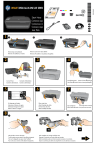
Figure 1. The LI-3000A front panel.
The area is computed as the length multiplied by the average width:
AREA = LEN × AV WD
The X value on the right of the display is the instantaneous value. This
value changes in real time as a sample is measured. The Y value is an
accumulator that you can use if you wish. X values can be added to the Y
value by pressing ADD. (Pressing the scanning head button twice in rapid
succession has the same effect as pressing the ADD key.) The SUB key
removes the last value entered from the Y register (useful if A D D is
mistakenly pressed). Note that this "last value" is not necessarily the
currently displayed X value, and that the last value cannot be removed more
than once.
3-2
Instrument Operation
AN EXAMPLE
1) Put a small piece of paper in the scanning head, pull the string out a
several centimeters, and let it back. The display will change to
something like
AREA
0
158.92
0.00
X
Y
27.4
0.00
X
Y
Sample length was 27.4 cm.
5.8
0.00
X
Y
Average sample widthwas 5.8 cm.
5.8
0.00
X
Y
Maximum sample widthwas 5.8 cm.
2) Press LEN.
LEN
0
3) Press AVE WIDTH.
AV WD
0
4) Press MAX WIDTH.
MX WD
0
5) Press AREA to return to the normal display. Now add the X value to
the Y value by pressing ADD. The display will change to
AREA
1
0.00
158.92
X
Y
3-3
Cleared after ADD.
1 value now in the accumulator.
Instrument Operation
Note that the X value clears after pressing A D D (this feature can be
disabled, and is discussed later), and that the sample counter on the bottom
left increments by one.
6) Pull the string again to measure another sample.
AREA
1
120.06
158.92
X
Y
The new sample.
7) Add the new X value to the Y value by pressing ADD.
AREA
2
0.00
278.98
X
Y
2 values in the accumulator.
8) Pull the string again to measure a third value.
AREA
2
21.46
278.98
X
Y
The third sample.
9) Subtract the last value added to the Y register by pressing SUB.
AREA
1
21.46
158.92
X
Y
The third sample is still displayed.
Note that 120.06 was subtracted.
Since the last value added was 120.06, that was what was removed from the
Y value. The X value remains unchanged. If you press SUB again, it will
have no effect, since the last entered value has already been removed.
3-4
Instrument Operation
SCANNING HEAD BUTTON
The white button on the LI-3000A scanning head has 2 uses. Pressing once
will clear the X register (same as pressing CLEAR X ). Pressing the
button twice in quick succession adds the X value to the Y value, just like
pressing ADD.
PULLING THE STRING TOO FAST
If you ever pull the string too fast, the message
PULLING TOO FAST
PRESS CLR X
X
Y
will be displayed. When CLEAR X is pressed, the X value will be cleared,
and normal operation will resume. Maximum string speed is about 1 meter
per second.
Making Measurements
When using the scanning head on attached leaves, observe the following 2
important principals:
• Pull the length encoding cord at the same rate the sample is being
pulled through the scanning head. This is accomplished by holding
the length encoding knob against a stationary object (stem, etc.) as
the scanning head is drawn over the sample.
• Pull the length encoding cord straight out from (perpendicular to)
the front plane of the scanning head (an angle of 11.5 degrees will
cause a 2% error).
AREA MEASUREMENT OF ATTACHED LEAVES
1) Move the ON-OFF switch to ON.
2) Open the scanning head and position it over a leaf. The leaf does not
have to be detached from the plant to be measured.
3-5
Instrument Operation
3) Close the scanning head over the petiole so that the leaf base is in the
scanning head but not between the LED and photodiode (detector)
windows. For plants such as corn, position the head as near to the leaf
base as possible.
4) Draw the length encoding cord to some location where it can be held
steady. The knob can be held against a stem (Figure 2), or in the case of
broadleaf plants, the knob can be held firm by clasping it together with
the petiole between the second and third fingers
5) Press the scanning head button once to clear the X register before
starting the measurement.
6) Draw the closed scanning head over the leaf while the length encoding
knob is held stationary. Drawing speed need not be constant.
7) After the scanning head has passed over the leaf, let the length encoding
cord slowly rewind itself back into the scanning head.
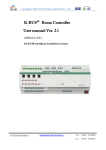
Figure 2. Operation Techniques.
Open the scanning head and
place it over the leaf. The
length encoding knob is held
against a stationary object
such as a stem.
3-6
Instrument Operation
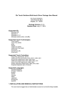
Close the scanning head at
the leaf base. Reset the instrument by pressing the scanning
head button once.
Draw the closed scanning head
over the leaf apex to pass
through completely. Drawing
speed need not be constant.
Figure 3. Soybean Measurement.
3-7
Instrument Operation
USING A TRANSPARENT SHEATH
A transparent sheath (user supplied) can be used to measure detached leaves
and other objects that require sample support (Figure 4). In order to gain
proficiency using a transparent sheath, measure several objects of known
area, such as graph paper cutouts.
If detached leaves are to be measured with a sheath, make the measurements
as soon as possible after harvesting with the samples kept moist to prevent
shrinkage or curling of the leaf margins.
Measurements with a transparent sheath can be accomplished using the
following steps:
1) Make sure the sheath is clean and then measure the empty sheath to be
certain that know spurious area is measured.
2) Place an object in the sheath about 6 cm from one end.
3) Open the scanning head and place the sheath in the head with about 4 cm
protruding from the left edge and allow the head to close.
Figure 4. Use of the Transparent Sheath
3-8
Instrument Operation
4) Grasp the length encoding knob with your left-hand thumb and
forefinger and hold it stationary against the sheath (Figure 4).
5) Press the scanning head button once to clear the X value on the display.
Draw the sheath through the scanning head, simultaneously drawing out
the length encoding cord.
HINTS FOR VARIOUS LEAF TYPES
Many types of leaves cannot be measured without additional support to
guide them through the scanning head. Techniques for several leaf types
are discussed below.
• Compound leaves can be measured by either scanning each leaflet, as
with the soybean trifoliate in Figure 3, or by enclosing the entire intact
leaf in a transparent sheath.
• Tender leaves such as those developed under low light conditions
sometimes will not easily slide through the scanning head and may
actually tear because of adherence to the instrument surfaces. In this case
a transparent sheath can be placed over the leaf for support and
protection.
• Insect damaged leaves which have protruding fragments or naturally
dissected leaves having fine lobes usually require support by a transparent
sheath.
• Small leaves such as those of alfalfa and small grasses can be removed
from the plants and placed in a transparent sheath.
• Elongated, narrow leaves (grasses, etc.) are most accurately measured if
they are passed through the scanning head at an angle to the line of LEDs
(instead of perpendicular).
In many cases the LI-3050A/4 Transparent Belt Conveyer Accessory
(Figure 5) will be the method of choice for measuring small objects and
detached leaves. The combination of the LI-3050A/4 and LI-3000A
provides greater accuracy ( ± 1%) than the LI-3000A alone ( ± 2%).
3-9
Instrument Operation
Storing Data In Memory
Readings can be stored in memory for later viewing or RS-232C output.
Stored readings can be any combination of the X register and the
accumulated readings in the Y register. When data is stored, it
automatically includes area, length, average width, and maximum width.
Stored data is in a file system. A file can be as large or as small as you wish.
A file must be opened before any data is stored. Closing the file precludes
adding any more data to that file. Associated with each file is some header
information: a number (assigned by the system), a label (entered by the
user), and the time and date the file was opened (as kept by the system).
When output, a file might look like this:
FILE: 1
REM:PLOT1
06 MAY 1990 14:22:30
ENTRY
COUNT
AREA
1
0
42.37
2
5
344.20
3
2
84.48
LENGTH
13.10
120.00
26.80
AV WIDTH
3.23
2.87
3.15
MX WIDTH
5.12
3.10
6.02
FILE: A sequential number assigned by the system that you use to
reference the file.
REM: A remark entered by the user when the file is first opened.
ENTRY: Sequential numbers identifying records in the file.
COUNT: The number of samples represented in the record. When X
values are stored, the count is always 0. Y values will always be an
integer greater than 0. The count represents the number of X values that
were added together before the accumulated Y value was stored in the
file.
For accumulated values, the AREA value is the total leaf area of all
samples, LENGTH is the total leaf length, AV WIDTH is the average width
of all samples, and MX WIDTH is the maximum width of all samples.
The following sequence of events could have occurred to make the above
file. It would be a good example to duplicate using your own console, as
well.
3-10
Instrument Operation
1) Press FILE to open a file. The display will show
FILE
1
OPENED
X
Y
Briefly displayed...
X
Y
ENTER REMARK:
__
2) The remark "PLOT1" is entered by pressing this sequence of keys:
P ↑ L ↑ O T ↑ SPACE 1 ENTER
To type the alpha characters in the lower left corners of the keys, just press
the desired key. To type the alpha characters in the upper left corners, press
↑ first, then the key. Typing mistakes can be corrected using the back arrow
key (←).
3) Now the display will show
AREA *
0
0.00
0.00
X
Y
42.37
0.00
X
Y
The * indicates that a file is open.
4) Measure a sample ....
AREA *
0
... and store it by pressing STORE X. The display will briefly show
FILE 1
ENTRY
1_
X
Y
followed by
3-11
Instrument Operation
AREA *
0
0.00
0.00
X
Y
Note the X value clears after pressing
STORE X.
5) Take 5 readings, following each by pressing ADD (or by pressing the
scanning head button twice).
AREA *
5
0.00
344.20
X
Y
5 samples in Y register (accumulator).
Now press STORE Y to store the Y register readings in the file.
X
Y
FILE 1
ENTRY
2_
AREA *
0
0.00
0.00
X
Y
Displayed briefly...
Note the Y value clears on STORE Y.
6) Take 2 more readings, following each by pressing ADD. Then press
STORE Y.
7) Close the file by pressing FILE.
FILE 1
CLOSED
X
Y
Displayed briefly...
The file is now similar to that shown at the beginning of this example.
STRUCTURING FILES
Since you have a lot of flexibility on exactly what values to store in a file, it
pays to exercise a little forethought on how to structure your files.
For example, suppose you wish to determine leaf area index in 10 different
plots by measuring leaf areas on 5 plants in each plot. One way to proceed
would be to use a file for each plot, so you'll have 10 files when done. Once
a file is opened, measure all leaves on the first plant, pressing ADD (or
3-12
Instrument Operation
press the white button on the scanning head twice) after each leaf. When
done with the plant, press STORE Y . Repeat for the other 4 plants on the
plot. When done with the plot, press FILE to close the file. At that point,
you will have 5 entries in the file, each one being the total leaf area of each
of the 5 plants sampled. The COUNT column on each line would tell you
how many leaves per plant were measured.
The file for one plot might look something like this:
FILE: 2
REM: TEST PLOT 2
08 MAY 1988 14:19:30
ENTRY
COUNT
AREA
1
7
246.68
2
5
125.20
3
4
84.48
4
9
344.20
5
5
140.69
LENGTH
45.10
35.60
26.80
120.00
47.32
AV WIDTH
3.23
2.87
3.15
4.67
3.56
MX WIDTH
5.12
3.10
6.02
6.10
5.72
Another approach would be to have one file per plant (giving you 50 files
when done). When measuring a plant, press STORE X and ADD after
each leaf measurement. After the last leaf on the plant is measured, press
STORE Y to store the accumulated leaf area for that plant and then close
the file. In order to know which plant goes with which plot, use the file
remarks to record that information. The file for one plant might look like
this:
FILE: 3
REM: PLOT 2 #5
09 MAY 1988 14:25:30
ENTRY
COUNT
AREA
1
0
42.37
2
0
44.20
3
0
24.48
4
0
29.50
5
0
34.86
6
0
19.33
7
6
194.74
LENGTH
13.10
12.90
9.78
10.20
11.50
8.60
66.08
AV WIDTH
3.23
2.87
3.15
2.83
2.32
2.14
2.76
MX WIDTH
5.12
3.10
3.67
2.98
2.76
2.56
5.12
Still another approach is to use one file for the entire data set. Begin each
plot with a cleared Y and X register, and press ADD after each leaf.
When done with a plot, press STORE Y. When done, your file will have
3-13
Instrument Operation
10 entries (one for each plot), and the COUNT for each entry will reflect the
total number of leaves measured.
Before you decide on how to structure your data files, you may also want to
consider the potential of loosing some of your data. If the console is
switched OFF, or if it automatically shuts itself off due to inactivity, the
current X and Y values will be lost. Any data which is stored in a data file
(the result of pressing STORE X or STORE Y) is safe, even if the data file
is not closed. The greatest potential for loss occurs when a large number of
measurements are added to the accumulator ( Y register) before they are
stored in a data file.
The configuration of the LI-3000A can be changed to facilitate rapid data
storage. This is accomplished using the CONFIG REGISTERS routine that
is discussed in the section titled Menu Key Routines.
VIEWING FILES ON THE DISPLAY
The VIEW key allows you to look at the contents of any stored file. When
the VIEW key is pressed, you will be prompted for the file number of the
file to be viewed:
X
Y
VIEW FILE
NUM:__
Enter the file number to be viewed.
If you enter a file number for which there is no file, the display will show
X
Y
FILE NOT FOUND_
and return to the normal display. Otherwise, you will be shown the header
of the selected file. For a typical file the display would show
FILE
1
REM: PLOT 1
(
3)
X
Y
File 1 has 3 entries.
Press the ↓ key to see the next part of the file header, which is the date and
time when the file was opened.
3-14
Instrument Operation
X
Y
06 JUN 1988
14:22:30
Press the ↓ key again to view the first of the 3 entries.
1/
AREA
3
0
42.37
X
Y
Entry 1 of 3 has 0 counts (e.g. it was
stored from the X register).
The top line displays the ENTRY number (1), the total entries (3), and the
COUNTS for that entry (0, indicating that it is an X value). The bottom
line displays AREA, LEN, AV WD, or MX WD depending upon which has
been selected using the AREA , LEN , AVE WIDTH , or MAX WIDTH
keys. Try pressing these keys before proceeding.
Pressing ↓ again will change to the second entry:
2/
AREA
3
5
344.20
X
Y
Entry 2 of 3 has 5 counts.
VIEW MODE KEY DEFINITIONS
While viewing a file, these keys will do the following things:
↑ and ↓ : Scroll up or down through a file.
VIEW: Will prompt for a new file to view.
DEL: Deletes the file that is currently displayed. When the DEL is
pressed, the user is prompted:
DELE
1? N
↑,↓, or ENTER
X
Y
To delete the file press the ↑ key to change the N to a Y, then press
ENTER. To continue without deleting the file, just press ENTER.
3-15
Instrument Operation
AREA , LEN , AVE WIDTH , or MAX WIDTH : Selects the data
column to be viewed.
All other keys will cause view mode to be exited.
DELETING A RANGE OF FILES
When DEL is pressed from normal operating mode (as opposed to the file
view mode), the user is prompted for a range of files to delete:
DELETE FILES
FROM:_
X
Y
FROM:10
THRU:_
X
Y
If 10 were entered for the starting
value. Enter the ending value.
Each file in the range that is deleted is shown on the display.
FILE
14
DELETED
X
Y
Counts through a range.
Or, resumes area display if not found.
If you wish to get out of the file delete routine, enter 0 (or press ENTER
without making an entry) for either the FROM or THRU file numbers. (See
also the discussion below on deleting all files.)
Menu Key Routines
The MENU key accesses a list of software routines.
MEMORY AVAILABLE
↑,↓, or ENTER
X
Y
3-16
Instrument Operation
Use the ↑ and ↓ keys to scroll through the list, and press ENTER to
perform any one. Press any other key to exit the menu list, and return to
normal operation. The list of routines is:
Memory Available
Set I/O
Print Files
Delete All Files
Config Registers
Set Clock
3100 Resolution
Shows % of memory available for storage.
Configures the RS-232C port (baud rate, data bits, etc.).
Outputs a user selected range of files to the RS-232C port.
Deletes all stored files.
Can set auto clear on ADD, STORE X, and STORE Y.
Sets time and date.
Sets high or low resolution if using the LI-3100 Area Meter.
To exit MENU list, press any key except ENTER , ↑ ,or ↓ .
MEMORY AVAILABLE
X
Y
100% REMAINING
PRESS KEY
Displays % of available memory.
Press any key to return to help menu.
The actual number of files or area entries that can be stored is highly
dependent on how the data is stored as indicated in the table below. When
the memory is full the message "NOT ENOUGH MEM" will be displayed
when you try to store data into a file.
Entries
Per File
1
2
3
4
5
10
15
20
.
.
2385
Total #
Entries
674
1052
1293
1460
1580
1900
2040
2100
.
.
2385
# Files
674
526
431
365
316
190
136
105
.
.
1
3-17
Instrument Operation
SET I/O
The SET I/O routine sequentially prompts for the following list of
parameters:
BAUD = 4800
↑,↓, or ENTER
X
Y
300, 1200, 2400, 4800, or 9600
DATA BITS = 8
↑,↓, or ENTER
X
Y
7 or 8
STOP BITS = 2
↑,↓, or ENTER
X
Y
1 or 2
PARITY = NONE
↑,↓, or ENTER
X
Y
EVEN, ODD, or NONE
DATA BITS = 8
↑,↓, or ENTER
X
Y
7 or 8
CHECK DTR = Y
↑,↓, or ENTER
X
Y
Y or N (Pin 20 high?)
XON/XOFF = N
↑,↓, or ENTER
X
Y
Y or N
CHECK RTS = N
↑,↓, or ENTER
X
Y
Y or N (Pin 4 high?)
CHECK DTR=Y Hardware pacing: DTR line. When set to 'Y' the
LI-3000A will send data only when it sees pin 20 (DTR) of the I/O port
3-18
Instrument Operation
high (> 3V). This method of pacing is commonly used in printers (as is the
case with the 6000-03B Printer from LI-COR).
XON/XOFF=N XON/XOFF software handshake. The LI-3000A will
transmit data until an XOFF character (hex 13, ASCII DC3) is received.
Data transmission will resume upon receipt of an XON character (hex 11,
ASCII DC1). This is a fairly common handshaking protocol.
CHECK RTS=N Hardware handshake. When CHECK RTS is set to "Y",
the LI-3000A will only send data when it sees pin 4 (RTS) of the I/O port
high (> 3V). The 6000-03B Printer does not support this handshaking
protocol (set CHECK RTS to 'N').
More information on transferring data to a computer or printer can be found
in the Data Communications section.
PRINT FILES
This routine prompts the user for a range of files to be transmitted out the
RS-232C port. Entering a 0 or just pressing ENTER in response to either
the FROM or THRU prompts will abort this routine.
PRINT FILES
FROM_
X
Y
FROM: 10
THRU:_
X
Y
If 10 were entered for
the starting value
DELETE ALL FILES
DELETE FILES = N
↑,↓, or ENTER
X
Y
Pressing ↑ (to change the N to a Y) followed by ENTER will clear all files
from memory.
3-19
Instrument Operation
CONFIG REGISTERS
The user can choose whether the X value is automatically cleared when the
ADD key is pressed (or the white button double pressed), when the
STORE X key is pressed, or whether the Y value is automatically cleared
when the STORE Y key is pressed.
CLR X ON ADD? Y
↑,↓, or ENTER
X
Y
CLR X ON STORE? Y
↑,↓, or ENTER
X
Y
CLR Y ON STORE? Y
↑,↓, or ENTER
X
Y
These prompts are used to facilitate rapid data collection and storage. For
example, if you wish to store only accumulated measurements of all leaves
on a plant, set "CLR X ON ADD" to Y so that the X value is cleared after
the area of each leaf is added to the Y value. This eliminates having to
press the white scanning head button or the CLEAR X key in-between
each leaf measurement.
Now assume that you wish to store the leaf area of each individual leaf and
the total leaf area of the whole plant. Two operations need to occur after
each leaf is measured; the individual leaf area data should be stored using
the STORE X key and the individual leaf area data should be added to the
Y value to collect the whole plant leaf area. To accomplish this, set the
"CLR X ON STORE" prompt to No and the "CLR X ON ADD" prompt to
Yes. This assumes that you will press STORE X before ADD. If you
wish to press ADD before STORE X set "CLR X ON ADD" to No and
"CLR X ON STORE" to Yes.
Normally it is advantageous to have the "CLR Y ON STORE" prompt set to
Yes. However, you may find a need to store an accumulated value (such as
whole plant leaf area) and continue to add new measurements afterward.
3-20
Instrument Operation
SET CLOCK
DATE=20 JUN 1988
NEW=DD MMM YYYY
X
Y
TIME=14:32:10
NEW=HH:MM:SS
X
Y
Pressing ENTER without making any entries will leave the data or time
unchanged. To enter a new date or time, type in the appropriate characters
to match the indicated NEW= format.
Valid entries for the months January through December are JAN, FEB,
MAR, APR, MAY, JUN, JUL, AUG, SEP, OCT, NOV, and DEC
respectively.
LI-3100 RESOLUTION
This allows the user to tell the LI-3000A which resolution is being used on
the LI-3100. It has no effect on measurements with the LI-3000A scanning
head.
3100 RES = LOW
↑,↓, or ENTER
X
Y
LOW or HI.
"LOW" is for 1.0 mm resolution and "HI" is for 0.1 mm resolution on the
LI-3100.
Data Communications
Although each data file can be viewed on the display, an RS-232C interface
has been provided to transfer data to a printer or computer for analysis or
storage.
3-21
Instrument Operation
GENERAL INFORMATION
The RS-232C port is configured as Data Communication Equipment (DCE),
so it transmits data on pin 3, and receives data on pin 2. When connecting
to a device that is configured as Data Terminal Equipment (DTE), such as
most serial printers and desktop computers, a straight-thru cable is all that is
needed (included in the LI-3000A standard spare parts kit). To
communicate successfully with another DCE device, a cable exchanging
pins 2 and 3 (and perhaps 6 and 20 as well) would be needed.
The communication parameters (baud rate, parity, etc.) of the LI-3000A can
be set to match the receiving device using the SET I/O routine in the Menu
Key functions. The LI-3000A can handshake in any combination of three
ways: it can look at pin 20 (DTR), pin 4 (RTS), and it supports XON/XOFF.
SENDING DATA TO AN IBM PERSONAL COMPUTER
In order to transfer data to an IBM PC (or compatible), two things are
needed: the proper cable(s) and software that writes the incoming data into a
data file.
The LI-3000A is connected to a serial port on the standard IBM PC using
the provided interface cable and the female to female gender changer. If
you are using an IBM AT or an AT compatible, you may need a 25-pin to 9pin conversion cable which you should be able to find at a local computer
store.
For data transfer software, any program which can write incoming ASCII
data into a data file will suffice. Most commercially available
communication packages perform this type of data transfer. Several
inexpensive programs and their manufacturers are listed below.
Program Name: ProComm
Datastorm Technologies, inc.
P.O. Box 1471
Columbia, MO 65205
Program Name: PC-Talk
Freeware
P.O. Box 862
Tiburon, CA 94920
3-22
Instrument Operation
TRANSFERRING DATA TO THE APPLE®, MACINTOSH™
Connecting the LI-3000A to the Macintosh requires the provided interface
cable, the female to female gender changer and a Hayes compatible modem
cable for the Macintosh.
For data transfer software, a number of programs are commercially
available. One such program is Red Ryder which is available from the
Freesoft Company at a nominal cost. Their address is given below.
Program Name: Red Ryder
The Freesoft Company
150 Hickory Drive
Beaver Falls, PA 15010
PRINTING DATA ON THE 6000-03B PRINTER
The 6000-03B serial port configuration is determined by two banks of DIP
switches located on the serial interface board. They are set at LI-COR for 2
stop bits, parity odd and disabled, flag positive, and 4800 baud. The dip
switches should be set as shown below.
1
6
1
8
ON
OFF
SW1
SW2
To configure the printer for a different baud rate, consult the EPSON Serial
Interface Manual for complete information on the dip switches.
The LI-3000A can be connected directly to the 6000-03B using the
provided interface cable.
3-23
Instrument Operation
The LI-3000A communication parameters are set using the SET I/O routine
on the MENU key. For the 6000-03B, they should be set as follows:
BAUD = 4800
DATA BITS = 8
STOP BITS = 2
PARITY = NONE
CHECK DTR = Y
XON/XOFF = N
CHECK RTS = N
Files are printed using the PRINT FILES routine which is accessed by
pressing the MENU key and scrolling to the desired software routine.
SOLVING COMMUNICATION PROBLEMS
Below are a few of the common communication problems and a few things
to check in order to facilitate solving the problem.
PROBLEM
WHAT TO CHECK
Nothing Happens
Proper Cable? Connections tight?
Printer on-line?
Check baud rate.
Check data bits, stop bits, or parity.
All characters are wrong
Some characters are wrong
3-24
Section IV
Operation with the LI-3100 Area Meter
The LI-3000A console can be connected to the LI-3100 Area Meter using
the following procedure.
1) Turn both instruments off.
2) Connect the 3000A-03 Interface Cable (9 pin connectors on each end) to
the LI-3100 and to the LI-3000A as shown in Figure 5 below. The
LI-3000A console can be connected directly to LI-3100's with serial
numbers LAM653 and above. For units with serial numbers LAM652
and below, the 3000A-04 Interface Kit is available (includes the 3000A03 Interface Cable). NOTE: The 3000A-04 Interface Kit requires an
electronics technician for installation, or it can be installed at LI-COR by
returning your instrument.
3) Disconnect the LI-3000A scanning head.
Figure 5. LI-3000A console connected to the LI-3100.
4-1
Operation with the LI-3100
4) Turn both instruments on.
IMPORTANT: The LI-3000A console "senses" during power on
whether the scanning head or the LI-3100 is connected. It is important
that the interface cable be connected to both instruments before the LI3000A is powered on.
5) After the start-up messages (see Basic Operation, Section III) you should
set the LI-3100 resolution as explained at the end of Section III.
The LI-3000A console will now collect and display data as described in the
Section III, with the exception that the reset switch on the LI-3100 now has
the same effect as pressing the CLEAR X key.
NOTE: The LI-3100 output signal is a digital signal which is in a form
that can be interpreted by the 3000A-01 Console. The digital output is not
an RS-232C output and should not be connected to an RS-232C device.
4-2
Section V
Maintenance and Calibration
Cleaning the LED and Photodiode
Windows
As debris collects on the scanning head windows (insects, dirt, pollen, etc.),
spurious numbers will accumulate on the display when the length encoding
cord is drawn. This is detected by moving the cord when no sample object
is located in the scanning head. Clean the quartz windows with a moist
paper towel or cloth. Wiping the windows with a finger is usually adequate
for field use.
Cleaning the Length Encoding Cord
Guide
A dust trap is located within the length encoding cord guide (the plastic
grommet through which the cord passes). This trap reduces dust passage
into the scanning head as the cord is retracted. The cord guide should be
unscrewed from the upper scanning head section and the felt trap cleaned or
replaced. The service frequency should be determined by experience under
the most prevalent usage conditions. The interval will range from seldom
under laboratory conditions, to daily in dusty or heavily pollinating crops.
Length Encoding Cord
If the length encoding cord becomes lodged, the problem is likely backlash.
This seldom occurs even if the cord is released and allowed to retract
rapidly. If the operator tends to "push" the cord into the head more rapidly
than the system will retract, then a slack cord occurs and backlash is more
probable. This is corrected by loosening the cord guide and removing the
seven screws on top of the scanning head. The upper section housing is
then raised straight upward. The cord is rewound and threaded according to
Figure 6. When the upper section housing is replaced, do not use force.
5-1
Maintenance and Calibration
Figure 6. The length encoding cord passes from the take-up reel
around the encoding wheel.
Warning: When replacing the upper section housing do not allow contact
with the protruding edge of the LED scanner. High temperature vacuum
grease is used as a seal between the upper section housing and the base
plate. The grease is forced into the joint after the cover is attached.
Knob Separation from the Length
Encoding Cord
The length encoding cord will retract completely into the scanning head if
the knob is removed. The cord is retrieved by opening the upper housing.
Avoid continuous application of sharp angles at either end of the scanning
head cord.
Battery Replacement
As the internal battery ages, the battery life will diminish (15 hours is
normal). Eventually the battery will fail to hold a charge and should be
replaced. If the battery is faithfully recharged when depleted, it should last
a number of years. It is not recommended that a replacement battery (model
5-2
Maintenance and Calibration
number 3000A-05) be ordered until the battery life of the first battery starts
to change noticeably. If a replacement battery is ordered it should be
installed immediately to prevent it from deteriorating in storage.
To perform the change, you will need the 3/16" nut driver included with the
instrument, a standard screwdriver, and a long nose pliers. Take the
following steps.
1) Unplug the AC power cord and use an anti-static work station while
changing the battery.
2) Remove the 4 screws on the edges of the cover and carefully lift it off.
Disconnect the keypad cable from the circuit board.
3) Remove the 4 hex screws from the 25 pin RS-232C connector and the 9
pin LI-3100 connector.
4) Remove the 4 outermost screws on the bottom (outside) of the box.
5) Slide out the circuit board assembly.
6) Unplug the battery and quickly plug in a new one.
CAUTION: If the battery is unplugged for more than 20 seconds, the
data, date, time, and calibration may be lost.
7) Unplug the other connections on the circuit board assembly and
separate it from the box.
8) Remove the 2 battery bracket screws from the bottom (outside) of the
box.
9) Install the battery bracket on the new battery.
10) Reassemble by performing the above steps in the reverse order.
Internal Fuse
If nothing happens when the LI-3000A is turned on, turn the instrument off,
plug in the AC power cord and turn it on again. If the LI-3000A is still
unresponsive, check the AC fuse (AGC 0.5 amp, fast blow type) on the
outside of the instrument. If replacing the AC fuse still does not cause the
instrument to function properly, check the fuse inside the instrument. The
interior fuse (AGC 2 amp, fast blow type) is mounted on the lower circuit
board as shown in Figure 7. Use steps 1 through 5 under battery
replacement to disassemble the case.
5-3
Maintenance and Calibration
Figure 7. Location of the internal fuse.
Instrument Storage
The internal battery should always be fully charged before storage. For
long term storage the battery should be recharged every 3 months to prevent
memory loss.
The LI-3000A should be stored in an area that is within the temperature
range -20 to 55 #C and has a relative humidity of 0 to 90%.
Test Menu
The TEST key accesses a list of technician test and calibration routines.
TEST: keyboard
↑,↓, or ENTER
X
Y
These routines are generally used during the technician check-out of the
LI-3000A. The list does, however, contain the calibration routine used to
calibrate a scanning head to the LI-3000A console.
5-4
Maintenance and Calibration
Test:keyboard
Test:DISPLAY
Test:prom
Test:ram
Test:clock freq
Test:clock
Test:RS-232 out
Test:RS-232 inout
Test:lobatt
Test:speedup
Test:thresh comp
Master Reset
Cal Pause
Calibrate
View Cal
Cal Edit
Print Cal
Shows grid location of each pressed key.
Cycles through the character set.
Tests the EPROM.
Shows memory size, and does a checksum test.
Used to measure the accuracy of the real time clock.
Displays date and time continually.
Tests the output of the UART.
Tests the input and output of the UART.
Displays low battery symbol if battery is low.
Allows checking of U3 on the analog board.
Allows checking of the comparator (U11) threshold.
Clears all data, time, date, calibration.
Slows down calibration routine for troubleshooting.
Sensor head calibration routine.
View the calibration.
Used to change the calibration data.
Output the calibration to the RS-232C port.
To exit the TEST menu press any key except ENTER , ↑ , or ↓.
TEST: KEYBOARD
The message 'keytest' is momentarily displayed, then the display will be
blank. When you press a key, the display will show the row number and the
column number of the pressed key. The ↑ key is 0,0 and the STORE Y
key is 3,5.
2
4
X
Y
3rd row down, 4th from the right.
This is the "6" (or V) key.
To exit this mode, press any key three times, or press all of the keys.
TEST: DISPLAY
The console will cycle through the display's character set. If you want to
quit before it finishes, press any key.
#####################
#####################
X
Y
5-5
Note that the first symbol displayed is
the low battery symbol (Lo).
Maintenance and Calibration
TEST: PROM
This routine does a checksum test on the EPROM.
PROM OK
X
Y
PROM passed the test.
Press any key to return to the menu.
TEST:RAM
This routine shows the size of the memory, and gives it a test.
32K RAM
OK
X
Y
Press any key to return to the menu.
5-6
32K bytes memory.
Displayed after a few seconds.
Maintenance and Calibration
TEST: CLOCK FREQ
This test is used to check the accuracy of the real time clock.
ADJUST FREQUENCY
PRESS KEY
X
Y
The frequency on Pin 1 of component U24 (6242) should be 64.00000 hertz
as measured by a frequency counter. Any error from 64 Hz is directly
proportional to the error that will be seen in time.
Freq. Measured
64.01000
64.00100
64.00010
64.00001
Error
+ 7 min/month
+ 40 sec/month
+ 4 sec/month
+ .4 sec/month
As a part of the clock frequency test, the real-time clock is set to zero. At
the end of the test the user is prompted to enter the current date and time.
TEST: CLOCK
20 JUN 1988
15:27:33
X
Y
Displays current date and time.
Press any key to return to the menu.
TEST: RS-232 OUT
This test transmits the character set out the RS-232C port. A printer must
be connected. Press the ← key to abort the test if problems occur.
5-7
Maintenance and Calibration
TEST: RS-232 INOUT
This test sends a space (ASCII decimal 32) and expects or receive a space (a
loopback connector must be installed). The data sent should match the data
received.
Press ENTER to start the test. Any of the following results may occur
TEST:RS232 inout
↑,↓, or ENTER
X
Y
Test passed. The data received
matched the data transmitted.
RECEIVER ERR
X
Y
No data was received. (A loopback
connector was not used).
RECEIVE DATA ERR
X
Y
Data received did not match
transmitted data.
The "receive data err" message can occur if an EPSON RX-80 printer is
connected. The RX-80 continually sends XOFF characters.
TEST:LOBATT
The low battery symbol will appear if the battery is low.
Lo
LOWBATT TEST
X
Y
Press any key to return to the menu.
5-8
Maintenance and Calibration
TEST:SPEEDUP
S
SPEEDUP TEST
X
Y
S (slow) or F(fast).
Tests component U3 on the analog board. When the string is being pulled
faster than 1/2 meter/second, then an F (fast) should appear. When the
instrument is in fast mode it no longer tries to update the display. Instead, it
concentrates only on counting area. The data is still 100% reliable and the
newest data will be displayed once the string speed slows down.
TEST: THRESH COMP
This test sets the comparator threshold voltage so it can be measured.
THRESH COMP = CAL
↑,↓, or ENTER
X
Y
TP30 = voltage set by calibration
potentiometer on analog board (≈0.5V).
THRESH COMP = 0.7V
X
Y
TP30 = 0.7V.
THRESH COMP = 0.9V
X
Y
TP30 = 0.9V.
THRESH COMP = 1.0V
X
Y
TP30 = 1.0V.
5-9
Maintenance and Calibration
MASTER RESET
Clears all data, the time, date, and scanning head calibrations. This test is
equivalent to unplugging the battery. It should be used if a new software
program (EPROM U4, digital board) is installed.
CAL PAUSE
Used to slow down the calibration routine for troubleshooting.
Cal Pause
↑,↓, or ENTER
X
Y
Press ENTER to start the routine.
Cal Pause = N
↑,↓, or ENTER
X
Y
This will pause the calibration after all
LED values are determined.
Press ↑ and then ENTER to set the pause prompt to Yes (Y).
Cal Pause = Y
↑,↓, or ENTER
X
Y
This will pause the calibration after each
LED value isdetermined.
Press ENTER to exit the routine.
CALIBRATE
The calibration routine must be done if a different scanning head is to be
used with the LI-3000A. Read the warning under the INSTRUMENT
CALIBRATION heading in Section I of this manual.
Before proceeding with this test, make sure the scanning head is cleaned,
and that nothing is blocking any of the LEDs.
5-10
Maintenance and Calibration
ENTER HEAD SR NO
X
Y
Enter the sensor head serial number.
The serial number entered at this prompt is used in the start-up message
("Calibrated for Head #xxxx") given when the LI-3000A is turned on.
ENTER REMARK
X
Y
PRECAL
LED# 15
X
Y
Shows the LED that is currently being
calibrated (0 to 127, #15 shown.
The PRECAL procedure is a first pass to approximately adjust the LED
values.
CAL
LED#
15
X
Y
The current of each LED is increased until its brightness provides a 1.0 volt
signal. Each LED is calibrated 4 times and then averaged.
At this point an error message will be displayed if a problem occurred
during calibration. Error messages are discussed below.
CAL DONE
PRESS KEY
X
Y
The calibration was successful and it
passed its performance check.
Error Messages
If an error message occurs, power the LI-3000A off, then back on. Recheck the scanning head to be sure it is cleaned and free of any debris.
Then do the calibration routine again. If the error message persists,
contact LI-COR.
There are three error messages as listed below.
5-11
Maintenance and Calibration
2 LEDS FAILED
PRECAL: CONT? N
X
Y
2 LEDS FAILED
CALIBRATION
X
Y
WARNING: NOISY
OR LOW LEDS
X
Y
Some of the LEDs dipped below 0.7 volts
during the performance check.
NOTE: The following information applies to calibrations for scanning
heads with serial numbers 196 or below.
Read the note in the calibration discussion in Section I.
These heads require a specially configured console (a jumper is changed)
and cannot automatically be calibrated by the console. Instead, their
original calibration must be used. With instruments having serial numbers
196 and below, calibration is controlled by the head. With instruments
having serial numbers 197 and above, calibration is controlled by the
console.
Do a calibration using the special LI-3000A console. The LED values will
all be 2's. The console will think it has just calibrated the head, but in
reality the original head calibration is used.
VIEW CAL
LI-3000A
CALIBRATION
X
Y
1: 55
2L 41
X
Y
37
29
5-12
Use ↑ and ↓ to scroll through the file.
Maintenance and Calibration
The first LED is using a current level corresponding to 55 (approximately
55 mA). The possible range is 0 to 255. "37" is the base 16 equivalent to
55.
The ↑ and ↓ keys will scroll through the 128 calibration values. Press any
key to return to the menu.
EDIT CAL
The Edit Cal routine allows the scanning head calibration data to be
changed. Normally the calibration should never need to be manually
changed. This routine may be of use in special cases if the head fails the
autocalibration routine and the user wants to temporarily get the instrument
working. If the instrument fails the autocalibration routine, then it does have
a problem and should be returned to LI-COR for repair.
The only time it is desirable to change the calibration data is when the
scanning head has a weak LED that cannot be lit to the same intensity as the
other LEDs. The autocalibration routine will completely turn that LED off
(its calibration value will be 0). Thus 1 mm2 of area will always be
counted for each millimeter of string travel for each LED that is off. By
editing that LED to some nonzero value from 1 to 255, the LED may be
made bright enough so that it no longer causes counts to appear when the
string is pulled with an empty head. A typical value for the edited number
may be about 100 (0 is off, 255 is brightest).
The accuracy of the instrument will generally be degraded after the
calibration file is edited. This is especially true if the edge of the leaf is near
the edited LED. (See to the Theory of Operation. The leaf/no leaf decision
will no longer be at 50% for that LED).
The access code to get into this routine is FP5. This code is the same for all
LI-3000As. Once a number is edited, an "e" will appear next to that number
in the table. The edited calibration data can only be used until the
instrument is turned off. A "CAL FILE LOST" message is displayed if the
5-13
Maintenance and Calibration
instrument is turned off and back on, and the autocalibration routine must be
used to recalibrate the head.
PRINT CAL
The calibration file is printed (via the RS-232C port) using this function.
PRINTING
X
Y
A sample calibration table is shown on the following page.
On the 5th line of the header (noise at 0.9V is 0/12800 cnts), the 0 indicates
that none of the LEDs dipped to 0.9V (1.0V is optimum). A non-zero
number indicates that the head may have a few weak leads. On the 6th line
if this number is non-zero, then the calibration either failed or probably
would fail if run again.
If you encounter communication problems during printing, press the ← key
to abort the routine.
5-14
Maintenance and Calibration
LI-3000A Calibration (Sample)
HEAD SR #1611
REMARK: XXX XXX XXX
3 MAY 1988 15:42:39
NOISE AT 0.9V IS
0/12800 CNTS
NOISE AT 0.7V IS
0/12800 CNTS
CAL MAX VAL: 80
CAL MIN VAL: 42
LED
DEC
HEX
LED
DEC
HEX
LED
DEC
HEX
LED
1:
70
46
33:
2:
49
31
34:
46
2E
65:
54
36
66:
3:
49
31
35:
52
34
4:
43
2B
36:
51
5:
48
30
37:
6:
47
2F
7:
48
8:
47
2F
97:
64
40
52
34
98:
68
44
67:
47
2F
99:
52
34
33
68:
46
2E
100:
54
36
55
37
69:
47
2F
101:
60
3C
38:
47
2F
70:
46
2E
102:
56
38
30
39:
44
2C
71:
48
30
103:
60
3C
48
30
40:
48
30
72:
52
34
104:
64
40
9:
57
39
41:
54
36
73:
47
2F
105:
58
3A
10:
49
31
42:
53
35
74:
62
3E
106:
66
42
11:
47
2F
43:
45
2D
75:
58
3A
107:
49
31
12:
42
2A
44:
44
2C
76:
59
3B
108:
46
2E
13:
46
2E
45:
50
32
77:
66
42
109:
47
2F
14:
42
2A
46:
48
30
78:
54
36
110:
72
48
15:
43
2B
47:
48
30
79:
52
34
111:
53
35
16:
51
33
48:
56
38
80:
64
40
112:
72
48
17:
47
2F
49:
54
36
81:
57
39
113:
52
34
18:
46
2E
50:
58
3A
82:
67
43
114:
52
34
19:
45
2D
51:
46
2E
83:
50
32
115:
52
34
20:
47
2F
52:
48
30
84:
49
31
116:
54
36
21:
60
3C
53:
52
34
85:
60
3C
117:
58
3A
22:
52
34
54:
43
2B
86:
48
30
118:
53
35
23:
44
2C
55:
50
32
87:
46
2E
119:
50
32
24:
58
3A
56:
48
30
88:
57
39
120:
46
2E
25:
49
31
57:
46
2E
89:
48
30
121:
48
30
26:
46
2E
58:
50
32
90:
56
38
122:
48
30
27:
54
36
59:
49
31
91:
48
30
123:
62
3E
28:
44
2C
60:
48
30
92:
54
36
124:
46
2E
29:
45
2D
61:
46
2E
93:
52
34
125:
46
2E
30:
50
32
62:
52
34
94:
62
3E
126:
80
50
31:
50
32
63:
58
3A
95:
54
36
127:
82
34
32:
56
38
64:
48
30
96:
58
3A
128:
67
43
5-15
DEC
HEX
Section VI
LI-3050A Transparent
Belt Conveyer Accessory
Setup and Adjustment
Loosen the knurled knobs (1a, Figure 8) on both sides of the upper pulley
assembly. Leave the upper pulley in the down position and slide a
transparent belt onto the assembly from the front. Lift the knurled knobs
and tighten them when the desired belt tension is obtained.
Support the weighted lower most pulley (1b, Figure 8) with a piece of foam
rubber to hold it in a maximum upward position. Slide a transparent belt
onto the lower pulley assembly from the front. Remove the foam support
and center the belt while lifting the lower pulley manually. When the belt is
centered, release the lower pulley. The weight automatically provides
adequate tension. Mounting the lower belt can be simplified by placing a
sheet of paper under the lower surface of the upper belt to prevent cohesion
as the lower belt is put into place.
IMPORTANT: Place the belts so that the edges and seems of one are
slightly misaligned with the other. When the edges are aligned, background
counts can occur.
Turn the knurled knob on the front of the lower pulley assembly (1c, Figure
8) counterclockwise to lower the scanning head support blocks. Open the
scanning head and slide it into the LI-3050A (Figure 9). When the scanning
head is inserted so that about 1/8" is protruding from the front of the LI3050A, raise the scanning head support blocks by turning the knurled knob
(1c, Figure 8) clockwise against the right hand stop.
Do not lower the scanning head support blocks while the belts are moving.
Only lower scanning head support blocks when the scanning head is about
to be removed.
6-1
LI-3050A/4 Belt Conveyor
Figure 8. Transparent Belt Conveyer Accessory
Figure 9 . Scanning Head Installation.
6-2
LI-3050A/4 Belt Conveyor
Connect the LI-3050A cord into LI-3050A connector on the side panel of
the LI-3000A. The LI-3000A must be turned off or unplugged during
this step. Check the 115/230 voltage selection switch before turning on the
LI-3000A.
The LI-3050A is turned on and off by the power switch on the LI-3000A.
There is not a separate power switch on the LI-3050A. Plug the LI-3000A
into the proper AC source and turn on the instrument.
Reset the system by pressing the white button (1d, Figure 8) located above
the LI-3050A sample hopper. Pressing the reset button has the same effect
as pressing CLEAR X on the keypad.
Allow the 10 cm2 (or 50 cm2 ) calibration disk to pass through the scanning
head. Either catch the disk as it passes out of the system or place a pad on
the instrument case. Failure to do this will eventually cause damage to the
finish.
The calibration accuracy is adjusted by turning the "CAL ADJ"
potentiometer on the console using a small screwdriver (see LI-3000A
Theory of Operation). The resulting reading should be very near 10 cm2 .
The purpose of the "CAL ADJ" potentiometer is not to calibrate out
spurious counts on a belt system, but rather to provide 1% accuracy on a
clean belt. If the belt is dirty (resulting in spurious counts), it is preferable
to clean the belt rather than to turn the "CAL ADJ" potentiometer.
If the belts do not track acceptably, loosen the hex screws (1e, Figure 8) on
the front of the instrument and twist the upper pulley assembly. To produce
inward belt travel, apply clockwise pressure to the upper pulley assembly
(1f, Figure 8). The opposite procedure is used for the lower pulley
assembly. Do not remove the screw. Loosen them only enough so that they
remain finger tight. Probably no detectable movement will result as the
rotation pressure is applied to the pulley assembly. Tighten the screw and
observe the belt track. Adjust more as necessary.
Storage and Maintenance
When the LI-3050A is not in operation, place a block under one edge of the
lower idler to remove tension from the lower belt. Release tension from the
upper belt also. This prevents excessive belt stretching.
If the storage area is not very clean it is best to remove the belts prior to idle
periods of more than a few days. Wrap the belts in paper (paper towels) in a
manner that prevents cohesion.
6-3
LI-3050A/4 Belt Conveyor
The transparent belts can be cleaned with warm water and hand dishwashing detergent.
Do not lubricate the drive gears. This will interfere with the optical switch
(part #141) which encodes the sample length.
6-4
Appendix A
LI-3000A Specifications
Resolution: 1 mm2 (1 mm x 1 mm scanning area).
Accuracy: Within ± 2% for samples > 50 cm2 .
Display Capacity: Area: 9,999,999.99 cm2 , Length: 99,999,999.9 cm, Width:
12.8 cm
Display: 2 line x 16 character LCD
Keyboard: Sealed, 24 key tactile response.
Real Time Clock: Year, month, day, hour, minute, second.
Accuracy: ± 3 minutes per month (25 °C).
Internal Memory: 32K bytes RAM.
Memory Capacity: From 675 entries (675 files, 1 entry each) to 2385 entries
(1 file, 2385 entries).
Communications: RS-232C hardwired Data Communications Equipment
(DCE). Baud rates are selectable at 300, 1200, 2400, 4800, 9600.
Sample Dimensions
Width: 127 mm maximum, 1 mm minimum.
Thickness: 8 mm maximum.
Length: 1 meter maximum.
Scanning Speed: Length encoding cord drawing speed need not be constant.
Error message indicates if encoding cord is drawn too fast (> 1 meter s-1).
Power Requirement: Rechargeable 6 V lead-acid battery; or 108-126/216252 VAC, 48 to 66 Hz, 25 watt maximum.
Battery Capacity: 15 hours of continuous operation.
Recharging Time: 5-8 hours, instrument off. Charging circuitry built-in.
Battery Voltage Sensor: Automatically shuts instrument off when low battery
condition exists. Also provides a low battery warning approximately 1 hour
before shutdown. The remaining power maintains data stored in memory.
Operating Temperature: 0 to 55 °C, 0 to 80% RH (noncondensing).
Storage Temperature: -20 to 55 °C, 0 to 80% RH (noncondensing).
Scanning Head
LED Light Source: 6.4 mm from outer edge.
Size: 30.5 cm overall length (12.0 ").
Weight 680 g (1.5 lb.).
Readout-Control Unit
Size: 19.8 L x 15.5 W x 10.1 cm D (7.8" x 6.1" x 4.0").
Weight: 2.0 kg (4.4 lb).
A-1
Appendix B
LI-3050A Specifications
Resolution: 1 mm2 (1 mm x 1 mm scanning area).
Accuracy: Within ± 1% for samples > 10 cm2 .
Sample Dimensions
Width: 127 mm maximum, 1 mm minimum.
Thickness: 7.5 mm maximum.
Length: unlimited.
Conveyer Belt Speed: 6.3 cm s-1 at 60 Hz; 5.4 cm s-1 at 50 Hz.
Transparent Belts: Rugged clear vinyl.
Power Requirement: 108-126/216-252 VAC, 48 to 66 Hz.
Operating Temperature: 0 to 55 °C.
Storage Temperature: -20 to 65 °C.
Size: 27.9 H x 27.9 W x 38.1 cm L (11.0" x 11.0" x 15.0")
Weight: 7.7 kg (17.0 lb).
A-2
Warranty
Each LI-COR, inc. instrument is warranted by LI-COR, inc. to be free from
defects in material and workmanship; however, LI-COR, inc.'s sole
obligation under this warranty shall be to repair or replace any part of the
instrument which LI-COR, inc.'s examination discloses to have been
defective in material or workmanship without charge and only under the
following conditions, which are:
1. The defects are called to the attention of LI-COR, inc. in Lincoln,
Nebraska, in writing within one year after the shipping date of the
instrument.
2. The instrument has not been maintained, repaired or altered by anyone
who was not approved by LI-COR, inc.
3. The instrument was used in the normal, proper and ordinary manner and
has not been abused, altered, misused, neglected, involved in an accident or
damaged by act of God or other casualty.
4. The purchaser, whether it is a DISTRIBUTOR or direct customer of
LI-COR or a DISTRIBUTOR'S customer, packs and ships or delivers the
instrument to LI-COR, inc. at LI-COR inc.'s factory in Lincoln, Nebraska,
U.S.A. within 30 days after LI-COR, inc. has received written notice of the
defect. Unless other arrangements have been made in writing,
transportation to LI-COR, inc. (by air unless otherwise authorized by
LI-COR, inc.) is at customer expense.
5. No-charge repair parts may be sent at LI-COR, inc.'s sole discretion to
the purchaser for installation by purchaser.
6. LI-COR, inc.'s liability is limited to repair or replace any part of the
instrument without charge if LI-COR, inc.'s examination disclosed that part
to have been defective in material or workmanship.
There are no warranties, express or implied, including but not limited
to any implied warranty of merchantability of fitness for a particular
purpose on underwater cables or on expendables such as batteries
and lamps .
Other than the obligation of LI-COR, inc. expressly set forth herein,
LI-COR, inc. disclaims all warranties of merchantability or fitness for a
particular purpose. The foregoing constitutes LI-COR, inc.'s sole
obligation and liability with respect to damages resulting from the use
or performance of the instrument and in no event shall LI-COR, inc. or
its representatives be liable for damages beyond the price paid for the
instrument, or for direct, incidental or consequential damages.
The laws of some locations may not allow the exclusion or limitation on
implied warranties or on incidental or consequential damages, so the
limitations herein may not apply directly. This warranty gives you specific
legal rights, and you may already have other rights which vary from state to
state. All warranties that apply, whether included by this contract or by law,
are limited to the time period of this warranty which is a twelve-month
period commencing from the date the instrument is shipped to a user who is
a customer or eighteen months from the date of shipment to LI-COR, inc.'s
authorized distributor, whichever is earlier.
This warranty supersedes all warranties for products purchased prior to June
1, 1984, unless this warranty is later superseded.
DISTRIBUTOR or the DISTRIBUTOR's customers may ship the
instruments directly to LI-COR if they are unable to repair the instrument
themselves even though the DISTRIBUTOR has been approved for making
such repairs and has agreed with the customer to make such repairs as
covered by this limited warranty.
Further information concerning this warranty may be obtained by writing or
telephoning Warranty manager at LI-COR, inc.
IMPORTANT: Please return the User Registration Card enclosed with
your shipment so that we have an accurate record of your address. Thank
you.
Obtaining Service for Your Instrument
If, after following the operational and maintenance procedures in the
instruction manual, you determine that your instrument is in need of service,
you can help assure efficient servicing by following these guidelines:
•
Some instrument problems can be resolved by discussing them with
LI-COR on the telephone. If you would like to talk to someone about
servicing your instrument before you return it, please give us a call at
(402) 467-3576.
•
If you have a electronic technician available, you may want to consider
the 3000A/SM Service Manual for the LI-3000A. This manual contains
the schematic diagrams, component layouts and designator lists for the
LI-3000A. It is designed to isolate electronic problems to the scanning
head or to a specific board in the console. Contact LI-COR for
information on ordering circuit board replacements.
•
If you need to ship your instrument, use the original shipping carton or a
package that provides adequate protection. The package should be
insured for the value of the instrument against damage and loss. We
recommend that you ship your packages air freight for the best
protection (in the U.S. ship via air freight, parcel post, or United Parcel
Service).
•
For customers outside the U.S., contact your local LI-COR distributor or
agent (if any) before returning your instrument.
•
If you would like someone from LI-COR to contact you with a time or
cost estimate before beginning your repair, please let us know by
enclosing a letter with your instrument.
•
Warranty repairs are invoiced at no charge (excluding customs fees in
some countries). Other repairs are billed at an hourly rate for technician
labor plus the cost of replacement parts. Recalibrations are billed at the
standard prices indicated on the LI-COR price list. For repairs that are
not under warranty, please include billing information when you return
your instrument.
®
LI-COR, inc. ● 4421 Superior Street ● P.O. Box 4425 ● Lincoln, Nebraska 68504 USA
Phone: 402-467-3576 ● FAX: 402-467-2819
Toll-free 1-800-447-3576 (U.S. & Canada)