1
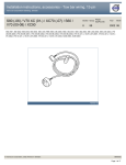
Installation instructions, accessories - Glass mounted GSM combined aerial
Volvo Car Corporation Göteborg, Sweden
XC90
XC90 2003, XC90 2004, XC90 2005, XC90 2006, XC90 2007, XC90 2008, XC90 2009, XC90 2010
© VolvoCar Corporation, 2002 Printed in Sweden
Section Group Weight(Kg/Pounds) Year
3
39
Month
2002 06
Replaces issue: 2001 12
8685982
Page 1 of 13
Installation instructions, accessories - Glass mounted GSM combined aerial
Volvo Car Corporation Göteborg, Sweden
Required tools
A0000162
R8802817
R3903907
© VolvoCar Corporation, 2002 Printed in Sweden
8685982
Page 2 of 13
Installation instructions, accessories - Glass mounted GSM combined aerial
Volvo Car Corporation Göteborg, Sweden
Any comments on this publication? Please contact your nearest dealer. Thank you!
Publication no: MA 8685982, Issue: 2002-06
Comments:..........................................................................................................
............................................................................................................................
............................................................................................................................
............................................................................................................................
............................................................................................................................
.............................................................................................................................
From:...................................................................................................................
Address:.............................................................................................................
Telephone no:................................................................................................... .
Telefax:...............................................................................................................
© VolvoCar Corporation, 2002 Printed in Sweden
8685982
Page 3 of 13
Installation instructions, accessories - Glass mounted GSM combined aerial
Volvo Car Corporation Göteborg, Sweden
INTRODUCTION
●
●
NOTE! Read through the whole installation instruction
before starting the work.
The front page gives the date of this edition and the edition it
replaces
Cars equipped with SRS/SIPS (Airbag)
Warning!
Extra care must be taken when working on cars equipped with SRS/SIPS
air bags. This is important to prevent:
1. Personal injury
The second page shows the tools needed for the installation and
the contents of the installation kit
2. Damage to or malfunction of the SRS/SIPS system.
●
The illustrations display the procedure in order of operation. The
order of operation is repeated in the text section
Work on the SRS/SIPS systems or related components must always be
carried out by an authorised Volvo workshop.
●
Cut out the text page in order to follow the illustrations and text at
the same time.
Is the car equipped with SRS (supplemental restraint system)?
●
Cars equipped with a driver's airbag have the letters "SRS" imprinted on
the centre panel of the steering wheel. Cars equipped with driver's and
passenger airbags are marked with "SRS" on both the steering wheel
centre panel and also on the dashboard close to the airbag.
If the car is equipped with SIPS (side impact protection system ) a "SIPS"
decal is marked on both the front seats.
Cars equipped with inflatable curtains have the marking "SRS" on one of
the panels along the posts on the inside of the car.
Cars equipped with SRS (supplemental restraint system) also have an
"SRS" decal on the front windscreen.
Do not damage the SRS wiring!
Do not trap, chafe, pierce or damage the SRS wiring. SRS wiring has
orange casing and/or is plaited.
Steering and front suspension
The contact reel in the SRS system can easily be damaged when
working on the steering wheel, steering shaft or steering gear. Refer to
the SRS (supplemental restraint system) Service Manual or service
instructions in VIDA for information on carrying out such work. This is to
prevent damage.
SRS warning lamp
If the SRS warning lamp lights after repairs have been carried out, take
the car to an authorised Volvo workshop.
SRS collision sensor control module
S60 / V70 (00-) / S80 / XC90
The collision sensor control module is located on the tunnel under the
© VolvoCar Corporation, 2002 Printed in Sweden
8685982
Page 4 of 13
Installation instructions, accessories - Glass mounted GSM combined aerial
Volvo Car Corporation Göteborg, Sweden
centre console, in front of the parking brake.
CAUTION!
The air bag inflation areas must not be obstructed. Never place
any objects, such as upholstery or accessories, within these
areas. The panels must be able to open in the correct manner at
the right time, otherwise there is an increased risk of personal
injury in the event of a collision.
CAUTION!
The ignition must be in position "0" and the key removed from
the ignition switch if any connector in the SRS system is to be
unplugged. Then wait at least one minute and disconnect the
battery negative lead before unplugging any of the connectors.
When work is completed, the ignition key must be turned to
position "II" before reconnecting the battery negative lead.
Glass mounted GSM combined aerial
Caution!
The aerial must be removed from the external base module if using a
carwash.
Note!
When installing the aerial the window must remain at a temperature of
at least +10°C.
© VolvoCar Corporation, 2002 Printed in Sweden
8685982
Page 5 of 13
Installation instructions, accessories - Glass mounted GSM combined aerial
Volvo Car Corporation Göteborg, Sweden
Preparations
1
●
Remove the right-hand side panel from the centre console. Pull off the panel
starting at the front edge. Then pull backwards until all the clips release.
R3903908
Preparations
2
●
A8800136
Applies to cars with power front seats
Position the right-hand front seat so that the panels over the front and right rear
seat mountings, and the small panel at the lower edge of the right-hand B-post
are not obstructed. They will be removed later after disconnecting the battery
negative lead.
●
Applies to all models
Turn the ignition key to position 0
●
Disconnect the battery negative lead.
Note!
Wait at least five minutes before disassembling the connectors or removing other
electrical equipment.
Preparations
3
●
Applies to cars with automatic gearboxes
Turn the ignition key to position II.
●
Applies to all models
Move the gear selector lever to its rearmost position
●
Carefully pry off the gear selector lever panel at the lower edge using a
weatherstrip tool. Pull the panel backwards to access the screws for the
dashboard environment panel.
R8504113
© VolvoCar Corporation, 2002 Printed in Sweden
8685982
Page 6 of 13
Installation instructions, accessories - Glass mounted GSM combined aerial
Volvo Car Corporation Göteborg, Sweden
Preparations
4
●
Remove the screws holding the bracket for the dashboard environment panel
and the control module
●
Pull out the bracket at the lower edge. Pull downwards from the top edge of the
centre console
●
Disconnect the connectors from the dashboard environment panel, control
module. If applicable disconnect the CD player and/or Mini disc player
connectors.
R8504051
Preparations
5
●
Remove the cover (1) on the left front mounting on the right-hand front seat by
prying off the front edge
●
Pry off the front edge of the right panel (2). Remove the panel.
R8504168
Preparations
6
●
Remove the panel on the right rear mounting on the right-hand front seat. Pry it
up slightly at the rear edge and then pull it back / upwards.
R8504241
Preparations
7
●
Carefully pry off and remove the panel above the joint between the right-hand
door sills, at the lower edge using a weatherstrip tool.
R8504169
© VolvoCar Corporation, 2002 Printed in Sweden
8685982
Page 7 of 13
Installation instructions, accessories - Glass mounted GSM combined aerial
Volvo Car Corporation Göteborg, Sweden
Preparations
8
●
Detach the sill trim panel for the right-hand front door. Pull off the panel starting at
the front edge until the clip releases. Continue backwards until the remaining
clips have released
●
Unhook the sill trim panel from the B-post panel.
R8504170
Preparations
9
●
Remove the panel in the right-hand front seat mounting on the right-hand seat in
the second row. Push up the catch (1) on the top. Pull the panel forward.
R8504171
Preparations
10
●
Fold the backrest on the right-hand seat in the second row forward as far as
possible. Slide the front seat forward as far as possible. (On cars with two
rows of seats, the second row is secured.)
●
Remove the cover (1) for the right rear seat mounting by prying off the rear
edge.
R8504172
Preparations
11A
Illustration A
●
●
R8504173
© VolvoCar Corporation, 2002 Printed in Sweden
Remove the sill trim panel for the right-hand rear door. Pull the rear edge until the
clips release. Continue forwards until the remaining clips have released.
Applies to cars with two rows of seats
On cars with two rows of seats the seat cannot be slid forwards. To remove
the sill trim panel; Start by folding the backrest forward when pulling the rear
edge of sill trim panel loose. Then reposition the backrest to raise the seat
cushion and provide more room for removing the sill trim panel. It is securely
positioned. Do not damage the panel and surrounding components.
8685982
Page 8 of 13
Installation instructions, accessories - Glass mounted GSM combined aerial
Volvo Car Corporation Göteborg, Sweden
11B
Illustration B
●
Unhook from the B-post panel and place in the second/third row of seats.
R8504174
Preparations
12A
●
●
R8503999
●
Applies to cars with three rows of seats and integrated carrier bag
holder on the under side of the centre floor hatch
Fold the rear centre floor hatch up
Detach the two straps from the panel underneath. Lift up the panel at the rear
edge. Fold the floor hatch back towards the panel and lift out the floor hatch and
the panel.
Applies to cars with three rows of seats without integrated carrier bag
holders
Lift up the centre rear floor hatch at the rear edge and lift it out.
12B
●
●
Applies to cars with two rows of seats
Remove the two centre floor hatches. First lift up slightly and then pull them loose
from the mountings at the front edge. If the rear centre floor hatch has a carrier
bag holder on the lower side, the floor hatch is secured by a strap on each of
the shorter sides of the storage box. These must be removed
Remove the two storage boxes from underneath.
R8902691
Preparations
13
●
Applies to all models
Remove the right-hand side floor hatch (1).
R8504158
© VolvoCar Corporation, 2002 Printed in Sweden
8685982
Page 9 of 13
Installation instructions, accessories - Glass mounted GSM combined aerial
Volvo Car Corporation Göteborg, Sweden
Preparations
14
●
Remove the folding side panel from the right-hand side in the cargo compartment.
R8504159
Preparations
15
●
Remove the cover and the screws for the rear headlining
●
Carefully pry off the panel at the rear edge using a weatherstrip tool
●
Pull the rear edge of the panel downwards until all clips in the inside have
released
●
Applies to cars with three rows of seats:Disconnect the connector for the
rear roof lighting. Pull the panel backward.
R8504084
Preparations
16
●
Carefully detach the D-post panels on the right and left-hand sides starting at the
top edge. Continue downwards until all three clips have released
●
Remove the panel by pulling upwards slightly and unhooking from the side panel.
If applicable, disconnect the connector for the D-post loudspeaker.
R8504086
Installing the combined aerial
17
R3903913
© VolvoCar Corporation, 2002 Printed in Sweden
●
Clean the surface where the inner base module is to be positioned using the
cleaning cloth from the kit
●
Wipe dry
●
Remove the backing from the inner base module
●
Position the inner base module horizontally on the side window, in line with the
rear end of the headlining. The upper rear corner of the inner base module must
be positioned edge to edge with the tinted area of the side widow as illustrated.
8685982
Page 10 of 13
Installation instructions, accessories - Glass mounted GSM combined aerial
Volvo Car Corporation Göteborg, Sweden
Installing the combined aerial
18
●
Install the aerial on the external base module.
A3902551
Installing the combined aerial
19
●
Clean the surface where the external base module is to be positioned using the
cleaning cloth from the kit
●
Wipe dry
●
Remove the backing from the external base module. Press the external base
module into place on the side window opposite the inner base module
●
Press hard on points 1, 2, 3, 4 and 5, in order, for 3-4 seconds
●
Ensure that the tape is sealed around the external base module. For optimum
adhesion, heat the glass. Use a hairdryer or similar.
R3903914
Cable routing and connecting the combined aerial
20
●
Route the aerial cable down along the existing wiring at the rear edge of the side
window down to the rear edge of the wheel arch
●
Clamp the aerial cable at the existing wiring using the tie straps from the kit.
R3903916
Cable routing and connecting the combined aerial
21
●
Applies to cars with two rows of seats
Route the aerial cable on the right-hand side of the cargo floor support, inside the
front edge of the floor carpet in the right-hand rear door opening. Continue along
the right-hand side of the car.
R3903909
© VolvoCar Corporation, 2002 Printed in Sweden
8685982
Page 11 of 13
Installation instructions, accessories - Glass mounted GSM combined aerial
Volvo Car Corporation Göteborg, Sweden
Cable routing and connecting the combined aerial
22
●
●
Applies to cars with three rows of seats
Insert a cable (1) at the rear edge of the right-hand side panel and along the
inside of the panel, above the mountings for the load securing eyelets and to the
front edge of the side panel
Tape the end to the aerial cable (2) at the cable. Pull the cable with the aerial
cable from the front edge of the side panel.
R3903910
Cable routing and connecting the combined aerial
23
●
Route the pre-routed aerial cable (1) on the reverse of the air duct (at the front
edge of the wheel arch) to the left-hand side of the seat belt lower mounting and
along the rear door sill. Continue inside the floor carpet to the front door opening
●
Clamp the cable harness in the hole in the front member for the seat mounting
and in the rear hole in the horizontal panel at the right-hand side of the seat. Use
the tie straps (2) (from the kit).
R3903911
Cable routing and connecting the combined aerial
24
●
Pull up the left and right sides of the carpet at the right-hand front seat slightly.
Insert a cable (1) underneath the carpet at the front edge of the air ducts on the
right-hand side of the centre console. Pull out the cable at the right-hand door sill
as illustrated
●
Tape the aerial cable (2) at the pre-routed cable. Route the cable to the righthand side of the centre console
●
Route the aerial cable up at the air ducts and pull along in the centre console
●
Connect the aerial cable to the cable from the carphone holder.
R3903912
25
Cable routing and connecting the combined aerial
●
© VolvoCar Corporation, 2002 Printed in Sweden
Reinstall:
the floor carpets
●
the bracket with dashboard environment panel and control module in the centre
console
●
the gear selector lever panel
●
the sill trim panels in the doors
●
the panel above the joints for the sill trim panels
●
the cover and panels for the seats
8685982
Page 12 of 13
Installation instructions, accessories - Glass mounted GSM combined aerial
Volvo Car Corporation Göteborg, Sweden
●
the right-hand side floor hatch
●
Reinstall the D-post panel and the headlining and any relevant connectors
●
Reinstall the folding panel.
Cable routing and connecting the combined aerial
26
●
Turn the ignition key to position II
●
Reconnect the battery negative lead
●
Reinstall the storage boxes and floor hatches
●
Reinstall the right-hand side panel on the centre console.
A8800137
© VolvoCar Corporation, 2002 Printed in Sweden
8685982
Page 13 of 13