1
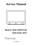
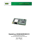
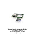
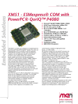
TITLE
Service Manual
LCD TV For 237-T11
Doc No.
Version
Page
SM_237-T11_19Nov07
1.2
31/72
7. Firmware upgrade
Olevia Firmware Updating Instructions
What does this do?
This process installs a new version of firmware that fixes or enhances your TV.
What products does this instruction apply to?
Model: Olevia 237, 437, 537 and 542
What do you need before installing?
1. A USB A to B cable.
2. A Computer with Microsoft® Windows® 2000 or Microsoft® Windows® XP
operating systems.
Important Notes:
1. Make sure that you are logged in to the computer as the Administrator or as a
user with installation rights.
2. Make sure that no other programs interfere with the installation, save your
work and close all other programs.
3. It is recommended to print the instructions to use as a reference before installing.
Loading Instructions:
1. Review the available downloads, the bugs fixed, and the new features added.
2. Create a directory to save the zip file and extract all files into the directory created.
3. Note: The following items are downloaded – make sure they are available under the same folder.
Company Confidential-DRAFT
TITLE
Doc No.
Version
Page
Service Manual
LCD TV For 237-T11
SM_237-T11_19Nov07
1.2
32/72
Firmware
Necessary for
Interface Tool to run.
Interface Tool
Firmware Download
Instructions
USB Driver
4. Connect USB cable from your computer to the TVs firmware upgrade port
located in the back of the unit.
Television
Computer
USB Cable
Note: You are require to install the USB driver to assure proper communication
between the computer and television. This executable file is in the
“MTK8202 USB2UART drive” folder.
PL-2303 Driver Installer.exe
Company Confidential-DRAFT
TITLE
Service Manual
LCD TV For 237-T11
Doc No.
Version
Page
SM_237-T11_19Nov07
1.2
33/72
5. Once you finish installing the USB driver, open the Interface Tool to begin downloading the
firmware.
Mtk_DL_V1.4 A_20060601.exe
6. Turn On the Television.
Company Confidential-DRAFT
TITLE
Service Manual
LCD TV For 237-T11
Doc No.
Version
Page
SM_237-T11_19Nov07
1.2
34/72
7. Press Step 1 to begin downloading the Firmware.
(Note: Will take roughly 15 seconds to begin loading firmware at which TV will turn off.)
8. When step 1 is complete, a message will prompt you to disconnect and connect the power cord.
(Press OK after you plug in the power cord.)
Company Confidential-DRAFT
TITLE
Service Manual
LCD TV For 237-T11
Doc No.
Version
Page
9. Connect Power Cable and continue to power on the television.
(Press the OK button after the television turns on.)
10. Press Step 2 to continue firmware loading.
(Note: Will take roughly 15 seconds to begin loading firmware.)
Company Confidential-DRAFT
SM_237-T11_19Nov07
1.2
35/72
TITLE
Service Manual
LCD TV For 237-T11
Doc No.
Version
Page
SM_237-T11_19Nov07
1.2
36/72
11. When step 2 is complete, a message will prompt you to disconnect and connect the power cord.
(Press OK after you plug in the power cord.)
12. Press the OK button and exit the Interface Tool.
TV/Computer.
Disconnect the USB cable from your
Company Confidential-DRAFT
TITLE
Service Manual
LCD TV For 237-T11
Doc No.
Version
Page
SM_237-T11_19Nov07
1.2
37/72
13. Turn TV ON and check that firmware was successfully loaded.
(Press Menu to activate the On Screen Display – Scroll UP/DOWN to SET UP and press
Enter – Scroll UP/Down to Firmware Version and press Enter.)
Press Enter
Press Enter
Make sure the last 4
digits matches with the
firmware uploaded.
Company Confidential-DRAFT
Service Manual
LCD TV For 237-T11
TITLE
Doc No.
Version
Page
SM_237-T11_19Nov07
1.2
38/72
8. EDID write in and ADC correction and Parameter Adjustment
8-1 EDID write in
8-1.1 EDID tools
1. PC(Notebook)
2. Software(EDID Write EEprom20060816.exe)and confirm Personal computer hard disk
Have 2 files (1. C:\EDID Editor(including Hex files) 2.C:\LCD TV\DATA(product and
record had No.)
8-1.2
EDIDPCBA
writetool、USB
in
3. EDID
cable、RS232 mini din、Print cable、VGA cable
Step 1
Step 2
Step 3
Step 4
MDA3
Step 5
Step 6
Step 7
1. Open Labview EDID Writ Eeprom20060816 file, and confirm software Keep Running.(Refer
Step 1)
2. choice RS-232 (PC System)Port No.(Refer Step 2),choice burn in type (Refer Step 3)
3. press Set Model button(Refer Step 4), and key in 237-T11. and confirm Scalar solution (Refer
Step 5)
4. confirm EDID Jig PCBA (printer port and USB A-B Line connect to PC, HDMI line to TV first ,
MinDim RS-232 to TV)
5. and then press Button(Refer Step 6), then open a save file path in widow.
operate Barcode scanner scan S/N stick No.
6. First write HDMI EDID code , if finish OK you can find green light.(Refer Step 7)
7. And have a message that change EDID Jip PCBA VGA Cable to TV.(HDMI line must leave
PCBA Jig.)
,if write OK you can fine green light
Company Confidential-DRAFT
and show the message
TITLE
Service Manual
LCD TV For 237-T11
Doc No.
Version
Page
SM_237-T11_19Nov07
1.2
39/72
that change next set.
8-2 ADC correction and Parameter adjustment
Photo 1
ADC correction and Parameter adjustment tools:
1. PC(Notebook)
2. CHROMA 2325
3. MINOLTA CA-210
4. Software(Gamma Calculator6A_Jason.exe)
8-2.1 ADC correction
1. Click the icon on the desk "Gamma Calculator" (please see
Photo 1), and then Photo 2 would show up.
2. Click the icon "Gamma Calculator" of Photo 2, and then
Photo 3 would show up.
3. Connect "RS232" &"VGA" with TV.
4. click the "arrow mark" (which is circle by red) in Photo 3,
and then click the icon "ADC" also in Photo 3 blue circle.
5. The window will show up with the instruction about
component, and then connecting component instead of
VGA port.
6. The ADC process is completed once the window with the
message "OK" shows up.
Photo 2
Photo 3
Attention:
:
1. Please make sure it's under "VGA Source" before
processing ADC.
Company Confidential-DRAFT
2. Please pay attention to different solution for
ATI/MTK8202/PW106 as Photo 3 green circle.
3. Please make sure the set-up for RS232 is correct.
TITLE
Service Manual
LCD TV For 237-T11
Doc No.
Version
Page
SM_237-T11_19Nov07
1.2
41/72
8-2.2 Parameter adjustment
Photo 4
1. Click the icon on the desk "Gamma Calculator" (please
see Photo 1), and then Photo 2 would show up.
2. Click the icon "Gamma Calculator" of Photo 2, and
then Photo 3 would show up.
3. Please follow (as Photo 4 blue circle) to choose the
solution & panel mode.
4. Connect the" RS232, USB, VGA changeful wire, and
audio wire" with TV. And then connect the other side
of VGA changeful wire with the pattern generator, and
set up the TV source under "VGA". And please locate
the "CA-210" on center of TV screen.
5. Click "BL" button, and the window with "Gamma
adjustment" message would show up. Please click
"OK" for next step. (as Photo 4 red circle)
6. Adjust the GAMMA (R;G;B) and then click the button
"Enter" after GAMMA adjustment is
completed.(Please follow Photo 5, 6)
7. Please check the result.
Photo 5
Photo 6
Attention:
:
Check pattern points for adjustment
(CHROMA PROGRAM:
:
:71 1360_FT_VGA ):
1. Check if the frame is damaged and if the size is
smaller than normal, or if those points in the 5
squares correspond well. (Photo 7)
2. Each gray bar should be identified with only pure
color.(Photo 8)
3. 256 Gray. L->R--->check if there is sync
(influenced by high frequency). (Photo 9)
Photo 7
Photo 8
Photo 9
Company Confidential-DRAFT