1
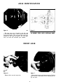
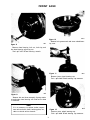
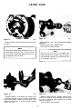
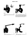
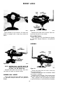
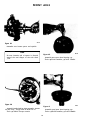
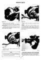
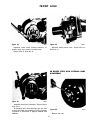
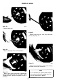
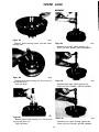
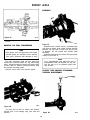
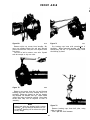
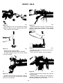
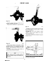
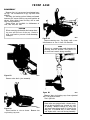
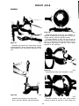
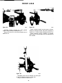
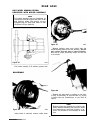
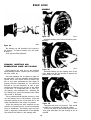
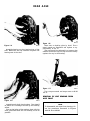
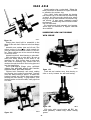
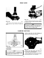
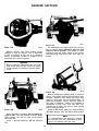
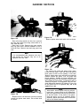
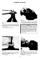
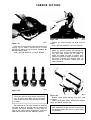
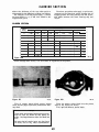
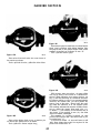
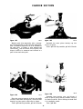
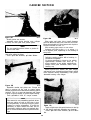
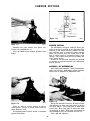
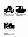
FRON T AXLE D-150-3 Sl£EVE Figure 2 1 D-150-2 ADAPTER REMOVER Figure 23 1009-21 Place knuckle in vise as shown. If bottom ball socket is equipped with a snap ring, remove as shown. 1009-23 Assemble ball socket tools as shown. Turn forc ing screw and push out top socket. Discard Ball Socket Tools-#D-150-1 Ball Joint Remover & Install er, #D-150-2 Adapter Remover, and #D-150-3 Sleeve. ASSEMBLY 1).}50-3 SLEEVE D-150-4 INSTAllER Sl£EVE Figure 22 0.150-3 SLEEVE 1009-22 NOTE: BOTTOM BALL SOCKET MUST BE REMOVED BEFORE THE TOP BALL SOCKET CAN BE REMOVED. Figure 24 Assemble ball socket tools as shown. Turn forc ing screw and push out bottom socket. 1009-24 (Lower ball socket does not have a cotter key hole in the stud end.) Assemble bottom socket into the knuckle. Make sure socket is straight. Assemble tools as shown. Turn forcing screw and push socket into knuckle as far as it will go. Tools-#D-150-1 Ball Joint Remover & Install er, #D-150-3 Sleeve, & #D-150-4 Sleeve Installer. DISCARD BALL SOCKET Tools-#D-150-1 Ball Joint Remover & Install er, #D-150-2 Adapter Remover , and #D-150-3 Sleeve. 10