1
MOOSUP VALLEY FIRE DEPARTMENT
FIRE APPARATUS SPECIFICATIONS
FIRE APPARATUS SPECIFICATIONS
Information for Contractors
Sealed proposals are desired from reputable makers of automobile fire apparatus in accordance with these specifications and with the
advertisement, a copy of which is attached, for the piece of apparatus listed as follows:
Fire Truck, aerial, apparatus body, and all other equipment in accordance with the following;
GENERAL REQUIREMENTS
Each bid must be accompanied by bidder’s accurate written specifications covering the apparatus and equipment, which it is
proposing to furnish and to which the apparatus furnished under the Contract must conform.
It is the intent of these specifications to cover the furnishing and delivery to the purchaser, complete apparatus equipped as specified.
All specifications herein contained are considered as minimum. Some items have been specified by brand name or model number.
These have been carefully selected because of their reliability, compatibility with present equipment, and local availability of parts.
No exceptions will be allowed relating to plumbing, gauge and types of materials, size of compartments, methods of construction, and
overall design features of the apparatus.
Exceptions taken in areas other than listed above must be listed on a separate page and marked "Exceptions To Specifications". Every
exception taken shall be listed as to page number and paragraph. Failure to provide the required exception list with the bid proposal
will be cause for rejection of that proposal.
Such details and other construction features not specifically covered herein shall conform with all State and Federal requirements, and
the NFPA Pamphlet No. 1901 "Standard for Automotive Fire Apparatus" in effect at the time the contract is signed.
RELIABILITY OF CONTRACTOR
Contractor shall furnish satisfactory evidence that he has the ability to construct the apparatus specified, and shall state in the bid
proposal the location of the factory where the apparatus is to be built, and also where future service work will be performed.
Proposals will only be considered which are submitted by full time fire apparatus manufacturers who are current members of the Fire
Apparatus Manufacturers Association (FAMA). FAMA is a nonprofit organization designed to keep fire truck manufacturers abreast
with latest technologies and governing standards, and to act as a liaison to the IAFC and NFPA. Bidder must have the ability to show
evidence of their affiliation to the FAMA in the bid proposal.
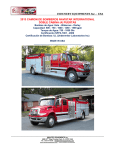
All bidders shall provide with their proposal, pictures of similar apparatus as that being specified, and the names of ten cities where
similar apparatus have been furnished. Bidders shall provide the name and telephone number of a contact person for each City listed.
Failure to provide a users list with the bid proposal shall be cause for rejection of that proposal.
SUBMISSION OF PROPOSALS
Each proposal shall be submitted in sequence with the attached specifications for ease of checking compliance of bids with bidder’s
specifications.
All proposals shall be submitted on company letterhead.
Each bid proposal shall be signed by an authorized representative of the manufacturing company being bid.
Moosup Valley Fire /Rescue
04/06/15
Page 1
MOOSUP VALLEY FIRE DEPARTMENT
FIRE APPARATUS SPECIFICATIONS
Any proposal which is not signed by a representative of the manufacturing company being bid or not submitted on company letterhead
will be immediately rejected.
PROPOSAL GUARANTEE
Each proposal must be accompanied by a Bidder's Bond or Cash in the amount of 10% of the bid submitted a proposal guarantee,
which it is agreed by the contractor will be forfeited in the event this proposal is accepted and the contract is not executed.
Bid bond shall be signed by an Officer of the manufacturing company being bid.
Personal or Company checks are not acceptable as a Bonding medium.
All bidders must have the ability to provide the requested Bidder's Bond and Performance Bonds when called for in these
specifications. Companies who are only able to provide Supply Bonds in lieu of Performance Bonds will not be considered.
INSURANCE REQUIREMENTS
Each bidder must submit with their bid proposal a Certificate of Insurance listing the proposed manufacturer's product liability
insurance coverage. General Liability Insurance limits shall have a minimum limit of $1,000,000 per occurrence and $2,000,000
General Aggregate limit. Umbrellas coverage shall have a minimum $15,000,000 limit. Submitted Certificate shall name the
apparatus manufacturer, insurance company, policy number, and effective dates of the insurance policy. Bids submitted without the
required Certificate, or for Certificates listing less than two (2) million dollars of general coverage, plus the ten (10) million dollar
umbrella coverage, will be considered non responsive and automatically rejected. No exceptions are allowed to the minimum
insurance coverage requirement.
The manufacturer shall maintain full insurance coverage on the purchaser's cab and chassis from time of first possession by the
manufacturer until the apparatus is delivered and accepted by the purchaser. No exceptions. Purchaser reserves the right to require
proof of insurance from the manufacturer's insurance carrier prior to entering into a contract for the apparatus.
DELIVERY AND OPENING OF PROPOSAL
Each proposal and all papers bound and attached thereto, together with the proposal guarantee, shall be placed in an envelope and
securely sealed therein. The envelope shall be marked "Bid On Fire Equipment".
Proposals will be received at or prior to the time set for the opening of bids. Proposals received after the "Bid Opening" will be
returned unopened.
The bids will be opened publicly and read aloud at the time and date stated on the advertisement for bids.
DRAWINGS
A CAD produced line drawing of the exact apparatus being proposed must be furnished with the bid. Since the blueprint drawing is
required of all bidders, any bid submitted without a drawing as specified will be considered non-responsive and automatically rejected.
Drawing must include the left side with chassis cab, right, and rear views of the vehicle. Drawing must be a large size "D", and shall
be a drawing of the exact apparatus as proposed, not a drawing of another similar unit. All submitted drawings will become a part of
the bid proposal.
REJECTION OF PROPOSALS
The right is reserved to reject any or all proposals or to accept such proposal as is in the best interest of the purchaser.
Moosup Valley Fire /Rescue
04/06/15
Page 2
MOOSUP VALLEY FIRE DEPARTMENT
FIRE APPARATUS SPECIFICATIONS
All bid requirements and specifications as written are considered minimum.
Bids will be rejected which substitute less substantial materials and/or methods of body construction than those specified. Since all
manufacturers have the ability to purchase the materials described as well as to shear, fabricate and assemble body panels as specified,
these areas are considered a strict requirement of the specification.
Purchaser does not, in any way, obligate itself to accept the lowest Bid.
Proposals may be rejected for any alteration, erasures, or penciled entries. No bidder may withdraw his proposal for at least 30 days
after the scheduled closing time for the receipt of bids.
Bidders taking "total exception" to these specifications are hereby advised that any such statement will result in immediate rejection of
the bid proposal.
COMPLETION DATE
Bidders shall indicate in their proposals the number of working days for delivery of the completed apparatus, from the date of bid
acceptance by the Manufacturer.
CARRYING CAPACITY
The GAWR and GCWR or GVWR of the chassis shall be adequate to carry the fully equipped apparatus including full water and
other tanks, the specified hose load, unequipped personnel weight, ground ladders, and a miscellaneous equipment allowance of 2000
pounds.
A permanent placard shall be affixed and visible to the driver, which states the maximum number of personnel the vehicle is designed
to carry.
The height of the fully loaded vehicle's center of gravity shall not exceed the chassis manufacturer's maximum limit.
WARRANTY
As a condition of the acceptance of the apparatus, the contractor shall furnish the following warranty:
We the manufacturing company, warrant each new piece of fire apparatus manufactured by us to be free from defects in material and
workmanship under normal use and service. Our obligation under this warranty is limited to repair or replacing, as the Company may
elect, any part or parts thereof which shall be returned to us with transportation charges prepaid and as to which examination shall
disclose to the company's satisfaction to have been defective, provided that such part or parts thereof shall be returned to us not later
than one year after delivery of said vehicle. Such defective part or parts will be returned or replaced free of charge and without charge
for reinstallation, to the original purchaser.
This warranty will not apply:
• To normal maintenance, service or adjustments.
• To any vehicle which has been repaired or altered outside of our factory in any way so as in our judgment, to affect its stability,
which has been subject to misuse, negligence, or accident, which has been operated at a speed exceeding the factory rated
speed, or which has been loaded beyond the factory rated load capacity.
Moosup Valley Fire /Rescue
04/06/15
Page 3
MOOSUP VALLEY FIRE DEPARTMENT
FIRE APPARATUS SPECIFICATIONS
• To the truck chassis and associated equipment furnished with the chassis, including, but not limited to; engine transmission,
axles, frame rails, alternator, batteries, or other trade accessories in as much as they are warranted separately by their respective
manufacturers.
This Warranty is in lieu of all other warranties expressed or implied and of all other obligations or liabilities on our part and we neither
assume nor authorize any other person to assume for us any liability in connection with the sale of our apparatus.
DESIGN REQUIREMENTS
Specified design features of the apparatus have been carefully selected because of their safety, integrity and consistency with existing
apparatus. It is expected that all bidders will adhere to the compartmentation layout, etc., since these features can be produced by all
fire apparatus manufacturers.
All aspects of the vehicle shall be properly engineered with priority given to firefighter safety, as well as ease of operation and
maintenance of the apparatus. The vehicle shall be free from hazardous protrusions, angles or sharp corners that might bring injury to
a firefighter or equipment. Previously delivered units will be judged for compliance to these factors.
All water, air, fuel, hydraulic and/or oil lines on the chassis and apparatus shall be properly located, and securely tie wrapped to
prevent scuffing or abrasion. Durable type grommets or loom material shall be used to protect the lines wherever a line passes through
the apparatus body or frame rail sections.
All grease fittings, bleeders, filler plugs, drains and check points shall be located so as to be easily accessible. No special tools shall be
required to access these components for normal service or maintenance of the vehicle.
All parts and components on the vehicle shall be positioned for ease of inspection, and recognition of wear or failure. Easily
removable access or cover plates shall be provided for all items requiring periodic service or adjustment. Access panels shall be of the
hinged or quick disconnect design-allowing ease of access.
Design of the apparatus shall be such that no disassembly of the body or any of its parts is required for normal maintenance.
All components of the chassis and apparatus shall be protected against rain, snow or other adverse weather conditions.
CONTRACT AWARD
Contract will be awarded to the most "responsible bidder", provided that bid is in the best interest of the purchaser.
When analyzing the bid proposals, and in recommending a successful bidder, superior design, workmanship, materials, operating
costs, location of factory, past experience, length of incorporation and compliance to specifications will be taken into consideration.
Purchaser reserves the right to waive any formality in the bids received once such waiver is in the best interest of the purchaser and,
also, to accept any item in the Bid found to be of superior quality or otherwise preferred by the Purchaser.
ACCEPTANCE TESTS AND REQUIREMENTS
Acceptance tests on behalf of the purchaser shall be prescribed and conducted prior to delivery or within 10 days after delivery, by the
manufacturer's representative in the presence of such person or persons as the purchaser may designate in the requirements for
delivery.
The apparatus, loaded with a full complement of hose and men, a full water tank, and equipment as specified in "Carrying Capacity"
on this page, shall meet the tests on paved roads, dry and in good condition. Tests shall be on the basis of two runs, in opposite
directions over the same route, the engine not operating in excess of the manufacturer's maximum rpm.
Moosup Valley Fire /Rescue
04/06/15
Page 4
MOOSUP VALLEY FIRE DEPARTMENT
FIRE APPARATUS SPECIFICATIONS
From a standing start, through the gears, the vehicle shall attain a true speed of 35-mph within 25 seconds. From a steady speed of 15mph the vehicle shall accelerate to a true speed of 35-mph within 30 seconds.
The vehicle shall attain a minimum top speed of 50-mph on a level road.
The apparatus shall be able to maintain a speed of at least 20-mph on any grade up to and including 6 percent.
Manufacturers pump test and Certification tests shall be conducted by the manufacturer in accordance with requirements of NFPA
#1901. Certificate of testing shall be furnished to the purchaser.
NOTE
Responsibility for the apparatus and all equipment shall remain with the contractor until the apparatus and equipment is delivered to
the purchaser.
FAILURE TO MEET TESTS
In the event the apparatus fails to meet the test requirements on first trial, a second trial may be made at the option of the Contractor
within thirty days of the date of the first trial. Such trials shall be final and conclusive and failure to comply with these requirements
shall be cause for rejection. Failure to make such changes as the Chief of the Fire Department and/or the purchaser may consider
necessary to conform to any clause of the specifications within thirty days after notice is given to the Contractor to make such changes
shall also be cause for rejection of the apparatus.
DOCUMENTATION
The manufacturer must supply at time of delivery, at least one copy of:
• Engine manufacturer's certified brake horsepower curve showing the maximum no load governed speed.
• Manufacturer's record of aerial construction details.
• If specified certification of inspection and testing by the Underwriter's Laboratories Incorporated.
• A copy of the apparatus manufacturer's approval for stationary pumping applications.
• Weight documents from a certified scale showing actual loading on the front axle, rear axle(s), and overall vehicle (with water
tank full but without personnel, equipment, or hose).
• At least two copies of the complete operation and maintenance manual covering the completed apparatus as delivered,
including the pump and firefighting equipment delivered with the apparatus.
NO EXCEPTIONS WILL BE ALLOWED TO ANY OF THE DOCUMENTATION REQUIREMENTS.
A test data plate shall be provided at the pump operator's position that gives the rated discharges and pressures together with the speed
of the engine as determined by the manufacturer's test for this unit. Plate must comply with requirements of NFPA #1901.
A permanent data plate shall be affixed in the drivers compartment specifying and quantity and type of the following fluids used in the
vehicle.
•
Engine Oil
Moosup Valley Fire /Rescue
04/06/15
Page 5
•
•
•
•
•
•
•
•
•
•
•
MOOSUP VALLEY FIRE DEPARTMENT
FIRE APPARATUS SPECIFICATIONS
Engine Coolant
Chassis Transmission Fluid
Drive Axle Lubrication Fluid
Air Conditioning refrigerant
Air Conditioning lubrication oil
Power steering fluid
Cab tilt mechanism fluid
Transfer case fluid
Equipment rack fluid
Air compressor system lubricant
Generator system lubricant
Permanent placards shall be affixed and visible to all seated occupants instructing the occupants to wear their seat belts.
A permanent placard shall be affixed to the rear step area to instruct that riding on the rear step is prohibited.
PAYMENT
Final payment for the apparatus shall be made at time of delivery of the completed vehicle. Due to insurance liability, the apparatus
will not be left at the purchaser's location without full acceptance and payment or prior agreement between the Purchaser and Bidder.
Final delivery price shall not include any Local, State or Federal taxes. The Bidder shall not be liable for any State or Federal
mandated tax or program after sale or delivery of the apparatus.
DELIVERED UNITS
The vehicle manufacturer shall provide a listing of ten (10) recently delivered units of similar design. The list shall include a contact
person and phone number who represents the purchaser.
MAX HEIGHT
The maximum height of the apparatus shall not exceed: 10'
OVERALL LENGTH
An overall length restriction has not been specified for this apparatus.
OVERALL WIDTH
An overall width restriction has not been specified for this apparatus.
WHEELBASE
A wheelbase restriction has not been specified for this apparatus.
ANGLE OF APPROACH
The angle of approach for the apparatus shall not be less than eight (8) degrees as specified by the current edition of NFPA 1901.
Moosup Valley Fire /Rescue
04/06/15
Page 6
MOOSUP VALLEY FIRE DEPARTMENT
FIRE APPARATUS SPECIFICATIONS
ANGLE OF DEPARTURE
The angle of departure for the apparatus shall not be less than eight (8) degrees as specified by the current edition of NFPA 1901.
TILT TESTING FACILITIES AND REQUIREMENTS
The apparatus, prior to acceptance, will be required to meet the stability test of the applicable NFPA Automotive Fire Apparatus
Standard. The final and completed vehicle shall be tilt-tested to the applicable standards and photographed to ensure that this
procedure and certification can be verified. Each bidder shall have the facilities to perform these tests at the manufacturing site. The
bidder shall own the facilities to perform the above test, and shall not contract with an outside agency to have these tests performed on
this apparatus.
INSPECTION TRIPS
One (1) Inspection trip for two (2) Fire Department personnel shall be made to the facility during the course of construction of the
apparatus. Successful bidder shall consult with Fire Department committee chairperson as to the proper timing of the inspection
trip(s). Air travel (for distances over 250 miles), meals, and lodging expenses shall be included. BIDDER SHALL INDICATE
INTENTION TO PROVIDE THE REQUIRED INSPECTION TRIP(S) IN THE PROPOSAL PACKET.
DELIVERY
Final delivery of the completed apparatus shall be made F.O.B. Fire Department Headquarters.
DEMONSTRATION
Fire Department personnel shall be properly instructed as to the proper use of the entire apparatus including, but not
limited to, chassis, fire pump system, the apparatus and all equipment. The demonstration shall be made by a factory
trained Specialist who shall be responsible for complete instruction as to operation and maintenance of the chassis,
and the completed vehicle.
A demonstration specialist shall remain at the Fire Department for a sufficient amount of time to provide thorough
instruction to all personnel, or as instructed by Chief of the Department.
BUMPER TO BUMPER WARRANTY
Each new motorized fire apparatus shall be warranted for a period of ONE YEAR from the date of delivery, except for chassis and
other components noted herein.
Under this warranty the manufacturer agree to furnish any parts to replace those that have failed due to defective material or
workmanship where there is no indication of abuse, neglect, unusual or other than normal service providing that such parts are, at the
option of the manufacturer, made available for our inspection at our request, returned to our factory or other location designated by us
with transportation prepaid within thirty days after the date of failure or within one year from the date of delivery of the apparatus to
the original purchaser, whichever occurs first, and inspection indicates the failure was attributed to defective material or workmanship.
The warranty on the chassis and chassis supplied components, storage batteries, generators, electrical lamps and other devices subject
to deterioration is limited to the warranty of the manufacturer thereof and adjustments for the same are to be made directly with the
manufacturer by the customer.
This warranty will not apply to any fire apparatus that has been repaired or altered outside our factory in any way, which in our
opinion might affect its stability or reliability.
Moosup Valley Fire /Rescue
04/06/15
Page 7
MOOSUP VALLEY FIRE DEPARTMENT
FIRE APPARATUS SPECIFICATIONS
This warranty shall not apply to those items that are usually considered normal maintenance and upkeep services: including, but not
limited to, normal lubrication or proper adjustment of minor auxiliary pumps or reels.
FIRE PUMP WARRANTY
EXPRESS WARRANTY: Hale Products, Incorporated (“Hale”) hereby warrants to the original buyer that products manufactured by
Hale are free of defects in material and workmanship for a period of five (5) years from the date the product is first placed into service
or five and one-half (5-1/2) years from date of shipment by Hale, whichever period shall be first to expire. Within this warranty period
Hale will cover parts and labor for the first two (2) years and parts only for years three (3) through five (5).
STAINLESS STEEL PLUMBING WARRANTY
The manufacturer shall warrant that the stainless steel plumbing components and ancillary brass fittings used in the construction of the
water/foam plumbing system shall be warranted for a period of ten (10) years.
ALUMINUM BODY WARRANTY - FIVE YEAR
The manufacturer shall warrant that the all aluminum body be structurally sound and will remain free from corrosion perforation for a
period of FIVE (5) years.
GALVANIZED SUBFRAME WARRANTY
The manufacturer shall warrant that the new hot dip galvanized body sub frame is structurally sound and free of all structural defects
of both material and workmanship and further warrants that it will maintain such structural integrity for the duration of ownership by
the original purchaser.
PAINT WARRANTY FIVE YEAR
The PPG paint performance guarantee will cover the areas of the vehicle finished with the specified product for a period of FIVE (5)
years beginning the day the vehicle is delivered to the purchaser.
COMPLETE PRINTED MANUAL
The manufacturershall provide with the vehicle upon delivery, one (1) complete delivery manual. This manual shall be in a notebook
type binder, with reference tabs for each section of the vehicle. A companion compact disk (CD) with all of the printed material in an
electronic format (Adobe Acrobat PDF) shall be provided.
Within each section shall be:
•
•
•
•
•
•
•
•
•
•
Individual component manufacturer instruction and parts manuals
Warranty forms for the body
Warranty forms for all major components
Warranty instructions and format to be used in compliance with warranty obligations
Wiring diagrams
Installation instruction and drawings for major parts
Visual graphics and electronic photos for the installation of major parts
Necessary normal routine service forms, publications and components of the body portion of the apparatus
Technical publications for training and instruction on major body components
Warning and safety related notices for personnel protection
Moosup Valley Fire /Rescue
04/06/15
Page 8
MOOSUP VALLEY FIRE DEPARTMENT
FIRE APPARATUS SPECIFICATIONS
•
Cab and chassis manuals on parts, service and maintenance shall be provided
"ON-LINE" SERVICE MANUAL SUPPORT
As part of the standard delivery manual, the manufacturer shall give a password-protected link to the end user, allowing access to the
manufacturers' database on service parts. The internet-based system shall allow the end
user to access the major component supplier's service parts listing such as Hale, Waterous, Akron, etc. This shall be accomplished
with simplistic point and click features on the manufacturer line item within the "stripper" or "line item sheet". This will include,
automatic updates, printable schematics and manufacturer's web links and is available in the commercially available format of Adobe
Acrobat Reader to access these documents.
Parts Listings within Manuals
The manuals will include cross-reference part numbers from the manufacturer part number to the vendor parts. Example: This will
allow for reference between individual parts and complete installation assemblies as completed by the body builder. The manuals will
list all components of the vehicle that includes a vendor part utilized in a complete installation via the manufacturer’s "line item sheet"
or "stripper" utilized to manufacture the completed vehicle. These are "As Built" and proposals with "typical" or "generic" manuals
will be rejected.
Illustrative Schematics within Manuals
The Manufacturer shall include installation diagrams and drawings of all major sub assemblies. This will include components such
as hydraulic ladder rack assemblies, pump panels, tanks, fire pumps, etc. The drawings shall be linked via an Internet based service
program, in an electronic format from the manufacturers "stripper" (line item listing) of the manufacturing document.
Digital Images within Manuals
In addition to two and three-dimensional installation drawings, the Manufacturer shall make accessible, via an internet based link,
the actual photos of the installed components listed within the "stripper" or line sheet. This will include, but not limited to wiring
terminals, main body distribution strips, fire pump shifting, auxiliary components, etc.
Installation Instructions within Manuals
"Work instructions" or "installation instructions" shall be included with the service manuals. These documents shall be accessible via
a web-based link to the individual vehicle manufactured. The work instructions shall give systematic instructions of the component
installation process.
Automatic Updates of Manuals and Parts Listings
The online manuals will include automatic updates that are accessible via the web link. When clicking on the part within the
manufacturer’s stripper or line sheet, it will allow the end user to access the component manufacturer website for updated information.
This will allow for latest parts and service components from the individual part manufacturer or vendor.
Electrical Schematics
To maintain the vehicles electrical systems, the manufacturer shall provide to the purchaser the instructional manuals, complete
electrical information and schematics on the vehicle. The electrical information shall be provided as follows:
Moosup Valley Fire /Rescue
04/06/15
Page 9
MOOSUP VALLEY FIRE DEPARTMENT
FIRE APPARATUS SPECIFICATIONS
Wiring Systems 12 and 120 Volt:
•
•
•
Graphic symbols for electrical diagrams.
Wire labeling, imprinting codes and index.
Computer generated electrical schematics indicating the circuit number, wire size, switches, circuit breaker and terminals on
the vehicle.
INTERNATIONAL CHASSIS - 2016 7400 SFA 4X4
Model Profile
The chassis shall be a 2016 International 7400 SFA 4X4 (SR525)
Wheelbase:
The wheelbase for the chassis shall be 238.00, CA: 119.10, Axle to Frame: 75.00
ENGINE
The engine shall be a {Navistar N9} EPA 10, SCR, 330 HP @ 2000 RPM, 950lb-ft Torque @
1200 RPM, 2200 RPM
TRANSMISSION
The transmission shall be an Allison 3000EVS with 5th Generation Controls; Close Ratio, 5-Speed;
With Overdrive, Includes Oil Level Sensor, With Provision for PTO, Less Retarder, Max. GVW N/A
Omit Item (Clutch & Control)
FRONT AXLE
The front axle shall be aMeritor MX-16-120 Single Reduction, 16,000-lb Capacity
REAR AXLE
The rear axle shall be a Meritor RS-30-185} Single Reduction, Standard Track, 30,000-lb Capacity.
CAB:
The cab shall be a four door, conventional 6-Man Crew Cab
TIRES, FRONT:
Two (2) 315/80R22.5 G751 MSA (GOODYEAR) 484 rev/mile, load range L, 20 ply tires shall be provided.
TIRE, REAR:
Four (4) 315/80R22.5 G751 MSA (GOODYEAR) 484 rev/mile, load range L, 20 ply tires shall be provided.
Moosup Valley Fire /Rescue
04/06/15
Page 10
MOOSUP VALLEY FIRE DEPARTMENT
FIRE APPARATUS SPECIFICATIONS
FRONT SUSPENSION:
The front suspension shall be SPRING Parabolic, Taper Leaf; 16,000-lb Capacity; With Shock Absorbers
REAR SUSPENSION:
A Vari-Rate; 31,000-lb Capacity, With 4500 lb Auxiliary Rubber Spring suspension shall be provided.
FRAME RAILS:
The chassis frame shall be Heat Treated Alloy Steel (120,000 PSI Yield); 10.125" x 3.580" x 0.312"
(257.2mm x 90.9mm x 8.0mm); 480 .0" (12192) Maximum OAL
FRAME REINFORCEMENT:
Outer "C" Channel, Heat Treated Alloy Steel (120,000 PSI Yield); 10.813" x 3.892" x 0.312";
(274.6mm x 98.9mm x 8.0mm); 480.0" (12192mm) Maximum OAL frame reinforcement shall be
provided
BUMPER, FRONT:
The front bumper shall be Full Width, Aerodynamic, Chrome Plated Steel
BRAKE SYSTEM:
The Brake System shall be a AIR Dual System for Straight Truck Applications Including:
: BRAKE LINES Color and Size Coded Nylon
: DRAIN VALVE Twist-Type
: DUST SHIELDS, FRONT BRAKE
: DUST SHIELDS, REAR BRAKE
:GAUGE, AIR PRESSURE (2) Air 1 and Air 2 Gauges; Located in Instrument Cluster
: PARKING BRAKE CONTROL Yellow Knob, Located on Instrument Panel
: PARKING BRAKE VALVE For Truck
: QUICK RELEASE VALVE Bendix On Rear Axle for Spring Brake Release: 1 for 4x2, 2 for 6x4
: SLACK ADJUSTERS, FRONT Automatic
: SLACK ADJUSTERS, REAR Automatic
: SPRING BRAKE MODULATOR VALVE R-7 for 4x2, SR-7 with relay valve for 6x4
ANTILOCK BRAKES:
A Bendix AntiLock Brake System Full Vehicle Wheel Control System Shall be provided
AIR DRYER:
A Bendix AD-IP} With Heater Shall be provided with air dryer location outside left rail, back of cab.
STEERING WHEEL:
The steering wheel shall be a 2-Spoke, 18" Diam., Black
Moosup Valley Fire /Rescue
04/06/15
Page 11
MOOSUP VALLEY FIRE DEPARTMENT
FIRE APPARATUS SPECIFICATIONS
ENGINE EXHAUST BRAKE:
An Engine Exhaust Brake for Navistar N9/10 16 Engines shall be provided.
ELECTRICAL SYSTEM:
The Chassis will be equipped with 12-Volt, Standard Equipment Including:
: BATTERY BOX Steel with Plastic Lid
: DATA LINK CONNECTOR For Vehicle Programming and Diagnostics In Cab
: FUSES, ELECTRICAL SAE Blade-Type
: HAZARD SWITCH Push On/Push Off, Located on Top of Steering Column Cover
: HEADLIGHT DIMMER SWITCH Integral with Turn Signal Lever
: HEADLIGHTS (2) Sealed Beam, Round, with Chrome Plated Bezels
: JUMP START STUD Located on Positive Terminal of Outermost Battery
: PARKING LIGHT Integral with Front Turn Signal and Rear Tail Light
: RUNNING LIGHT (2) Daytime, Included With Headlights
: STARTER SWITCH Electric, Key Operated
: STOP, TURN, TAIL & B/U LIGHTS Dual, Rear, Combination with Reflector
: TURN SIGNAL SWITCH Self-Cancelling for Trucks, Manual Cancelling for Tractors, with Lane
Change Feature
:WINDSHIELD WIPER SWITCH 2-Speed with Wash and Intermittent Feature (5 Pre-Set Delays), Integral
withTurn Signal Lever
: WINDSHIELD WIPERS Single Motor, Electric, Cowl Mounted
: WIRING, CHASSIS Color Coded and Continuously Numbered
: CIGAR LIGHTER Includes Ash Cup
: HORN, ELECTRIC (2) Disc Style
: IGNITION SWITCH Keyless
ALTERNATOR
A Leece-Neville 12 Volt, 320 Amp. Capacity,shall be provided.
BATIERY SYSTEM
Three (3) Maintenance-Free, 12-Volt Batteries
VEHICLE DATA RECORDER
The vehicle shall be equipped with a Vehicle Data Recorder with the Display Mounted in Overhead Console
SEATBELT WARNING SYSTEM
A Seatbelt Warning System Including Seat Belt Switches and Seat Sensors for all Belted Positions in the
CabShall be provided.
GRILLE EMBER SCREEN
A Grille Ember Screen Shall be Mounted to Grille and Cowl Tray to Keep Hot Embers out of Engine and
HVAC
Moosup Valley Fire /Rescue
04/06/15
Page 12
MOOSUP VALLEY FIRE DEPARTMENT
FIRE APPARATUS SPECIFICATIONS
FUEL TANK
The Fuel Tank Shall be a Top Draw; D Style, Non Polished Aluminum, 19" Deep, 50 U.S. Gal., 189 L
Capacity, with Quick Connect Outlet, Mounted Left Side, Under Cab.
DEF TANK
A 7 U.S. Gal. 26.5L Capacity, Diesel Exhaust Fluid Tank will be provided. The Tank Shall be Frame Mounted
Outside on the Left Rail, Under the Cab.
LOW VOLTAGE ELECTRICAL SYSTEM SPECIFICATIONS
The electrical system shall include all panels, electrical components, switches and relays, wiring harnesses and other electrical
components. The electrical equipment installed by the apparatus manufacturer shall conform to current automotive electrical system
standards, the latest Federal DOT standards, and the requirements of the applicable NFPA standards.
All wiring shall be stranded copper or copper alloy conductors of a gauge rated to carry 125 percent of the maximum current for the
protected circuit. Voltage drops in all wiring from the power source to the using device shall not exceed 10 percent. The wiring and
wiring harness and insulation shall be in conformance to applicable SAE and NFPA standards. The wiring harness shall conform to
SAE J-1128 with GXL temperature properties. All exposed wiring shall be protected in a loom with a minimum 289 degree
Fahrenheit rating. All wiring looms shall be properly supported and attached to body members. The electrical conductors shall be
constructed in accordance with applicable SAE standards, except when good engineering practice requires special construction.
The wiring connections and terminations shall use a method that provides a positive mechanical and electrical connection and shall be
installed in accordance with the device manufacturer's instructions. Electrical connections shall be with mechanical type fasteners and
large rubber grommets where wiring passes through metal panels.
The wiring between the cab and body shall be joined using Deutsche type connectors or an enclosed in a terminal junction panel area.
This system will permit body removal with minimal impact on the apparatus electrical system. All connections shall be crimp-type
with insulated shanks to resist moisture and foreign debris such as grease and road grime. Weather-resistant connectors shall be
provided throughout to ensure the integrity of the electrical system.
There shall be no exposed electrical cabling, harnesses, or terminal connections located in compartments, unless they are enclosed in a
junction box or covered with a removable electrical panel. The wiring shall be secured in place and protected against heat, liquid
contaminants and damage. Wiring shall be uniquely identified every three-inches (3") by color coding or permanent marking with a
circuit function code and identified on a reference chart or electrical wiring schematic per requirements of applicable NFPA #1901
standards.
The electrical circuits shall be provided with low voltage overcurrent protective devices. Such devices shall be accessible and located
in required terminal connection locations or weather resistant enclosures. The overcurrent protection shall be suitable for electrical
equipment and shall be automatic reset type and meet SAE standards. All electrical equipment, switches, relays, terminals, and
connectors shall have a direct current rating of 125 percent of maximum current for which the circuit is protected. The system shall
have electro-magnetic interference suppression provided as required in applicable SAE standards.
The electrical system shall include the following:
• Electrical terminals in weather exposed areas shall have a non-conductive grease or spray applied. A corrosion preventative
compound shall be applicable to all terminal plugs located outside of the cab or body.
• The electrical wiring shall be harnessed or be placed in a protective loom.
Moosup Valley Fire /Rescue
04/06/15
Page 13
MOOSUP VALLEY FIRE DEPARTMENT
FIRE APPARATUS SPECIFICATIONS
• Holes made in the roof shall be caulked with silicone. Large fender washers shall be used when fastening equipment to the
underside of the cab roof.
• Any electrical component that is installed in an exposed area shall be mounted in a manner that will not allow moisture to
accumulate in it.
• A coil of wire must be provided behind an electrical appliance to allow them to be pulled away from mounting area for
inspection and service work.
• All lights that have their sockets in a weather exposed area shall have corrosion preventative compound added to the socket
terminal area.
The warning lights shall be switched in the chassis cab with labeled switches in an accessible location. Individual rocker switches
shall be provided only for warning lights provided over the minimum level of warning lights in either the stationary or moving modes.
All electrical equipment switches shall be mounted on a switch panel mounted in the cab convenient to the operator. The warning light
switches shall be of the rocker type. For easy nighttime operation, an integral indicator light shall be provided to indicate when the
circuit is energized. All switches shall be appropriately identified as to their function.
A single warning light switch shall activate all required warning lights. This switch will allow the vehicle to respond to an emergency
and "call for the right of way". When the parking brake is applied, a "blocking right of way" system shall automatically activate per
requirements of the applicable NFPA standards. All "clear" warning lights shall be automatically turned off upon application of the
parking brake.
NFPA REQUIRED TESTING OF ELECTRICAL SYSTEM
The apparatus shall be electrically tested upon completion of the vehicle and prior to delivery. The electrical testing, certifications, and
test results shall be submitted with delivery documentation per requirements of the applicable NFPA standards. The following
minimum testing shall be completed by the apparatus manufacturer:
1. Reserve capacity test:
The engine shall be started and kept running until the engine and engine compartment temperatures are stabilized at normal operating
temperatures and the battery system is fully charged. The engine shall be shut off and the minimum continuous electrical load shall be
activated for ten (10) minutes. All electrical loads shall be turned off prior to attempting to restart the engine. The battery system shall
then be capable of restarting the engine. Failure to restart the engine shall be considered a failed test.
2. Alternator performance test at idle:
The minimum continuous electrical load shall be activated with the engine running at idle speed. The engine temperature shall be
stabilized at normal operating temperature. The battery system shall be tested to detect the presence of battery discharge current. The
detection of battery discharge current shall be considered a test failure.
3. Alternator performance test at full load:
The total continuous electrical load shall be activated with the engine running up to the engine manufacturer's governed speed. The
test duration shall be a minimum of two (2) hours. Activation of the load management system is permitted during this test. However, if
an alarm sounds due to excessive battery discharge, as detected by the system requirements in the NFPA standards, or a system
voltage of less than 11.7 volts dc for more than 120 seconds is present, the test has failed.
Moosup Valley Fire /Rescue
04/06/15
Page 14
MOOSUP VALLEY FIRE DEPARTMENT
FIRE APPARATUS SPECIFICATIONS
4. Low voltage alarm test:
Following the completion of the above tests, the engine shall be shut off. The total continuous electrical load shall be activated and
shall continue to be applied until the excessive battery discharge alarm activates. The battery voltage shall be measured at the battery
terminals. With the load still applied, a reading of less than 11.7 volts dc for a 12 volt system shall be considered a test failure. The
battery system shall then be able to restart the engine. Failure to restart the engine shall be considered a test failure.
NFPA REQUIRED DOCUMENTATION
The following documentation shall be provided on delivery of the apparatus:
a. Documentation of the electrical system performance tests required above.
b. A written load analysis, including:
1. The nameplate rating of the alternator.
2. The alternator rating under the conditions.
3. Each specified component load.
4. Individual intermittent loads.
WEATHER RESISTANT ELECTRICAL JUNCTION BOX
The electrical junction or terminal boxes shall be weather resistant and located away from water spray conditions. In addition, the
main body junction panel shall house the automatic reset breakers and relays where required. The main body junction panel shall be
located in the pump compartment.
LOAD MANAGER 2
The apparatus shall be equipped with a Kussmaul model 091-79 Automatic Load Shedding System for performing continuous
electrical load management. The Load Manager shall have the following features:
•
•
•
•
Monitor 12-volt system and detect low voltage.
Capability to control two (2) loads.
Automatic reset when voltage rises.
Adjustable voltage setpoint.
The load manager shall be protected against reverse polarity and shorted outputs, and be enclosed in an enclosure to enhance EMI/RFI
protection. The manufacturer shall provide for all electrical loads in excess of the NFPA minimum electrical requirements that exceed
the alternator output.
HIGH IDLE SYSTEM
There shall be a high idle system furnished and installed on the apparatus. The high idle system shall have an on/off switch located in
the chassis on the switch console. The system shall have an interlock that will disable the solenoid if the parking brake is not
completely set.
Moosup Valley Fire /Rescue
04/06/15
Page 15
MOOSUP VALLEY FIRE DEPARTMENT
FIRE APPARATUS SPECIFICATIONS
ELECTRICAL CONSOLE WITH EMERGENCY LIGHT SWITCH PANEL – THERMAL COATED
An electrical console shall be constructed of .125" black thermoplastic coated smooth aluminum material, and mounted in the cab of
the truck chassis. Console shall be designed and installed between the driver and passenger seats. The top face of the console shall be
designed as the switch panel for all emergency light switches. The switch panel shall be hinged for easy access to the switch
connections.
All emergency light switches shall be lighted, rocker style. Switches shall be internally lit when the switch circuit is in the on position.
A plug-in identification label is to be provided and installed adjacent to each rocker switch with backlighting provided behind the
label.
SWITCHES
A rocker style internally lighted switch shall be provided and wired through a heavy-duty relay to activate power to the emergency
lights. The emergency lights shall be activated by a single "MASTER SWITCH" on the electrical console.
BATTERY CHARGER AND AIR COMPRESSOR
One (1) Kussmaul Pump Plus 1200 model #091-187-12-R-B1 battery charger and air compressor system shall be installed. The 120
volt compressor system shall be designed to maintain the air pressure in the chassis brake system whenever the pressure drops below a
predetermined level.
The battery charger shall be supplied from the 120 volt shore power receptacle and be a fully automatic high output charging system.
The unit shall be mounted in a clean dry area and will be accessible for service and/or maintenance.
BATTERY CHARGER DISPLAY
One (1) Kussmaul single battery bank voltage display shall be supplied with the charger.
SHORE POWER PLUG
The shore power plug shall be located in the step area below the left front cab door of the commercial chassis.
AUTO-EJECT
A Kussmaul "Super Auto-Eject" 20-amp automatic disconnect device shall be provided and installed on the 110 volt shoreline
connection complete with weatherproof cover and matching plug. The Auto-Eject shall be activated by the chassis starter switch to
disconnect the plug. The Super Auto-Eject shall be completely sealed to prevent contamination of the mechanism by inclement
weather and road conditions. The Super Auto-Eject shall have an internal switch to open and close the AC circuit after the mating
connector is inserted and before the connector is removed.
AIR HORNS
Two (2) 24.5" Stuttertone chrome plated air horns shall be recess mounted into the front bumper with one positioned on each side. An
air protection valve shall be provided in the air horn piping that will not allow the chassis air brake system to drop below 90 PSI.
AIR HORN LANYARD
One (1) dual roof mounted pull cord shall be installed to activate the air horn system. The pull cord shall be installed within easy reach
of the driver and officer.
Moosup Valley Fire /Rescue
04/06/15
Page 16
MOOSUP VALLEY FIRE DEPARTMENT
FIRE APPARATUS SPECIFICATIONS
PUMP ENCLOSURE LIGHTS
One (1) incandescent work light shall be provided in the pump enclosure. The control switch shall be mounted on the light head.
BACKUP CAMERA SYSTEM
One (1) Safety Vision camera system SV-CLCD-70BA-KIT with cables and mounting hardware shall be furnished utilizing one SV625B color camera with audio which provides a wide field of view and picture quality. The 7” color monitor shall be a SV-CLCD70BA supporting up to two cameras and has a compact flat screen that takes minimal space. The monitor does not require a separate
control box.
An audible feature shall be included with the camera system.
MAP LIGHT
One (1) Federal 18" map light with a goose neck light arm shall be installed on the right side of dash. The light shall be 12 volt and
have an on-off switch located on the base of the light.
RADIO ANTENNA BASE
Three (3) radio antenna base shall be supplied and installed on the apparatus, the antenna coax terminating in the cab. The location
shall be determined by the customer.
MARKER LIGHTS
LED marker lights shall be installed on the vehicle in conformance to the Department of Transportation requirements.
MARKER LIGHTS
Two (2) Britax P/N L427.203.L12V flex rubber arm style LED Clearance lights shall be mounted on the rear of the body, one each
side. These lights are in addition to the lights required by the DOT.
LICENSE PLATE BRACKET
One (1) license plate bracket shall be provided at the rear bumper. The bracket shall have a light and shall be chrome plated.
TAIL LIGHTS
Two (2) Whelen M6 LED tail/brake lights shall be provided. The rectangular 4"x6" light shall be red.
TURN SIGNALS
Two (2) Whelen M6 LED turn signals with populated sequential chevron arrow shall be provided.
MID BODY LED TURN SIGNALS
Two (2) mid body LED turn signals shall be provided. The location of the turn lights shall be at mid-body near the rear wheel axle.
BACKUP LIGHTS
Two (2) Whelen Series M6 LED backup lights shall be installed on the rear of the apparatus body. The dimensions shall be 4" x 6"
Moosup Valley Fire /Rescue
04/06/15
Page 17
MOOSUP VALLEY FIRE DEPARTMENT
FIRE APPARATUS SPECIFICATIONS
and the lens color shall be clear.
FOUR LIGHT HOUSING
Two (2) chrome plated tail light housings shall be supplied. Each housing shall be designed to hold four (4) Whelen M6 rear lights
located at the lower rear corners of the body.
FRONT BUMPER GROUND LIGHTS
Two (2) ground lights LED lights shall be installed under the front bumper.
PUMP PANEL GROUND LIGHTS
Two (2) LED ground lights shall be installed under the pump panel running boards. One (1) light shall be located on the driver's side
and one (1) light located on the officer's side of the apparatus.
REAR STEP GROUND LIGHTS
Two (2) LED ground lights shall be installed under rear step of the apparatus.
The ground lights shall automatically activate when the parking brake is applied.
REAR TAILBOARD LIGHTS
Two (2) LED step lights with clear lens shall be installed to illuminate the step surfaces at the rear of the apparatus body.
STEP LIGHT
Two (2) LED step light with clear lens shall be installed to illuminate the side running boards.
The step/walkway light switch shall be installed and wired to the parking brake.
DECK LIGHTS – REAR
The deck lights shall be installed at the rear of the hose bed. One (1) Unity Model #AG spotlight and one (1) Unity Model #AG
floodlight, with 35 watt bulbs shall be installed. The lights shall have an "on-off" switch.
SCENE LIGHT
Six (6) Fire Research model SPA900-Q70 surface mount light shall be installed. The light shall be mounted with four (4) screws to a
flat surface. It shall be 6 3/4" high by 9" wide and have a profile of less than 1 3/4" beyond the mounting surface. Wiring shall extend
from a weatherproof strain relief at the rear of the light.
The light shall have twenty-four (24) white LEDs that generate a rated 4600 lumens at 12 or 24 volts DC. The lens shall redirect the
light along the vehicle and out onto the working area. The light housing shall be aluminum with a chrome colored bezel.
SCENE LIGHT LOCATION
Two (2) scene light shall be located on the left side of the apparatus body.
Moosup Valley Fire /Rescue
04/06/15
Page 18
MOOSUP VALLEY FIRE DEPARTMENT
FIRE APPARATUS SPECIFICATIONS
SCENE LIGHT LOCATION
Two (2) scene light shall be located on the right side of the apparatus body.
SCENE LIGHT LOCATION
Two (2) scene light shall be located on the rear of the apparatus body.
SCENE LIGHT SWITCHING
One (1) scene light switch with indicator shall be installed on the cab main switch panel to control the left side scene light(s). The
switch shall be labeled "LEFT SCENE".
SCENE LIGHT SWITCHING
One (1) scene light switch with indicator shall be installed on the cab main switch panel to control the right side scene light(s). The
switch shall be labeled "RIGHT SCENE".
SCENE LIGHT SWITCHING
One (1) scene light switch with indicator shall be installed on the cab main switch panel to control the rear scene light(s). The switch
shall be labeled "REAR SCENE".
SCENE LIGHT SWITCHING
The rear scene lights shall activate automatically upon placing the transmission into reverse.
ELECTRIC SIREN
One (1) Code 3 Model #3692 V-Con electronic siren shall be mounted in the cab. The unit shall feature an electronic air horn, wail,
yelp, hi-lo siren and shall have a hard wired microphone.
SPEAKER
One (1) Federal Signal DynaMax Model #ES100 100-watt speaker shall be installed.
SPEAKER
One (1) stainless steel grille shall be installed on the speaker.
SPEAKER LOCATION
The siren speaker shall be installed on the apparatus bumper extension, as determined by the body manufacturer.
LIGHTBAR
One (1) integral sunvisor and low profile modular lightbar shall be installed. The lightbar shall consist of three (3) modules. There
shall be one (1) center module with four (4) red linear LED's, two (2) white linear LED's and three (3) amber DOT lights. The two
corner modules, each with two (2) red linear LED's and one (1) amber DOT light. The lightbar modules shall be installed on the cab
mounted visor.
Moosup Valley Fire /Rescue
04/06/15
Page 19
MOOSUP VALLEY FIRE DEPARTMENT
FIRE APPARATUS SPECIFICATIONS
The sunvisor shall be an original equipment sunvisor designed to fit the specified chassis and not a "one size fits all" style visor. This
will ensure that the integral visor / lightbar shall be mounted securely and will match the style of the chassis cab and shall be painted
to match the roof color.
LIGHTBAR ACTIVATION
The front upper light bar activation shall be wired into the master warning switch.
CHROME FLANGES
Each light shall be mounted with a Whelen Model M6FC chrome flange.
UPPER WING FRONT WARNING LIGHTS
One (1) pair of Whelen model M6 LED warning lights shall be installed, one each side one the front of the chassis cab upper grille
area. The dimensions of the lights shall be 4-5/16" x 6-3/4".
INNER GRILLE WARNING LIGHTS
One (1) pair of Whelen model M7 LED warning lights shall be installed, one each side on the front of the chassis grille, inboard
position. The dimensions of the lights shall be 3-3/8" x 7-5/8".
INTERSECTION WARNING LIGHTS
One (1) pair of Whelen model M6 LED warning lights shall be installed one each side of the chassis cab. The dimensions of the lights
shall be 4-5/16" x 6-3/4".
LOWER MID-BODY WARNING LIGHTS
One (1) pair of Whelen model M6 LED warning lights shall be installed , one each side of the apparatus, mid-body. The dimensions
of the lights shall be 4-5/16" x 6-3/4".
LOWER REAR SIDE WARNING LIGHTS
One (1) pair of Whelen model LINZ6 LED warning lights shall be installed, one each side of the apparatus body, towards the rear of
the body. The dimensions of the lights shall be 2" x 4".
UPPER REAR WARNING LIGHTS
One (1) pair of Whelen model #RB6T Rota-Beam warning lights shall be installed on the upper corners of the rear body. The unit
shall have dual rotators with total dimensions of 7" high x 8" deep and shall have one red lens and one amber lens.
REAR WARNING LIGHT MOUNTING
The upper rear lights shall be mounted on cast aluminum stanchions attached to the apparatus body, one on each side.
LOWER REAR WARNING LIGHTS
One (1) pair of Whelen model M6 LED warning lights shall be installed, one each side on the lower rear of the apparatus body. The
dimensions of the lights shall be 4-5/16" x 6-3/4".
Moosup Valley Fire /Rescue
04/06/15
Page 20
MOOSUP VALLEY FIRE DEPARTMENT
FIRE APPARATUS SPECIFICATIONS
TRAFFIC ARROW LIGHT
One (1) Whelen Model #TAL85 Traffic Advisor shall be installed. The light shall be equipped with eight (8)
LED lights measuring 46" in length. The unit shall be mounted at the rear of the apparatus body. The Traffic Advisor control head
shall be mounted inside the cab and be accessible by the driver and officer.
The traffic arrow light shall be surface mounted below the rear intermediate step of the apparatus body.
FLUID DATA PLAQUE
One (1) fluid data plaque containing required information shall be provided based on the applicable components for this apparatus,
compliant with NFPA Standards:
•
•
•
•
•
•
•
Engine oil
Engine coolant
Chassis transmission fluid
Drive axle lubricant
Power steering fluid
Pump transmission lubrication fluid
Other NFPA applicable fluid levels or data as required
Location shall be in the driver's compartment or on driver's door.
DATA & WARNING LABELS
HEIGHT LENGTH & WEIGHT
A highly visible label indicating the overall height, length, and weight of the vehicle shall be installed in the cab dash area.
CAB SEATING POSITION LIMITS
The label shall also include the seating positions for firefighters. A weight allowance of 250 pounds for each shall be factored into the
gross vehicle weight rating of the chassis.
NO RIDE LABEL
One (1) "NO RIDERS" label shall be applied on the vehicle at the rear step area or other applicable areas. The label shall warn
personnel that riding in or on these areas, while the vehicle is in motion is prohibited.
CAB SEATING POSITION LIMITS
One (1) label shall be installed in the cab to indicate seating positions for firefighters. A weight allowance of 250 pounds for each shall
be factored into the gross vehicle weight rating of the chassis.
Moosup Valley Fire /Rescue
04/06/15
Page 21
MOOSUP VALLEY FIRE DEPARTMENT
FIRE APPARATUS SPECIFICATIONS
HELMET WARNING TAG
One (1) label shall be installed in the cab, visible from each seating position. The label shall read "CAUTION: DO NOT WEAR
HELMET WHILE SEATED." Helmets must be properly stowed while the vehicle is in motion according to the current edition of
NFPA 1901.
REAR TOWING PROVISIONS
There shall be two tow eyes furnished under the rear of the body and attached directly to each chassis frame rail. There shall be a
reinforcement spreader bar connecting the two tow eyes. Tow eyes are to be constructed of 3/8" plate steel with a 4" I.D. hole, large
enough for passing through a tow chain end hook.
The tow plates shall be painted black.
BUMPER EXTENSION
The chassis frame shall be extended 18" with reinforced steel angle and structural channel by the body builder. The extension shall be
designed to support the bumper and other equipment to be installed.
FRONT BUMPER GRAVELSHIELD
An 18" front to rear filler panel constructed from NFPA compliant, slip resistant aluminum tread plate shall be provided on the front
chassis frame extension. The extension shall be covered on the top and sides, up to the level of front bumper and shall be reinforced to
support one (1) firefighter (approximately 250 pounds) and the equipment specified to be installed.
FRONT BUMPER COMPARTMENT
One (1) recessed fire hose compartment constructed from smooth aluminum shall be installed in the center of the front bumper
extension. Water drain holes shall be drilled in the bottom.
BUMPER COMPARTMENT DOOR
One (1) raised aluminum tread plate door for the front bumper compartment shall be supplied. The door shall have a minimum 1" lips
on all sides surrounding the entire compartment opening, a stainless steel hinge at the rear and a latch to secure the compartment.
BUMPER COMPARTMENT DOOR SHOCK
A gas shock shall be supplied to hold the front bumper compartment door in the open position.
HUB AND LUG NUT COVERS
The apparatus shall have chrome or stainless steel hub and lug nut covers on the front and single rear axles.
TIRE PRESSURE INDICATOR
There shall be a tire pressure indicator at each tire’s valve stem on the vehicle that shallindicate if there is insufficient pressure in the
specific tire.
EXHAUST SYSTEM
The chassis exhaust shall be modified and redirected to the right side of the apparatus and will exit ahead of the rear wheel.
Moosup Valley Fire /Rescue
04/06/15
Page 22
MOOSUP VALLEY FIRE DEPARTMENT
FIRE APPARATUS SPECIFICATIONS
EXHAUST HEAT SHIELD
A heat shield shall be installed under the body in the areas where the exhaust system is routed.
REAR MUD FLAPS
One (1) pair of black mud flaps shall be installed behind the rear wheels.
CAB STEP ENCLOSURE LEFT
The left side of the International 4-door chassis shall be equipped with a modular step/fuel tank enclosure constructed from slip
resistant aluminum tread plate to conform with applicable NFPA standards. The step/enclosure is to completely cover the fuel tank,
and is to include a radius cut-out allowing access to the fuel tank fill. The entire step/enclosure is to be of a one piece design, bolted in
place for ease of removal.
Heavy channel steel underbody supports shall be provided to support the right and left side cab entrance steps. Supports shall be
attached directly to the chassis frame rails, and shall provide adequate support to the steps to minimize flex and distortion.
CAB STEP ENCLOSURE RIGHT
The right side of the International 4-door chassis shall be equipped with a modular step/fuel tank enclosure constructed from slip
resistant aluminum tread plate to conform with applicable NFPA standards. The step/enclosure is to completely cover the fuel tank,
and is to include a radius cut-out allowing access to the fuel tank fill. The entire step/enclosure is to be of a one piece design, bolted in
place for ease of removal.
Heavy channel steel underbody supports shall be provided to support the right and left side cab entrance steps. Supports shall be
attached directly to the chassis frame rails, and shall provide adequate support to the steps to minimize flex and distortion.
The overlay shall be provided with a storage compartment. A hinged door with latch shall be provided on the storage compartment.
CAB STEP ENCLOSURE GRATING LEFT
The cab step enclosure shall be provided with a multi-directional aggressive gripping surface incorporated into the aluminum diamond
plate and shall comply with NFPA #1901 standards.
CAB STEP ENCLOSURE GRATING RIGHT
The cab step enclosure shall be provided with a multi-directional aggressive gripping surface incorporated into the aluminum diamond
plate and shall comply with NFPA #1901 standards.
SCBA BRACKET
Three (3) BostromSecureAllTM, SCBA bracket shall be provided for installation in the cab mounted SCBA seat. The bracket can be
adjusted to fit any size bottle or brand of SCBA currently on the market. An NFPA approved and patented auto-lock mechanism holds
the SCBA in place for a secure fit in all directions. The integrated one-touch release handle is located in the seat cushion for a quick
and easy exit.
INTERIOR CABINET
There shall be one (1) full height storage cabinet installed on the back wall of the interior cab. The cabinet shall be constructed of
smooth aluminum plate. The cabinet shall have approximate interior dimensions of 36" Wide x 18" Deep x Full Height.
Moosup Valley Fire /Rescue
04/06/15
Page 23
MOOSUP VALLEY FIRE DEPARTMENT
FIRE APPARATUS SPECIFICATIONS
The cabinet shall be equipped with a roll-up door constructed of anodized aluminum.
The cabinet’s exterior shall have an unpainted D/A orbital sander finish.
The cabinet’s interior shall have a natural finish.
Two (2) adjustable shelf shall be installed in the interior cab compartment. The shelf shall be constructed from aluminum.
INTERIOR CABINET LIGHTS
Two (2) vertically mounted LED strip lights shall be installed inside the compartment. The lights shall have a polycarbonate lens to
eliminate breakage from impact and eliminate heat build up and each light shall be approximately 30" in length.
The compartment light shall be mounted in the door jamb to illuminate the compartment interior.
The compartment light will be controlled by a magnetic "On-Off" switch located on each compartment door.
DUAL PURPOSE AIR HOSE CONNECTION
One (1) female compressed air fitting shall be installed on the driver's side exterior of the cab. The fitting shall be designed for
connection to an external air source to maintain the air brake pressure and to allow the chassis air to be utilized for low volume tools
while the engine is running. A 1/4 turn valve shall be installed adjacent to the fitting to control the airflow. The fitting and the valve
shall be labeled accordingly.
1500 GPM FIRE PUMP SPECIFICATIONS
The centrifugal type fire pump shall be a Hale model QMAX midship mounted with a rated capacity of 1500 GPM. The pump shall
meet NFPA 1901 requirements.
The pump shall be certified to meet the following deliveries:
1500 GPM @ 150 PSI
1500 GPM @ 165 PSI
1050 GPM @ 200 PSI
750 GPM @ 250 PSI
HALE QMAX SINGLE STAGE PUMP
A Hale model Q-MAX single stage pump shall be designed to mount within a pump enclosure and shall be split-drive shaft driven.
The pump shall be driven by a driveline from the truck transmission. The engine shall provide sufficient horsepower and RPM to
enable the pump to meet and exceed its rated performance.
The entire pump, suction and discharge passages shall be hydrostatically tested to a pressure of 600 PSI. The pump shall be tested at
the pump manufacturer's factory to the performance specs as outlined by the applicable sections of the NFPA 1901 standard. The
pump shall be free from objectionable pulsation and vibration.
PUMP BODY
The pump body and related parts shall be fine grain alloy cast iron, with a minimum tensile strength of 30,000 PSI. All metal moving
parts in contact with water shall be of high quality bronze or stainless steel. The pump body shall be horizontally split, on a single
plane in two sections for easy removal of entire impeller assembly including wear rings and bearings from beneath the pump without
disturbing piping or the mounting of the pump in chassis.
Moosup Valley Fire /Rescue
04/06/15
Page 24
MOOSUP VALLEY FIRE DEPARTMENT
FIRE APPARATUS SPECIFICATIONS
IMPELLERS
The pump shall have one double suction impeller. The pump body shall have two opposed discharge outlet volute cutwaters to
eliminate radial unbalance. Pump impeller shall be hard, fine grain bronze of the mixed
flow design; accurately machined and individually balanced. The vanes of the impeller intake eyes shall be of sufficient size and
design to provide ample reserve capacity utilizing minimum horsepower.
Impeller clearance rings shall be bronze, easily renewable without replacing impeller or pump volute body, and shall be of wraparound double labyrinth design for maximum efficiency.
PUMP SHAFT
Pump shaft shall be rigidly supported by three bearings for minimum deflection. One (1) high lead bronze sleeve bearing shall be
located immediately adjacent to the impeller (on side opposite the gearbox). The sleeve bearing shall be lubricated by a force fed,
automatic oil lubricated design, pressure balanced to exclude foreign material. The remaining bearings shall be heavy-duty, deep
groove ball bearings in the gearbox and they shall be splash lubricated.
The pump shaft shall be heat-treated, electric furnace, corrosion resistant stainless steel to be super-finished with galvanic corrosion
protection for longer shaft life. Pump shaft must be sealed with double-lip oil seal to keep road dirt and water out of the gearbox.
PUMP TRANSMISSION
Pump transmission shall be of sufficient size to withstand 16,000 lb./ft. of torque of the engine. The drive unit shall be designed of
ample capacity for lubrication reserve and to maintain the proper operating temperature.
The gearbox drive shafts shall be of heat-treated chrome nickel steel and be at least 2-3/4" in diameter, on both the input and output
drive shafts. They shall withstand the full torque of the engine.
All gears both drive and pump, shall be of highest quality electric furnace chrome nickel steel. Bores shall be ground to size and teeth
integrated and hardened, to give an extremely accurate gear for long life. An accurately cut spur design shall be provided to eliminate
all possible end thrust.
PUMP MOUNTING
The pump shall be bolted to steel angles in the pump module, using grade 8 bolts.
DRIVELINES
Hollow-tube drivelines and universals shall be properly matched to the engine and transmission output torque ratings.
FIRE PUMP MECHANICAL WATER SEAL
The Hale fire pump shall have a high quality, self-adjusting, maintenance free mechanical seal.
ELECTRIC/PNEUMATIC PUMP SHIFT
The pump shift shall be an air operated and shall incorporate an air cylinder with an electric actuating switch to shift from road to
pump and back. The power shift control valve shall be mounted in the cab. The fire pump-shift system shall be equipped with a
means to prevent unintentional movement of the control device from its set position.
The system shall include a nameplate indicating the chassis transmission shift selector position to be used for pumping and located so
that it can be easily read from the driver's position.
Moosup Valley Fire /Rescue
04/06/15
Page 25
MOOSUP VALLEY FIRE DEPARTMENT
FIRE APPARATUS SPECIFICATIONS
The system shall include applicable the NFPA interlocks, pump shift and OK TO PUMP indicator lights in the cab and pump panel.
The fire pump system shall be equipped with an interlock system shall be provided to ensure that the pump drive system components
are properly engaged in the pumping mode of operation so that the pumping system can be safely operated from the pump operator's
position.
If applicable, the secondary braking device shall be automatically disengaged for pumping operations.
FIRE PUMP ANODE
One (1) Hale Fire Pump Alloy Anode(s) shall be installed to reduce corrosion. The anode shall be a bolt-in or screw-in type and
easily replaceable.
FIRE PUMP PRIMER
The fire pump shall be equipped with a Hale model #ESP oil-less electrically driven priming pump. The unit shall be a positive
displacement vane type. A Hale PV priming control shall be located at the pump operator's panel and when pulled it shall open the
priming valve and start the priming motor.
The pump shall be capable of taking suction and discharging water with a lift of 10 feet in not more than 30 seconds with the pump
dry, through 20 feet of suction hose of appropriate size. The priming system shall comply with applicable sections of NFPA
standards.
FIRE PUMP SPLIT SHAFT DRIVESHAFTS AND INSTALLATION
The mid-ship split shaft fire pump shall be installed and shall include installation of the fire pump, modification and/or fabrication of
new drivelines and all pump-mounting brackets. The drive shaft(s) shall be spin balanced prior to final installation.
UNDERWRITERS LABORATORIES FIRE PUMP TEST
The pump shall undergo an Underwriters Laboratories Incorporated test per applicable sections of NFPA standards, prior to delivery
of the completed apparatus.
The UL acceptance certificate shall be furnished with the apparatus on delivery.
FIRE PUMP TEST LABEL
A fire pump performance and rating label shall be installed on the fire apparatus pump panel. The label shall denote levels of pump
performance and testing completed at factory. These shall include GPM at net pump pressure, RPM at such level, and other pertinent
data as required by applicable NFPA standards. In addition, the pressure control device, tank to pump flow tests, and other required
testing shall be completed.
In addition, the entire pump, suction and discharge passages shall be hydrostatically tested to a pressure as required by applicable
NFPA standards. The pump shall be fully tested at the pump manufacturer's factory to the performance specifications as outlined by
applicable NFPA standards. Pump shall be free from objectionable pulsation and vibration.
If applicable, the fire pump shall be tested and rated as follows:
100% of rated capacity at 150 pounds net pressure.
70% of rated capacity at 200 pounds net pressure.
50% of rated capacity at 250 pounds net pressure.
Moosup Valley Fire /Rescue
04/06/15
Page 26
MOOSUP VALLEY FIRE DEPARTMENT
FIRE APPARATUS SPECIFICATIONS
INTAKE RELIEF/DUMP VALVE
One (1) TFT A18 series, 2-1/2" intake relief/dump valve preset at 125 psi shall be permanently installed on the suction side of the fire
pump. The valve shall have an adjustment range of 75 psi to 250 psi, and shall be designed to automatically self-restore to a nonrelieving position when excessive pressure is no longer present.
Discharge side of the intake relief valve shall be plumbed away from the pump operator.
FIRE PUMP COOLING
The fire pump shall be equipped with 3/8" cooling line from the pump to the water tank. This re-circulation line shall be controlled
by a pump panel control valve with nameplate label noting it as the "fire pump bypass cooler". There shall be a check valve installed
in the pump cooler line to prevent tank water from back flowing into the pump when it is not in use.
CHASSIS ENGINE HEAT EXCHANGER COOLING SYSTEM
The apparatus shall be equipped with a heat exchanger for supplementary chassis engine cooling during fire pump operations. A
manually opened valve, mounted at the operator's panel, shall direct water from the fire pump to the heat exchanger that is mounted in
the engine radiator cooling hose. The system shall provide cooling water from the fire pump to circulate around the engine radiator
coolant without mixing or coming in
direct contact with the engine coolant. The complete installation shall be done by the fire apparatus manufacturer.
A nameplate label shall be installed on the pump panel noting "engine cooling system" with "on-off" opening directions noted.
PUMP ANODES
There shall be sacrificial, zinc anodes in the pump steamer ports which shall protect the pump and piping from electrolysis. These
anodes shall also act as screens.
PUMP PLUMBING SYSTEM
The fire pump plumbing system shall be of rigid stainless steel pipe or flexible piping with stainless steel fittings. Mechanical
grooved couplings shall be installed to permit flexing of the plumbing system and allow for quick removal of piping or valves for
service. Flexible hose couplings shall be threaded stainless steel or mechanical grooved coupling connections.
The fire pump and plumbing shall be hydrostatically tested in compliance to applicable sections of NFPA standards. The test results
shall be included in the delivery documentation.
FIRE PUMP MASTER DRAIN
The fire pump plumbing system and fire pump shall be piped to a single push-pull type master pump drain assembly.
ADDITIONAL LOW POINT DRAINS
The plumbing system shall be equipped with additional low point manually operated drain valves to allow total draining of the fire
pump plumbing system. These valves shall be accessible from the side of the vehicle and labeled.
Moosup Valley Fire /Rescue
04/06/15
Page 27
MOOSUP VALLEY FIRE DEPARTMENT
FIRE APPARATUS SPECIFICATIONS
Innovative Controls ¾” cast bronze quarter-turn drain/bleeder valve shall be installed. The valve shall be complete with a chrome
plated bronze ball, reinforced teflon seals, and blow-out proof stem rated to 600 PSI. A chrome plated zinc handle shall be provided
on each drain valve complete with a recessed ID label provision. The handle shall lift, to open and push down, to close.
FIRE PUMP & PLUMBING SYSTEM PAINTING
The fire pump and plumbing system shall be painted by the fire apparatus manufacturer. The fire pump and the plumbing shall be
painted metallic silver.
HOSE THREADS
The hose threads shall be National Standard Thread (NST) on all base threads on the apparatus intakes and discharges.
RIGHT SIDE -- 6" UNGATED INTAKE
One (1) 6" ungated suction intake shall be installed on the right side pump panel to supply the fire pump from an external water
supply. The intake shall be provided with a removable screen.
One (1) 6" chrome plated cap shall be provided. The threads shall be NST and the cap shall be equipped long handles.
GATED 6" INTAKE -- LEFT SIDE PUMP PANEL
One (1) 6" gated suction intake shall be installed behind the left side pump panel to supply the fire pump from an external water
supply. A Hale model MIV-E master intake valve with dump/relief shall be provided.
A pressure dump/relief valve shall be included that is factory preset at 125 PSI and field adjustable from 75 to 250 PSI. The pressure
dump/relief valve shall provide over-pressure protection for the suction hose even when the intake valve is closed. The outlet of the
dump/relief valve shall be 2.5" in diameter to allow directing the discharge flow away from the pump operator's position.
A 12-volt DC electric motor with remote switching shall operate the valve located on the pump operator's panel. The valve shall have
a position indicator provided to indicate whether the valve is open, closed or traveling from one position to another. The valve shall be
provided with a gear actuator that will cycle the valve from OPEN to CLOSED position in no less than three (3) seconds. The gear
actuator and electrical connections shall be sealed units designed to provide protection from the pump compartment environment to
insure long life and reliable operation. A manual override control shall be installed on pump panel.
The intake shall be provided with manual drain valves. An inlet fitting with 6" NST thread shall be provided, complete with a
removable strainer screen.
One (1) 6" chrome plated cap shall be provided. The threads shall be NST and the cap shall be equipped long handles.
LEFT SIDE -- 2-1/2" GATED INTAKE
One (1) 2-1/2" gated suction intake shall be installed on left side pump panel to supply the fire pump from an external water supply.
The control valve shall be a quarter turn ball valve and shall have 2-1/2" NST female thread of chrome plated brass.
The valve shall be equipped with one (1) manually operated, swing-type manual control located adjacent the intake. The valve shall
be equipped with a color-coded name plate.
The intake shall be equipped with a ¾" drain and bleeder valve. A nameplate label and removable screen shall be installed.
Moosup Valley Fire /Rescue
04/06/15
Page 28
MOOSUP VALLEY FIRE DEPARTMENT
FIRE APPARATUS SPECIFICATIONS
One (1) 2-1/2" chrome plated plug shall be provided. The threads shall be NST and the plug shall be equipped rocker lugs and chain
or cable securement.
RIGHT SIDE -- 2-1/2" GATED INTAKE
One (1) 2-1/2" gated suction intake shall be installed on right side pump panel to supply the fire pump from an external water supply.
The control valve shall be a quarter turn ball valve and shall have 2-1/2" NST female thread of chrome plated brass.
The valve shall be equipped with one (1) manually operated, swing-type manual control located adjacent the intake. The valve shall
be equipped with a color-coded name plate.
The intake shall be equipped with a ¾" drain and bleeder valve. A nameplate and removable screen shall be installed.
One (1) 2-1/2" chrome plated plug shall be provided. The threads shall be NST and the plug shall be equipped rocker lugs and chain
or cable securement.
WATER TANK TO PUMP LINE
One (1) 4" water tank to fire pump line shall be provided with a full flow quarter turn ball valve, 4" piping, and with flex hose and
stainless steel hose clamps. The tank to pump line shall be equipped with a check valve to prevent pressurization of the water tank.
The line shall be flow tested during the fire pump testing and shall meet applicable requirements of NFPA standards.
The 4" valve shall be equipped with one (1) Akron manually operated, hand-wheel control with dial type position indicator. A colorcoded name plate shall be installed adjacent to the valve control.
FIRE PUMP TO WATER TANK FILL LINE
One (1) 2" fire pump to water tank refill and pump bypass cooler line shall be provided. The valve shall be a full flow quarter turn
ball valve with 2" piping and flex hose to tank. The valve control handle shall have a nameplate located near the valve control.
The specified valve shall be an Akron 8000 Series two-inch (2") valve with a stainless ball.
One (1) Akron valve equipped with a manually operated pull rod, with quarter-turn locking feature shall be provided on the intake.
The handle shall be equipped with a color-coded name plate.
2" DISCHARGE FRONT RIGHT SIDE BUMPER
One (1) 2" discharge shall be installed at front right side bumper area with brass swivel outlet with 1-1/2" NST male threads. The
valve control shall be on pump panel and a nameplate label provided at valve control area.
The specified valve shall be an Akron 8000 Series two-inch (2") valve with a stainless ball.
For valve actuation, the specified discharge shall be equipped with a side mount valve control. The ergonomically designed 1/4 turn
push-pull T-handle shall be chrome plated zinc with recessed labels for color coding and signage. The gear-control rod, double
laminated locking clips, and rod housing shall be stainless steel and provide true positive lock that will eliminate valve drift. Bronze
and Teflon impregnated stainless steel bushings in both ends of rod housing shall eliminate rod deflection, never need lubrication and
ensure consistent long-term operation.
The control assembly shall include a decorative chrome-plated zinc panel mounted bezel with recessed color-coded label.
Moosup Valley Fire /Rescue
04/06/15
Page 29
MOOSUP VALLEY FIRE DEPARTMENT
FIRE APPARATUS SPECIFICATIONS
A Class 1 automatic type 3/4" bleeder valve shall be installed
The plumbing shall be flexible hose with abrasion resistant support mountings. Auxiliary low point drains shall be provided on the
discharge line.
The hose connection for the front discharge shall be swivel type located above the front bumper deck level.
THREE (3) 1-1/2" CROSSLAY DISCHARGES
Three (3) pre-connect 1-3/4" hose crosslays shall be installed over pump enclosure, with quarter turn 2" diameter ball valves. The
outlets shall be a 2" NPT female swivel x 1-1/2" male with NST hose threads.
The specified valves shall be an Akron 8000 Series two-inch (2") valve with a stainless ball.
For valve actuation, the specified discharge shall be equipped with a side mount valve control. The ergonomically designed 1/4 turn
push-pull T-handle shall be chrome plated zinc with recessed labels for color coding and signage. The gear-control rod, double
laminated locking clips, and rod housing shall be stainless steel and provide true positive lock that will eliminate valve drift. Bronze
and Teflon impregnated stainless steel bushings in both ends of rod housing shall eliminate rod deflection, never need lubrication and
ensure consistent long-term operation.
The control assembly shall include a decorative chrome-plated zinc panel mounted bezel with recessed color-coded label.
The crosslayhosebeds shall have smooth aluminum sides. The hosebed decking shall be constructed with slots integrated into the
hosebed.
Each hosebed shall provide for a minimum capacity of 200 feet of 1-3/4" diameter double jacket hose with nozzle, for hose provided
by the fire department.
2-1/2" CROSSLAY DISCHARGE
One (1) pre-connect 2-1/2" hose crosslay shall be installed over the pump enclosure with a quarter turn 2-1/2" diameter ball valve.
The outlet shall be a 2-1/2" NPT female swivel x 2-1/2" male NST hose threads.
The specified valve shall be an Akron 8000 Series two and one half-inch (2-1/2") valve with a stainless ball.
For valve actuation, the specified discharge shall be equipped with a side mount valve control. The ergonomically designed 1/4 turn
push-pull T-handle shall be chrome plated zinc with recessed labels for color coding and signage. The gear-control rod, double
laminated locking clips, and rod housing shall be stainless steel and provide true positive lock that will eliminate valve drift. Bronze
and Teflon impregnated stainless steel bushings in both ends of rod housing shall eliminate rod deflection, never need lubrication and
ensure consistent long-term operation.
The control assembly shall include a decorative chrome-plated zinc panel mounted bezel with recessed color-coded label.
The hosebed decking shall be constructed with slots integrated into the hosebed floor.
The hose bed shall provide for a minimum capacity of 150 feet of 2-1/2" diameter double jacket hose with the hose and nozzle
provided by the fire department.
CROSSLAY HINGED COVER WITH END FLAPS
The crosslayhosebed shall be equipped with a single aluminum diamond plate hinged cover with vinyl end flaps with hook & loop
Moosup Valley Fire /Rescue
04/06/15
Page 30
MOOSUP VALLEY FIRE DEPARTMENT
FIRE APPARATUS SPECIFICATIONS
fasteners. The cover shall have rubber bumpers, latching devices, and lift up handle on each end of the cover.
CROSSLAY HOSE BED TRIM
The crosslayhosebed shall be equipped anodized aluminum angle overlays, one on each end of the hosebed.
CROSSLAY HOSEBEDS
Crosslayhosebed(s) shall be mounted over the upper pump panel or gauge panel in the upper portion of the pump enclosure. The
crosslayhosebed shall be approximately 12" from the top of the pump enclosure.
LEFT SIDE PUMP PANEL -- 2-1/2" DISCHARGE
Two (2) 2-1/2" discharge shall be installed on the left side pump panel area and shall be controlled by a quarter turn ball valve. The
discharge shall have 2-1/2" NST male hose threads. A color coded nameplate label shall be provided adjacent the control handle.
The specified valves shall be an Akron 8000 Series two and one half-inch (2-1/2") valve with a stainless ball.
For valve actuation, the specified discharge shall be equipped with a side mount valve control. The ergonomically designed 1/4 turn
push-pull T-handle shall be chrome plated zinc with recessed labels for color coding and signage. The gear-control rod, double
laminated locking clips, and rod housing shall be stainless steel and provide true positive lock that will eliminate valve drift. Bronze
and Teflon impregnated stainless steel bushings in both ends of rod housing shall eliminate rod deflection, never need lubrication and
ensure consistent long-term operation.
The control assembly shall include a decorative chrome-plated zinc panel mounted bezel with recessed color-coded label.
Two (2) chrome plated elbow with rocker lugs shall be provided with 2-1/2" NST swivel female x 2-1/2" NST male hose threads.
Two (2) chrome plated reducing adapter with rocker lugs shall be provided with 2-1/2" NST rigid female x 1-1/2" NST male hose
threads.
Two (2) 1-1/2" NST rocker lug chrome plated vented cap and cable or chain securement shall be provided.
RIGHT SIDE PUMP PANEL -- 2-1/2" DISCHARGE
One (1) 2-1/2" discharge shall be installed on the right side pump panel area and shall be controlled by a quarter turn ball valve. The
discharge shall have 2-1/2" NST male hose threads. A color coded nameplate label shall be provided adjacent the control handle.
The specified valves shall be an Akron 8000 Series two and one half-inch (2-1/2") valve with a stainless ball.
For valve actuation, the specified discharge shall be equipped with a side mount valve control. The ergonomically designed 1/4 turn
push-pull T-handle shall be chrome plated zinc with recessed labels for color coding and signage. The gear-control rod, double
laminated locking clips, and rod housing shall be stainless steel and provide true positive lock that will eliminate valve drift. Bronze
and Teflon impregnated stainless steel bushings in both ends of rod housing shall eliminate rod deflection, never need lubrication and
ensure consistent long-term operation.
The control assembly shall include a decorative chrome-plated zinc panel mounted bezel with recessed color-coded label.
One (1) chrome plated elbow with rocker lugs shall be provided with 2-1/2" NST swivel female x 2-1/2" NST male hose threads.
One (1) 2-1/2" NST rocker lug chrome plated vented cap and cable or chain securement shall be provided.
Moosup Valley Fire /Rescue
04/06/15
Page 31
MOOSUP VALLEY FIRE DEPARTMENT
FIRE APPARATUS SPECIFICATIONS
RIGHT SIDE PUMP PANEL -- 4" DISCHARGE
One (1) 4" discharge shall be installed on the right side pump panel area and shall be controlled by a full flow 4" slow-close quarter
turn ball valve. The discharge shall have 4" NST male hose threads. A color coded nameplate label shall be provided adjacent the
control handle.
The valve shall be an Akron Series four-inch (4") valve with a bronze flat ball.
One (1) Akron valve equipped with an Akron manually operated hand wheel control with dial type position indicator shall be provided
on the specified 4" discharge. A color-coded name plate installed over the valve control.
One (1) lightweight aluminum elbow with 30 degree slant shall be provided. Threads shall be 4" Storz with lugs and manual locks x
4" female swivel NST with rocker lugs.
One (1) 4" lightweight aluminumStorz cap with cable or chain securement shall be provided.
DISCHARGE GAUGES
2-1/2" Noshok discharge pressure gauges (0-400 PSI) shall be provided. The face of the gauge shall be a WHITE dial with black
letters. The gauges will be located on the pump instrument panel.
PRESSURE GOVERNOR AND MONITORING DISPLAY
One (1) Fire Research PumpBoss model PBA400-A00 pressure governor and monitoring display kit shall be provided on the pump
panel. The kit shall include a control module, pressure sensor, and cables. The control module case shall be waterproof and have
dimensions not to exceed 6 3/4" high by 4 5/8" wide by 1 3/4" deep. Inputs for monitored information shall be from a J1939 databus
or independent sensors. Outputs for engine control shall be on the J1939 databus or engine specific wiring.
The following continuous displays shall be provided:
•
CHECK ENGINE and STOP ENGINE warning LEDs
•
•
•
•
•
•
•
Engine RPM; shown with four daylight bright LED digits more than 1/2" high
Engine OIL PRESSURE; shown on an LED bar graph display in 10 psi increments
Engine TEMPERATURE; shown on an LED bar graph display in 10 degree increments
BATTERY VOLTAGE; shown on an LED bar graph display in 0.5 volt increments
PSI / RPM setting; shown on a dot matrix message display
PSI and RPM mode LEDs
THROTTLE READY LED.
A dot-matrix message display shall show diagnostic and warning messages as they occur. It shall show monitored apparatus
information, stored data, and program options when selected by the operator. The brightness of the displays shall be automatically
adjusted for day or night viewing.
The program shall store the accumulated operating hours for the pump and engine, previous incident hours, and current incident hours
in a non-volatile memory. Stored elapsed hours shall be displayed at the push of a button. It shall monitor inputs and support audible
and visual warning alarms for the following conditions:
Moosup Valley Fire /Rescue
04/06/15
Page 32
MOOSUP VALLEY FIRE DEPARTMENT
FIRE APPARATUS SPECIFICATIONS
•
•
•
•
•
•
•
•
High Engine RPM
Pump Overheat
High Transmission Temperature
Low Battery Voltage (Engine Off)
Low Battery Voltage (Engine Running)
High Battery Voltage
Low Engine Oil Pressure
High Engine Coolant Temperature
The governor shall operate in two control modes, pressure and RPM. No discharge pressure or engine RPM variation shall occur when
switching between modes. A control knob that uses optical technology shall adjust pressure or RPM settings. It shall be 2" in diameter
with no mechanical stops, a serrated grip, and have a red idle push button in the center.
A throttle ready LED shall light when the interlock signal is recognized. The governor shall start in pressure mode and set the engine
RPM to idle. In pressure mode the governor shall automatically regulate the discharge pressure at the level set by the operator. In
RPM mode the governor shall maintain the engine RPM at the level set by the operator except in the event of a discharge pressure
increase. The governor shall limit a discharge pressure increase in RPM mode to a maximum of 30 psi. Other safety features shall
include recognition of no water conditions with an automatic programmed response and a push button to return the engine to idle.
FRONT BUMPER DISCHARGE AIR BLOWOUT
One (1) air blow out shall be provided for the front bumper discharge. The air supply must be supplied from the chassis air system and
be connected to a quarter turn valve located on the pump operator's panel.
SIDE MOUNT PUMP ENCLOSURE
The side mount pump enclosure shall be removable and supported from the chassis frame rails. This enclosure will allow independent
flexing of the pump enclosure from the body and allow for quick removal. The support structure shall be constructed of extruded
aluminum tubing and angle.
All pump suction and discharge controls are to be mounted on the driver side pump operator's panel so as to permit operation of the
pump from a central location. The fire pump, valves and controls shall be accessible for service and maintenance as required by
applicable sections of NFPA standards.
The "master" gauges shall be suitably enclosed and mounted on a full pump compartment width "hinged" gauge panel constructed of
the same material as the pump operators control panel, allowing access to the backside of all gauges and gauge lines. The individual
gauges shall be mounted inline with the control handle or adjacent to the control handle. Panel is to include a stainless steel piano
hinge, flush mounted chrome plated trigger latch, and stainless steel cable end stops. Electrical wiring and all gauge lines shall be
properly tie wrapped to prevent kinking or cutting of the lines when the panel is opened.
The following controls and equipment as specified in the specifications, shall be provided on the pump panel or within the pump
enclosure:
•
•
•
•
•
Primer.
Pump and plumbing area service lights.
Pressure control device and throttle control.
Fire pump and engine instruments.
Pump intakes and discharge controls.
Moosup Valley Fire /Rescue
04/06/15
Page 33
MOOSUP VALLEY FIRE DEPARTMENT
FIRE APPARATUS SPECIFICATIONS
•
•
•
•
•
Master intake and discharge gauges.
Tank fill control.
Tank suction control.
Water tank level gauge.
Pump panel lights.
Crosslay Installation
The area atop the pump enclosure shall be notched for the installation of a crosslay hose bed. The hosebed shall have smooth sides
and a perforated floor to allow for drainage. Provisions shall be provided to secure hose and equipment per requirements of applicable
NFPA standards.
LEFT SIDE RUNNING BOARD -- SIDE MOUNT PANEL
The left side mount pump panel shall be equipped with side running board. The running board will extend along the width of the pump
enclosure from the forward end of the body module to behind the chassis cab.
The running board shall be constructed of aluminum tread plate, bolted in place with stainless steel fasteners. The step surfaces shall
be in compliance with applicable sections of NFPA requirements.
RIGHT SIDE RUNNING BOARD -- SIDE MOUNT PANEL
The right side mount pump panel shall be equipped with side running board. The running board will extend along the width of the
pump enclosure from the forward end of the body module to behind the chassis cab.
The running board shall be constructed of aluminum tread plate, bolted in place with stainless steel fasteners. The step surfaces shall
be in compliance with applicable sections of NFPA requirements.
PUMP SLIDE OUT STEP -- LEFT SIDE
A slide out step assembly shall be installed on the left side pump panel using roller bearing slide tracks. The step shall be fabricated of
slip resistant NFPA compliant grating, and shall extend out approximately 24" and lock in both the in and out positions.
PUMP SLIDE OUT STEP -- RIGHT SIDE
A slide out step assembly shall be installed on the right side pump panel using roller bearing slide tracks. The step shall be fabricated
of slip resistant NFPA compliant grating, and shall extend out approximately 24" and lock in both the in and out positions.
PUMP ENCLOSURE ACCESS DOOR -- RIGHT SIDE UPPER
A pump panel access door shall be provided on the upper right side of the side mount pump enclosure. The door shall be constructed
of 14 gauge #304 brushed stainless steel with push button type latches.
LEFT SIDE PUMP PANEL -- BOLTED
The pump panel installed on the left hand side of the pump enclosure shall be fastened to the pump enclosure with 1/4" stainless steel
bolts.
Moosup Valley Fire /Rescue
04/06/15
Page 34
MOOSUP VALLEY FIRE DEPARTMENT
FIRE APPARATUS SPECIFICATIONS
HINGED PUMP PANEL -- RIGHT SIDE
The pump panel installed on the on the right hand side of the pump enclosure shall be hinged with push-button latches.
PUMP PANELS -- SIDE MOUNT
The left hand pump panels shall be constructed of 14 gauge #304 brushed stainless steel and be fastened to the pump enclosure with
1/4" stainless steel bolts.
The instrument area shall have a stainless steel continuous hinge that shall swing for easy access to gauges.
All gauges shall be suitably enclosed and mounted on a full compartment width "hinged" panel constructed of the same material as the
pump operators control panel. Panel shall provide access to the backside of all gauges and gauge lines and include a stainless steel
piano hinge, flush mounted chrome plated trigger latches, and stainless steel cable end-stops. Electrical wiring and all gauge lines shall
be properly tie-wrapped to prevent kinking or cutting of the lines when the panel is opened.
Gauge panel shall be angled to provide for a step overhead to access compartments
on top of the truck and to provide better visibility to the gauges.
Light assemblies shall be incorporated into the bottom of the step to illuminate the entire pump operator's control panel.
BACKBOARD STORAGE
A compartment large enough to accommodate two (2) backboards shall be supplied in the pump compartment. The compartment shall
be equipped with an access door on each side of the pump compartment. Each access door shall be constructed of aluminum
treadplate and be provided with a latching system.
PUMP ENCLOSURE HEAT PAN
A removable casing constructed of galvanized steel, completely enclosing the underside of the pump compartment and heated by the
engine exhaust shall be provided. The heat pan assembly shall include individual panels that can be easily removed from there
mounting locations. The two outer slide-out panels shall be bolted in place.
BODY AND PUMP HOUSE FLEX JOINT RUBBER GASKET
A flexible rubber gasket shall be installed between the pump compartment and the apparatus body. This gasket will be designed to
seal the pump compartment to the apparatus body as tightly as practical. This gasket is necessary for winter operation in extremely
cold climates.
LABELS
Safety, information, data, and instruction labels for apparatus shall be provided and installed at the operator's instrument panel.
The labels shall include rated capacities, pressure ratings, and engine speeds as determined by the certification tests.
governed speed of the engine, as stated by the engine manufacturer, shall also be included.
The no-load
The labels shall be provided with all information and be attached to the apparatus prior to delivery.
Moosup Valley Fire /Rescue
04/06/15
Page 35
MOOSUP VALLEY FIRE DEPARTMENT
FIRE APPARATUS SPECIFICATIONS
COLOR CODED PUMP PANEL LABELING AND NAMEPLATES
Discharge and intake valve controls shall be color coded in compliance to guidelines of applicable sections of NFPA standards.
Innovative Controls permanent type nameplates and instruction panels shall be installed on the pump panel for safe operation of the
pumping equipment and controls.
MIDSHIP PUMP PANEL LIGHTS -- LEFT SIDE
One (1) AMDOR H20 horizontally mounted LED light shall be installed the pump compartment. The light shall have a polycarbonate
lens to eliminate breakage from impact and eliminate heat buildup.
MIDSHIP PUMP PANEL LIGHTS -- RIGHT SIDE
One (1) AMDOR H20 horizontally mounted LED light shall be installed the pump compartment. The light shall have a polycarbonate
lens to eliminate breakage from impact and eliminate heat buildup.
PUMP PANEL LIGHTS
One (1) pump panel light shall be illuminated at the time the fire pump is engaged into operation. The remaining lights shall be
controlled by a switch located on the operator's instrument panel.
MASTER DISCHARGE AND INTAKE GAUGES
Two (2) 4" diameter Noshok discharge pressure and intake gauges (30"-0-600 PSI) shall be provided. The face of the gauge shall be a
WHITE dial with black letters. The gauges will be located on the pump instrument panel.
The master gauges shall have clear scratch resistant molded crystals with captive O-ring seals shall be used to ensure distortion free
viewing and to seal the gauge. The gauges shall be filled with a synthetic mixture to dampen shock and vibration, lubricate the internal
mechanisms, prevent lens condensation and ensure proper operation from –40
F to +
Grade A requirements with an accuracy of +/- 1.5% full scale and include a size appropriate phosphorous bronze bourdon tube with a
reinforced lap joint and large tube base to increase the tube life and gauge accuracy. A polished chrome-plated brass bezel shall be
provided to prevent corrosion and protect the lens and gauge case.
TEST TAPS
Test taps for pump intake and pump pressure shall be provided on the pump instrument panel and be properly labeled.
WATER TANK GAUGE
The apparatus shall be equipped with one (1) Class1 “Intelli-Tank” water tank level gauge system. The tank level gauge shall indicate
the liquid level on an easy to read LED display and show increments of 1/8 of a tank.
Each tank level gauge system shall include:
•
•
•
A pressure transducer mounted on the outside of the tank in an easily accessible area.
A super bright LED 4-light displays with a visual indication at nine accurate levels.
Weather resistant connectors to connect to the digital display, to the pressure transducer and to the apparatus power.
Moosup Valley Fire /Rescue
04/06/15
Page 36
MOOSUP VALLEY FIRE DEPARTMENT
FIRE APPARATUS SPECIFICATIONS
The primary water tank level gauge shall be installed at the pump panel.
WATER TANK LEVEL LIGHTS
Two (2) Whelen PS-TANK vertically mounted LED lights shall be installed one each side of the apparatus to allow for monitoring the
water tank level from a distance.
They shall be configured as follows:
•
•
•
•
GREEN - Position 1 indicates FULL
BLUE - Position 2 indicates 3/4
AMBER - Position 3 indicates 1/2
RED - Position 4 indicates 1/4
Each light shall remain illuminated until the water level drops below full 3/4, 1/2, or 1/4 levels. When the level drops below 1/4 the
RED light will flash to indicate an empty tank. The Whelen PS-TANK water tank level lights shall be controlled with a Class 1 Intelltank remote driver.
HANDRAIL SIDE PUMP PANEL
Two (2) extruded aluminum non-slip handrails, approximately 12" in length, shall be provided and horizontally mounted, one (1) each
side on the side pump panel.
WATER TANK
The apparatus shall be equipped with a "T" shaped tank.
WATER TANK - 1000 GALLON
The apparatus shall be equipped with a one-thousand (1000) gallon polypropylene water tank.
The tank shall
be equipped with a four-inch (4") overflow pipe (a six-inch (6") overflow pipe shall be provided if required by dump valve
installation).
The apparatus shall be equipped with a polypropylene water tank. The tank body and end bulkheads shall be constructed of .75" thick,
polypropylene, nitrogen-welded and tested inside and out. Tank construction shall conform to applicable NFPA standards. The tank
shall carry a lifetime warranty.
The transverse and longitudinal .375" thick swash partitions shall be interlocked and welded to each other as well as to the walls of the
tank. The partitions shall be designed and equipped with vent holes to permit air and liquid movement between compartments.
The .5" thick cover shall be recessed .375" from the top of the side walls. Hold down dowels shall extend through and be welded to
both the covers and the transverse partitions, providing rigidity during fast fill operations. Drilled and tapped holes for lifting eyes
shall be provided in the top area of the booster tank.
A combination vent/water fill tower shall be provided at front of the tank. The 0.5" thick polypropylene fill and overflow tower shall
be equipped with a hinged lid and a removable polypropylene screen. The overflow tube shall be installed in fill tower and piped with
a minimum schedule 40 PVC pipe through the tank.
Moosup Valley Fire /Rescue
04/06/15
Page 37
MOOSUP VALLEY FIRE DEPARTMENT
FIRE APPARATUS SPECIFICATIONS
The water tank sump shall be located in the forward area of the tank. There will be a schedule 40 polypropylene tank suction pipe
from the front of the tank to the tank sump. The tank drain and clean out shall be located in the bottom of the tank sump. The sump
shall have a minimum 3" threaded outlet on the bottom to be used for a combination clean out and drain.
The pump to tank refill connection shall be a sized to mate with tank fill discharge line. A deflector shield inside the tank will also be
provided.
The tank shall rest on the body cross members in conjunction with such additional cross members, spaced at a distance that would not
allow for more than 530 square inches of unsupported area under the tank floor. In cases where overall height of the tank exceeds 40
inches, cross member spacing must be decreased to allow for not more than 400 square inches of unsupported area.
The tank must be isolated from the cross members through the use of hard rubber strips with a minimum thickness and width
dimension of 1/4” x 1” and a hardness of approximately 60 durometer. The rubber must be installed so it will not become dislodged
during normal operation of the vehicle. Additionally, the tank must be supported around the entire bottom outside perimeter and
captured both in the front and rear as well as side to side to prevent tank from shifting during vehicle operation.
A picture frame type cradle mount with a minimum of 2" x 2" x 1/4” mild steel, stainless steel, or aluminum angle shall be provided or
the use of corner angles having a minimum dimension of 4" x 4" x 1/4” by 6” high are permitted for the purpose of capturing the tank.
Although the tank is designed on a free floating suspension principle, it is required that the tank have adequate vertical hold down
restraints to minimize movement during vehicle operation. If proper retention has not been incorporated into the apparatus hose floor
structure, an optional mounting restraint system shall be located on top of the tank, half way between the front and the rear on each
side of the tank. These stops can be constructed of steel, stainless steel or aluminum angle having minimum dimensions of 3" x 3" x
1/4” and shall be approximately 6” to 12” long. These brackets must incorporate rubber isolating pads with a minimum thickness of
1/4” inch and a hardness of 60 durometer affixed on the underside of the angle. The angle should then be bolted to the body side walls
of the vehicle while extending down to rest on the top outside edge of the upper side wall of the tank.
Hose beds floors must be so designed that the floor slat supports extend full width from side wall to side wall and are not permitted to
drop off the edge of the tank or in any way come in contact with the individual covers where a puncture could occur. Tank top must be
capable of supporting loads up to 200 lbs per sq. foot when evenly distributed. Other equipment such as generators, portable pumps,
etc. must not be mounted directly to the tank top unless provisions have been designed into the tank for that purpose. The tank shall be
completely removable without disturbing or dismantling the apparatus structure.
The tank construction shall include PolyProSealTM technology wherein a sealant shall be installed between the plastic components
prior to being fusion welded. This sealing method shall provide a liquid barrier, offering leak protection in the event of a weld
compromise.
The tank shall be equipped with Polychromatic fill towers. The water fill tower shall be blue in color. The foam tank fill towers, if
applicable, shall be yellow for foam A and green for foam B and black for any additional foam fill towers.
The water tank shall be certified for the capacity of the water tank prior to delivery of the apparatus. This capacity shall be recorded
on the manufacturer's record of construction and the certification shall be provided to the purchaser when the apparatus is delivered.
The tank shall be manufactured by United Plastic Fabricating (UPF).
WATER TANK FILL TOWER
A fill tower measuring approximately 10” x 10” square shall be provided on the water tank up to and including 1500 gallons total
capacity.
Moosup Valley Fire /Rescue
04/06/15
Page 38
MOOSUP VALLEY FIRE DEPARTMENT
FIRE APPARATUS SPECIFICATIONS
DIRECT TANK FILL
One (1) 2-1/2" diameter direct tank fill inlet shall be provided, including a 2-1/2" female NH swivel, plug and screen.
The valve shall be equipped with one (1) manually operated, swing-type manual control located adjacent the intake. The valve shall
be equipped with a color-coded name plate.
The valve shall be an Akron 8000 Series two and one half-inch (2-1/2") valve with a stainless ball.
The valve shall be located and controlled on the right side rear of body.
The direct tank fill inlet shall include a 2-1/2" female NH swivel, plug and screen.
HOSEBED WIDTH
The width of the pumper body hosebed shall be 68".
HOSEBED SINGLE AXLE
The hose bed compartment deck shall be constructed entirely from maintenance-free, extruded aluminum slats. The slats shall have an
anodized, radiused ribbed top surface. The slats shall be of widths approximately 3/4'' high x 6" wide and shall be welded into a onepiece grid system to prevent the accumulation of water and allow ventilation to assist in drying hose.
The apparatus hose body shall be properly reinforced without the use of angles or structural shapes and free from all projections that
might injure the fire hose.
The main apparatus hose body shall run the full length of the apparatus body from behind the pump panel area to the rear face of the
body.
The upper rear interior of the hose body on the right and left sides shall be overlaid with brushed stainless steel to protect the painted
surface from damage by hose couplings.
HOSE BED STORAGE CAPACITY
The hose bed shall be designed to have a storage capacity for a minimum of 55 cubic feet of fire department supplied fire hose.
The hose bed shall be designed to have storage capacity for eight (8) 50-ft lengths of 3” Double Jacket fire hose.
The hose bed shall be designed to have storage capacity for ten (10) 100-ft lengths of 4” LDH Single Jacket rubber fire hose.
ALUMINUM HOSEBED DIVIDER
One (1) adjustable hosebed divider constructed of .250" aluminum shall be installed on the apparatus.
Each hosebed divider installed on the apparatus shall be provided with a hand hole cut-out approximately 3" wide x 8" long.
VINYL HOSEBED COVER
The apparatus shall be equipped with a vinyl hosebed cover.
Moosup Valley Fire /Rescue
04/06/15
Page 39
MOOSUP VALLEY FIRE DEPARTMENT
FIRE APPARATUS SPECIFICATIONS
The cover, approximately 74” wide, shall be secured utilizing a velcro fastening system at the front and sides of the hosebed body.
The color shall be: RED
3/16" ALUMINUM BODY
The body shall be fabricated of aluminum extrusions, smooth aluminum sheet and aluminum treadplate.
The aluminum extrusion alloy shall be 6061 with a temper rating of T6, and have a tensile strength of 45,000 PSI and yield strength of
40,000 pounds. The aluminum extrusions shall 3" x 3" aluminum tubing, 1-3/4" x 3" aluminum tubing and 3" x 3" aluminum angle
and specially designed extrusions, up to .250" wall thickness where applicable.
The smooth aluminum sheet material alloy shall be 5052 with a temper rating of H32, and have a tensile strength of 33,000 PSI and
yield strength of 28,000 pounds.
The aluminum treadplate alloy shall be 3003 with a temper rating of H22, and have a tensile strength of 30,000 PSI and yield strength
of 28,000 pounds.
The extrusions shall be designed as structural-framing members with the smooth aluminum and treadplate fabricated to form
compartments, hosebeds, and floors. All aluminum material shall be welded together using the latest mig spray pulse arc welding
system.
Compartment floors shall be of the sweep out design with the floor higher than the compartment door lip and to be water and dust
proof. All compartments shall be made to the maximum practical dimensions to provide maximum storage capacity. To ensure
maximum storage space, the apparatus shall be constructed without any void spaces between the body and the compartment walls.
Double wall construction does not meet this requirement.
All exterior compartments shall have polished aluminum drip moldings installed above the doors where necessary to prevent water
from entering the compartments.
Wheel well panels shall be formed aluminum that is welded in place. There shall be no visible bolt heads, retention nuts or fasteners
on the exterior surface of the panel. To fully protect the wheel well area from road
debris and to aid in cleaning, a full depth radius wheel well liner shall be provided. The frame side of the wheel well area on each
side of the opening shall be attached to the frame side of the front and rear compartments. All seams on the frame side of the body
shall be welded and caulked to prevent moisture from entering the compartments.
The rear wheel wells shall be radius cut for a streamlined appearance. A fenderette shall be furnished at each rear wheel well
opening, held in place with stainless steel fasteners.
FASTENERS
All aluminum and stainless steel components shall be attached using stainless steel fasteners.
Compartment door hinges, handrails and running boards shall be attached using minimum 1/4" diameter machine bolt fasteners.
3/16" diameter fasteners shall only be used in nonstructural areas such as; door handles, trim moldings, gauge mounting, etc.
Moosup Valley Fire /Rescue
04/06/15
Page 40
MOOSUP VALLEY FIRE DEPARTMENT
FIRE APPARATUS SPECIFICATIONS
HINGED COMPARTMENT FLUSH DOOR CONSTRUCTION
All hinged compartment doors shall be of the flush style so that the entire door fits flush against the apparatus body sides. Doors shall
be designed, in the closed position, to have the painted edges protected from damage on the tops by forming the tread plate
compartment tops into an extended drip edge and on the bottom by the rub rail.
Doors shall be a minimum 2" thick, fabricated of a minimum of 1/8" smooth aluminum. Full panel inner compartment door liners
shall be provided and constructed from smooth aluminum. The compartment doors shall have a foam panel glued in place between
the exterior and interior door skin. Exterior door panels shall be smooth with no welds visible on the exterior skin. Double door
compartments shall be equipped with a secondary latch to hold the secondary door in position.
All compartment door hinges shall be full-length piano type constructed of a minimum 16-gauge type 304, stainless steel with 3/16"
stainless steel hinge pin with dual directional bolt holes for ease of adjustment.
When horizontally hinged lift-up doors are specified, they shall be equipped with heavy-duty gas filled dampeners to hold the doors in
the open position. All other hinged doors shall be equipped with spring loaded hold open devices specifically designed for use on
vertically hinged doors. Door holders shall be bolted in position. The door ajar switches shall be fully enclosed within structural
members and shall not extend into the clear door opening.
All compartment doors shall be provided with hollow core weather stripping to provide a weather tight seal at the door opening and to
prevent road spray and debris from entering the compartment.
A non-moisture absorbing gasket shall be installed between the door latch and the door skin panel.
EXTERIOR DOOR HANDLES
All compartment doors shall be furnished with a large solid STAINLESS STEEL spring loaded Maltese Cross D-handle with slam
type latches. D-handles shall have the large style "bent" D-ring for ease of grabbing the handle even when wearing mitts or gloves.
Chrome plated standard steel D-handles are not acceptable.
Door handles shall be held in place with four stainless steel stud fasteners secured on the interior of the door skin to eliminate bolt
heads on the exterior latch ring. To prevent possible interaction between dissimilar metals, the studs shall not break any painted
surface. A non-moisture absorbing gasket shall be installed between the door latch and the door skin panel.
Handles which are held in place with visible fasteners, two sided tape or glue do not meet the intent of this requirement.
COMPARTMENT FLOORS
The compartment floors shall be constructed of aluminum treadplate material.
GALVANIZED SUB-FRAME
The apparatus body subframe shall be constructed entirely of heavy steel structural channel material.
Two full frame lengths, three-inch (3") 3.4 pound per foot longitudinal steel channels shall form the sides of the body subframe and
sides of the water tank cradle. Subframecrossmembers shall be fabricated with three inch (3") 3.4 pound per foot heavy steel channel
cross members welded to the longitudinal body subframe sides and the full length frame pads.
Two full frame length 1/2" x 3" flat steel frame pads shall be attached to the body subframe and rest on top of the chassis frame rails
for proper frame weight distribution.
Moosup Valley Fire /Rescue
04/06/15
Page 41
MOOSUP VALLEY FIRE DEPARTMENT
FIRE APPARATUS SPECIFICATIONS
The steel frame pads, longitudinal steel channels and subframecrossmembers shall be attached to the chassis frame rails using heavy
"U" bolt fasteners to allow removal of the subframe and body assembly from the chassis. There shall be a barrier provided between
the subframe and body to prevent electrolysis.
The rear subframe and lower body platform support members shall be of the "two piece" design, fabricated of 3.4 lb. Per foot heavy
channel and welded to the full length subframe channel liners at the rear.
A minimum of two rear platform support channels shall be provided and constructed of 3.4 lb. Per foot heavy steel material. Each
support channel shall have welded in gusset where the support meets the rear subframe rails.
After fabrication the entire subframe assembly shall be hot dip galvanized to prevent corrosion. The hot dip galvanized subframe
shall have a lifetime warranty against failure due to corrosion.
This steel subframe shall carry the weight of the apparatus body, tank, water and equipment. This method of apparatus construction
gives an excellent strength/weight ratio.
BODY CONFIGURATION
The aluminum apparatus body shall be up to 144" long, reference the drawing for actual body length.
BODY WIDTH
The overall width of the pumper body shall not exceed 98".
COMPARTMENT DEPTH
The side compartments on the pumper body shall have the following dimensions:
Lower portion depth of 25"
Upper portion depth of 15"
COMPARTMENT HEIGHT
The left side body compartments shall be 63" high.
COMPARTMENT HEIGHT
The right side body compartments shall be 63" high.
LEFT FRONT COMPARTMENT
There shall be one (1) full height compartment located ahead of the rear wheels. The compartment shall be equipped with a single full
height hinged door.
The compartment shall be equipped with the following items:
ADJUSTABLE SHELF
One (1) adjustable shelf shall be constructed of .188” smooth aluminum plate with 1.5” formed vertical lip front & back. Shelf
supports on each side to be constructed of .188” aluminum and bolted to an aluminum extrusion (mounted vertically) by use of 3/8”
Moosup Valley Fire /Rescue
04/06/15
Page 42
MOOSUP VALLEY FIRE DEPARTMENT
FIRE APPARATUS SPECIFICATIONS
bolts and spring-loaded cam locks. If shelf is longer than 40” a reinforcement by aluminum gusset is to be placed full-length on
bottom of shelf.
500# ROLLOUT TRAY
One (1) roll-out equipment tray shall be installed in the compartment. The tray with telescoping slides and cam follower bearings shall
be rated to a maximum load of 500 lbs. The tray shall have a gas shock to hold the tray extended or closed. There shall be a lock to
prevent movement, when the tray is in the closed position.
The tray shall be formed of .188" smooth aluminum plate, fabricated with two (2) inch sides. Reflective material measuring 1” x 6”
shall be installed on each front corner both on the face and side of tray for firefighter safety.
LEFT OVERWHEEL COMPARTMENT
There shall be one (1) compartment above the lower front compartment. The compartment shall be equipped with a single hinged lift
up door.
The compartment shall be equipped with the following:
ALUMINUM ON BACK WALL OF COMPARTMENT
There shall be one (1) 3/16" aluminum panel bolted to the back wall of the compartment for the purpose of mounting equipment.
Spacers shall be used to create ½” space between the aluminum mounting panel and the compartment wall.
LEFT REAR COMPARTMENT
There shall be one (1) full height compartment located behind the rear wheels. The compartment shall be equipped with a single full
height hinged door.
The compartment shall be equipped with the following:
ADJUSTABLE SHELF
One (1) adjustable shelf shall be constructed of .188” smooth aluminum plate with 1.5” formed vertical lip front & back. Shelf
supports on each side to be constructed of .188” aluminum and bolted to an aluminum extrusion (mounted vertically) by use of 3/8”
bolts and spring-loaded cam locks. If shelf is longer than 40” a reinforcement by aluminum gusset is to be placed full-length on
bottom of shelf.
500# ROLLOUT TRAY
One (1) roll-out equipment tray shall be installed in the compartment. The tray with telescoping slides and cam follower bearings shall
be rated to a maximum load of 500 lbs. The tray shall have a gas shock to hold the tray extended or closed. There shall be a lock to
prevent movement, when the tray is in the closed position.
The tray shall be formed of .188" smooth aluminum plate, fabricated with two (2) inch sides. Reflective material measuring 1” x 6”
shall be installed on each front corner both on the face and side of tray for firefighter safety.
RIGHT FRONT COMPARTMENT
There shall be one (1) full height compartment located ahead of the rear wheels. The compartment shall be equipped with a single full
height hinged door.
Moosup Valley Fire /Rescue
04/06/15
Page 43
MOOSUP VALLEY FIRE DEPARTMENT
FIRE APPARATUS SPECIFICATIONS
The compartment shall be equipped with the following:
ADJUSTABLE SHELF
One (1) adjustable shelf shall be constructed of .188” smooth aluminum plate with 1.5” formed vertical lip front & back. Shelf
supports on each side to be constructed of .188” aluminum and bolted to an aluminum extrusion (mounted vertically) by use of 3/8”
bolts and spring-loaded cam locks. If shelf is longer than 40” a reinforcement by aluminum gusset is to be placed full-length on
bottom of shelf.
RIGHT OVERWHEEL COMPARTMENT
There shall be one (1) compartment above the lower front compartment. The compartment shall be equipped with a single hinged lift
up door.
The compartment shall be equipped with the following:
SWING-OUT ALUMINUM TOOL BOARD
One (1) swing-out vertical tool board assembly constructed of .188" smooth aluminum shall be provided with locks for holding it in
the "in" and "out" positions.
The tool board shall have a chrome grab handle, for easy access with a gloved hand.
ALUMINUM ON BACK WALL OF COMPARTMENT
There shall be one (1) 3/16" aluminum panel bolted to the back wall of the compartment for the purpose of mounting equipment.
Spacers shall be used to create ½” space between the aluminum mounting panel and the compartment wall.
RIGHT REAR COMPARTMENT
There shall be one (1) full height compartment located behind the rear wheels. The compartment shall be equipped with a single full
height hinged door.
The compartment shall be equipped with the following:
ADJUSTABLE SHELF
One (1) adjustable shelf shall be constructed of .188” smooth aluminum plate with 1.5” formed vertical lip front & back. Shelf
supports on each side to be constructed of .188” aluminum and bolted to an aluminum extrusion (mounted vertically) by use of 3/8”
bolts and spring-loaded cam locks. If shelf is longer than 40” a reinforcement by aluminum gusset is to be placed full-length on
bottom of shelf.
500# ROLLOUT TRAY
One (1) roll-out equipment tray shall be installed in the compartment. The tray with telescoping slides and cam follower bearings shall
be rated to a maximum load of 500 lbs. The tray shall have a gas shock to hold the tray extended or closed. There shall be a lock to
prevent movement, when the tray is in the closed position.
The tray shall be formed of .188" smooth aluminum plate, fabricated with two (2) inch sides. Reflective material measuring 1” x 6”
shall be installed on each front corner both on the face and side of tray for firefighter safety.
Moosup Valley Fire /Rescue
04/06/15
Page 44
MOOSUP VALLEY FIRE DEPARTMENT
FIRE APPARATUS SPECIFICATIONS
REAR CENTER COMPARTMENT
There shall be one (1) full height compartment located at the rear of the apparatus. The compartment shall be equipped with a full
height natural finish roll up door. The compartment shall be open to the rear side compartments, providing a transverse compartment
at the rear of the truck.
The compartment shall be equipped with the following:
REAR BODY CONFIGURATION
The rear of the apparatus body shall be of the flat back design.
REAR STEP - 14” BOLT-ON
A 14" deep step surface shall be provided at the rear of the apparatus body, bolted in place and easily removable for replacement or
repair. The tailboard shall be constructed of .188" aluminum diamond plate or equal non-slip surface in compliance with NFPA
#1901 standards.
The maximum height of the step assembly shall be no more than 24" from the ground when the apparatus is in the loaded condition. A
label shall be provided warning personnel that riding on the rear step while the apparatus is in motion is prohibited.
SINGLE AXLE WHEEL AREA
For ease of accessibility and maintenance, wheel well panels shall be double break formed painted smooth plate that is welded in
place.
To fully protect the wheel well area from road debris and to aid in cleaning, a full depth (minimum of 25") radius wheel well liner
shall be provided. Wheel well liner shall be smooth aluminum to prevent corrosion.
FENDERETTES
The rear wheel wells shall be radius cut for a streamlined appearance. A polished aluminum fenderette shall be furnished at each rear
wheel well opening, held in place with concealed stainless steel fasteners.
LOUVERED VENTS
One (1) Louvered Vents withfilter shall be installed in each compartment.
ADJUSTABLE SHELVING TRACKS
The compartments shall be equipped with two (2) aluminum adjustable tracks, vertically mounted, that are bolted in place for
adjustable shelving and equipment mounting.
COMPARTMENT LIGHTS
Two (2) LUMA BAR vertically mounted roll-up compartment LED door lights shall be installed one each side of the door opening IN
EACH COMPARTMENT. The compartment lights shall be integrated into the roll-up door tracks with the light actuation with the
door opening.
The lights shall have a polycarbonate lens to eliminate breakage from impact and eliminate heat build up.
Moosup Valley Fire /Rescue
04/06/15
Page 45
MOOSUP VALLEY FIRE DEPARTMENT
FIRE APPARATUS SPECIFICATIONS
The compartment light will be controlled by a magnetic "On-Off" switch located on each compartment door.
SLIDE OUT VERTICAL LADDER MOUNTINGS
The ladder shall slide into the right rear of the apparatus, through the right side of the body. The vertically mounted slide in assembly
shall be an integral part of the body and accessible through a hinged door.
The hinged door shall be constructed of smooth material, with chevron striping applied to match the rear of the apparatus body.
INTERNAL FOLDING ATTIC LADDER MOUNTING
An internal mounting shall be provided for the specified folding attic ladder.
LADDER SOURCE
New ground ladders shall be provided by the body builder.
PIKE POLE MOUNTING BRACKET
Two (2) tube shall be provided for pike pole mounting. The tube shall have a 2" interior diameter and shall be mounted in the ladder
tunnel.
PIKE POLE SOURCE
The pike poles shall be provided by the body builder.
SCBA MOUNTING BRACKET
Three (3) Zico 30 minute SCBA air pack mounting with spring tension bracket included.
HARD SUCTION MOUNTING
One (1) hard suction hose compartment shall be provided below the upper "T" of the booster tank, on the left side. The design shall
allow the hose to be individually removed from the rear of the apparatus. The hard suction hose compartment shall have a hinged
door with push to latch door catches.
The hinged door shall be constructed of smooth material, with chevron striping applied to match the rear of the apparatus body.
SUCTION HOSE SOURCE
New suction hose shall be provided by the body builder.
FOLDING STEPS LEFT SIDE REAR
Three (3) folding steps of die cast high-strength zinc/aluminum alloy, plated with a superior automotive grade chrome finish shall be
provided. The greater than 42 sq. in. serrated non-skid step traction area also offers an oversized non-slip grasp hand-hold. A heavy
duty stainless steel spring design firmly holds the step in the open or closed positions. A rubber stop prevents any transit noise and
rattles in the closed position. Step lighting shall be from a LED light mounted above the step.
The step has been third part tested to assure conformation of NFPA 1901 and FHA, 49CFR specifications for stepping surfaces and
Moosup Valley Fire /Rescue
04/06/15
Page 46
MOOSUP VALLEY FIRE DEPARTMENT
FIRE APPARATUS SPECIFICATIONS
handhold.
The steps shall be installed on the rear left side of the body.
FOLDING STEPS RIGHT SIDE REAR
Three (3) folding steps of die cast high-strength zinc/aluminum alloy, plated with a superior automotive grade
chrome finish shall be provided. The greater than 42 sq. in. serrated non-skid step traction area also offers an oversized non-slip grasp
hand-hold. A heavy duty stainless steel spring design firmly holds the step in the open or closed positions. A rubber stop prevents
any transit noise and rattles in the closed position. Step lighting shall be from a LED light mounted above the step.
The step has been third part tested to assure conformation of NFPA 1901 and FHA, 49CFR specifications for stepping surfaces and
handhold.
The steps shall be installed on the rear right side of the body.
REAR INTERMEDIATE STEP
An intermediate fixed step shall be provided at the rear of the apparatus body, bolted in place and easily removable for replacement or
repair. The intermediate step shall be constructed of .188” polished aluminum diamond plate or equal non-slip surface in compliance
with NFPA #1901 standards and be approximately 8” deep x 48” wide.
FOLDING STEPS LEFT SIDE FRONT
Three (3) folding steps of die cast high-strength zinc/aluminum alloy, plated with a superior automotive grade chrome finish shall be
provided. The greater than 42 sq. in. serrated non-skid step traction area also offers an oversized non-slip grasp hand-hold. A heavy
duty stainless steel spring design firmly holds the step in the open or closed positions. A rubber stop prevents any transit noise and
rattles in the closed position. Step lighting shall be from a LED light mounted above the step.
The step has been third part tested to assure conformation of NFPA 1901 and FHA, 49CFR specifications for stepping surfaces and
handhold.
The step shall be installed on the left side front compartment face.
FOLDING STEPS RIGHT SIDE FRONT
Three (3) folding steps of die cast high-strength zinc/aluminum alloy, plated with a superior automotive grade chrome finish shall be
provided. The greater than 42 sq. in. serrated non-skid step traction area also offers an oversized non-slip grasp hand-hold. A heavy
duty stainless steel spring design firmly holds the step in the open or closed positions. A rubber stop prevents any transit noise and
rattles in the closed position. Step lighting shall be from a LED light mounted above the step.
The step has been third part tested to assure conformation of NFPA 1901 and FHA, 49CFR specifications for stepping surfaces and
handhold.
The step shall be installed on the right side front compartment face.
HANDRAIL REAR STEP
Two (2) extruded aluminum non-slip handrails, approximately 30" in length, shall be provided and vertically mounted on the rear of
the apparatus, one (1) on each side of the body.
Moosup Valley Fire /Rescue
04/06/15
Page 47
MOOSUP VALLEY FIRE DEPARTMENT
FIRE APPARATUS SPECIFICATIONS
HANDRAIL BELOW HOSEBED
One (1) extruded aluminum non-slip handrail, approximately 48” in length, shall be provided and horizontally mounted below the
hosebed on the rear of the apparatus.
HANDRAIL TOP OF BODY SIDES
Two (2) extruded aluminum non-slip handrails, approximately 12" in length, shall be provided and mounted, one (1) each side at the
top of the body sides, at the front of the apparatus body.
HANDRAIL TOP OF HOSE BED SIDES
Two (2) extruded aluminum non-slip handrails, approximately 12" in length, shall be provided and mounted, one (1) each side on the
top of the hose bed sides, at the rear of the apparatus body.
FRONT BODY PROTECTION PANELS
Aluminum tread plate overlays and panels shall be installed on the front of the body compartment from the lower edge to the top of
the compartment doors.
REAR BODY PANELS
The rear panels of the body shall have a painted finish.
EXTRUDED ALUMINUM RUB RAILS
Full body length polished aluminum rub rails shall be bolted in place on the lower right and left body sides. The side rub rails shall be
a heavy extruded aluminum "C" channel.
WHEEL WELL PROVISION LOCATION
The wheel well provisions shall be located on the left side of the apparatus, behind of the rear wheels.
One (1) bottle storage compartment for four (4) SCBA bottles shall be provided and located in the rear wheel well of the apparatus
body.
The storage compartment shall be constructed entirely of aluminum. The door assemblies shall be provided with a gasket between
door and body side, bolted in-place and removable for repair or replacement. A brushed stainless steel door shall be provided.
Four (4) one-inch (1") wide loop of black webbing shall be installed in each SCBA compartment to prevent the bottle from sliding out
of the compartment in case of door failure. The loop shall be mounted, centered in the compartment and shall hang within one-inch
(1") of the compartment floor to allow the bottle to pass by the strap when the bottle is placed in the compartment. The strap shall
loop over the valve.
WHEEL WELL PROVISION LOCATION
The wheel well provisions shall be located on the right side of the apparatus, behind of the rear wheels.
One (1) bottle storage compartment for four (4) SCBA bottles shall be provided and located in the rear wheel well of the apparatus
body.
Moosup Valley Fire /Rescue
04/06/15
Page 48
MOOSUP VALLEY FIRE DEPARTMENT
FIRE APPARATUS SPECIFICATIONS
The storage compartment shall be constructed entirely of aluminum. The door assemblies shall be provided with a gasket between
door and body side, bolted in-place and removable for repair or replacement. A brushed stainless steel door shall be provided.
Four (4) one-inch (1") wide loop of black webbing shall be installed in each SCBA compartment to prevent the bottle from sliding out
of the compartment in case of door failure. The loop shall be mounted, centered in the compartment and shall hang within one-inch
(1") of the compartment floor to allow the bottle to pass by the strap when the bottle is placed in the compartment. The strap shall
loop over the valve.
GENERATOR
One (1)10 kW PTO driven hydraulically powered generator system shall be supplied and installed. The generator shall be an Onan
model CMHG. The generator system shall be capable of producing the nominal output power of 10 kW, 120/240V, 60 Hz. The
generator shall be installed per the manufacturer recommendations and shall be capable of supplying full power at engine high idle.
The generator field and armature windings shall be of copper magnet wire, coated with class 200 film insulation. The generator
alternator shall be capable of accepting a zero power factor load of 200% rated kVA and recover to 90% of rated voltage within 1/2
second.
A Chelsea, Muncie or equal transmission PTO adapter shall be used. The gear ratio of the PTO shall be selected to provide required
generator pump speeds with respect to engine speeds. The hydraulic pump can be directly mounted to the PTO using standard SAE
flange or the pump can be remote mounted utilizing a driveshaft. Direct mount pumps on the PTO shall have supports per the
manufacturer instructions to avoid stress damage to the PTO mounting face. Remotely mounted pumps shall have adequately sized
and configured mounting brackets, drive shafts and guarding to prevent entangling injuries.
The compartment or installation location for the generator module shall be made per the manufacturer recommendations. Proper
cooling air control, service panel access and exhaust air venting shall be demonstrated. The compartment or location shall have an
under tray and adequate structure to support the generator module.
The hydraulic system reservoir shall be mounted at least two inches above the pump and shall have access for fluid filling, draining
and viewing the sight glass fluid level indicator. Clearance of at least 10" above the reservoir shall be provided for hydraulic fluid
filter service. The fluid shall be Dextron III hydraulic fluid.
All connecting hydraulic hoses and fittings shall be of the size and pressure rating specified by the manufacturer. The hoses shall be
adequately protected from chafing or abrasion during operation.
The generator shall be capable of being switched on or off by one or multiple switches as required. The on/off control switch (s) shall
be mounted in an area convenient for the driver and/or pump operator as required.
A display meter consisting of 4 numeric LED displays shall be used. The meter shall simultaneously display system voltage,
frequency and amperage in each of the two 120V legs. The display shall be mounted in an area clear for operator observation and
near the on/off switch.
Data Label
A permanent data label indicating the following information shall be applied:
• Rated voltage
• Phase
• Frequency
• Amperage
• Continuous Watts
• Peak Watts
Moosup Valley Fire /Rescue
04/06/15
Page 49
MOOSUP VALLEY FIRE DEPARTMENT
FIRE APPARATUS SPECIFICATIONS
GENERATOR STARTUP
An activation switch for the hydraulic generator shall be installed in the apparatus cab.
GENERATOR MOUNTING LOCATION
The generator shall be installed in the front section of the hosebed.
ELECTRICAL SYSTEM INSTALLATION
The line voltage electrical system shall comply with the applicable NFPA standards and also comply with the applicable sections of
the National Electric Code #70 standards. Line voltage carrying equipment down stream of the power source shall be "listed" (where
available) and installed in accordance with manufacturers instructions. The electrical equipment installed shall be suitable for intended
use and type locations (wet, dry, or underbody and chassis).
The grounding and bonding shall comply to applicable sections of NFPA standards. The chassis frame rail, body sheet metal, and cab
sheet metal shall be properly bonded per NFPA schematic. The bonding copper conductor shall be rated at 115 % of current rating of
power source.
OVER CURRENT PROTECTION PANEL
Manually re-setable over current devices shall be installed to protect the line voltage electrical system components. A main over
current protection device shall be provided. The device shall be either incorporated in the power source or connected to the power
source by a power supply assembly. The size of the main over current protection device shall not exceed 100 percent of the nameplate
amperage rating on the power source specification label or the rating of the next larger available size over current protection device
where so recommended by the power source manufacturer.
The conductor used in the power supply assembly between the output terminals of the power source and the main over current
protection device shall not exceed 144 inches in length. If over this distance, a separate master disconnect shall be installed at the
generator area.
Over current protection devices shall be provided for each individual circuit and shall be sized at not less than 15 amps in accordance
with NEC. Each over current protection device shall be marked to identify the function of the circuit it protects. The circuit breaker
panel and instruments shall be located so that all circuit breakers are readily visible under normal operating conditions. The panel shall
be readily visible and located so that there is unimpeded access to the panel board controls.
HYDRAULIC COMPONENTS
A hydraulic system filter, fluid level gauge, and fluid temperature gauge shall be provided as integral components within the hydraulic
reservoir. The reservoir shall be easily accessible to allow filter changes and fluid level checks. There shall be at least 10 inches of
clear space above the reservoir to allow removal of the filter element. Interconnecting hoses and fittings shall meet the generator
system manufacturer's recommendations for pressure, size, and type of hose used. Where any hydraulic hose contacts other surfaces,
the hose shall be protected from chafing. The hydraulic pump shall be driven by a power take-off mounted to the chassis automatic
transmission.
CONTROL PANEL
The panel shall include the following:
• Green indicator light to indicate PTO engagement. The light shall be labeled "GENERATOR ENGAGED."
a) Red indicator to indicate hydraulic fluid overheating.
Moosup Valley Fire /Rescue
04/06/15
Page 50
MOOSUP VALLEY FIRE DEPARTMENT
FIRE APPARATUS SPECIFICATIONS
b) Main circuit breaker panel with "main" breaker and individual line breakers.
c) All breakers, outlets, switches, and receptacles shall be labeled per requirements of applicable NFPA standards.
d) The generator shall be capable of producing full rated power throughout the entire RPM range of the engine.
INSTRUCTION LABEL
An instruction label indicating essential generator operating instructions, including power-up and power-down sequence shall be
permanently attached at or near the operator's panel.
ELECTRICAL SYSTEM TESTING
All apparatus installed wiring and associated equipment shall be tested by the apparatus manufacturer in compliance to applicable
NFPA standards. The apparatus manufacturer shall test the generator system at the continuous duty rating for a minimum of two (2)
hours.
If the apparatus is equipped with a fire pump, both the generator and fire pump shall be operated simultaneously at full pump capacity
and generator at "continuous rating" for two (2) hours. Failure of either the generator system or fire pump system during testing will
require retesting of both components simultaneously.
The conditions specified shall be recorded at least every 1/2 hour during the test. The results of these tests shall be submitted to the
purchaser upon delivery.
Each outlet shall be tested individually to device rating.
Electrical polarity verification shall be made of all permanently wired equipment and receptacles to determine that connections have
been properly made.
CIRCUIT BREAKER BOX
One (1) circuit breaker box for single phase voltage equipment shall be provided capable of holding twelve (12) breakers.
CIRCUIT BREAKER BOX LOCATION
The circuit breaker box shall be installed in an outside body compartment.
The instrument panel for the generator shall be installed in a side body compartment.
LINE VOLTAGE WIRING INSTALLATION
Line voltage wiring in the apparatus shall be with Type SO or approved cable suitable for mobile applications. The flexible electrical
cable shall have 600-volt insulation rated for at least 194 degrees F. All junction boxes shall conform to the National Electric Code
and shall be accessible for service.
Electrical cable shall be supported within 6 inches of any junction box and at a minimum of every 24 inches of run. Supports shall be
made of corrosion protected metal that does not cut or abrade the conduit or cable and shall be mechanically fastened to the vehicle.
Electrical cable shall not be attached to chassis suspension components, water or fuel lines, air or air brake
lines, fire pump piping, hydraulic lines, exhaust system components, or low voltage wiring and shall be separated by a minimum of 12
inches from exhaust piping or properly shielded and separated from fuel lines by a minimum of 6 inches distance.
Moosup Valley Fire /Rescue
04/06/15
Page 51
MOOSUP VALLEY FIRE DEPARTMENT
FIRE APPARATUS SPECIFICATIONS
All wiring connections and terminations shall provide a positive mechanical and electrical connection. Connectors shall be installed in
accordance with the manufacturer's instructions. Wire nuts or insulation displacement and insulation piercing connectors shall not be
used.
120V ELECTRIC RECEPTACLE -- STRAIGHT BLADE
One (1) 120-volt 20 amp straight blade, 3-prong duplex receptacle with spring loaded weatherproof cover shall be provided.
POWER DISTRIBUTION STRIP
One (1) power distribution strip with four (4) straight blade receptacles shall be provided. The unit shall have a 15 amp capacity and
an integral on/off switch.
120V ELECTRIC RECEPTACLE -- TWIST LOCK
Two (2) 120-volt 20 amp twist lock (NEMA L5-20) receptacle with spring loaded weatherproof cover shall be provided.
The electric receptacle shall be located on the exterior left rear face of the body.
The electric receptacle shall be located on the exterior right rear face of the body.
CHASSIS CAB SHORELINE RECEPTACLES
Receptacles shall be wired to the shoreline for the charging of portables. Final location to be determined at pre-construction
conference.
The electric receptacle shall be located inside the rear portion of the crew cab.
The electric receptacle shall be located inside the rear portion of the crew cab.
ELECTRIC CABLE REEL
One (1) Hannay ECR-1600 series electric cable reel with an electric rewind shall be installed on the vehicle. The reel shall be
designed for use with 120 volt, three (3) wire cable. The duty rating of the cable reel shall be for continuous usage. The reel shall be
installed so that it is easily accessible for cord access and maintenance. A 12-volt motor controlled by a push button switch located in
a convenient position and properly labeled shall perform the electric rewind function.
The installation of the cable reel shall meet applicable sections of the NFPA standards.
Reel Capacity
The reel shall be sized to hold 110 percent of the capacity needed for the specified cable length. The wire size shall be in accordance
with the National Electric Code.
Labeling
An information label shall be installed in a location visible adjacent to any permanently connected reel with the following data:
e) Voltage
• Phase
• Current type
• Current rating
Moosup Valley Fire /Rescue
04/06/15
Page 52
MOOSUP VALLEY FIRE DEPARTMENT
FIRE APPARATUS SPECIFICATIONS
•
Total cable length
Electrical Supply Wiring To Reel
The wiring shall end in a sealed conduit box at the reel with mechanical connectors to allow removal of the reel. Appropriately, sized
wire and circuit breakers shall be utilized.
The electric cable reel shall be installed in the lower right side body compartment behind the rear wheels.
A two hundred foot (200') length of 10/3 yellow electric cable shall be installed with specified plugs. The cable shall be type SEO-WA
with a 20 amp, 120 volt rating.
The electric cable shall be configured with a 120-volt 20 amp NEMA L5-20R three prong, twist lock female receptacle.
One (1) four-sided nylon roller unit for the electric cable shall be installed on specified reels. The roller unit shall be mounted in the
specified location to permit the cable to feed directly off the reel.
One (1) ball stop shall be attached to the electric cable to prevent total re-wind and to allow the cable to remain at a reachable position.
The ball shall positively attach to the cable and be bright orange in color for high visibility.
TELESCOPIC TRIPOD 1000 WATT FLOODLIGHT
Two (2) Fire Research Optimum model OPA600-M10 tripod telescopic light shall be provided. The light pole shall be anodized
aluminum and have a knurled twist lock mechanism to secure the extension pole in position. The extension pole shall extend 40" and
rotate 360 degrees. An internal brake shall slow the extension pole during lowering. The outer pole shall be a grooved aluminum
extrusion. The folding legs shall be anodized
aluminum tubing with plastic endcaps. The fully extended tripod system shall exceed a height of 11'. Wiring shall extend from the
pole bottom with a 4' retractile cord.
The lamphead shall have one (1) quartz halogen 1000 watt 120 volt bulb. The bulb will draw 8.3 amps and generate 22,000 lumens.
The bulb shall be accessible through the front. The lamphead shall incorporate a vacuum deposit polished reflector to produce a
uniform beam that lights up an area 100° vertically by 150° horizontally. The lamphead shall have a heat dissipating curved front lens.
The curve of the lens shall have a radius of 5.16 inches to optimize light emission. The lamphead shall be no more than 4 3/4" deep by
5 1/8" high by 14 1/8" wide. Lamphead and brackets shall be powder coated white.
A tripod truck mount bracket set shall be installed. The set shall include a lower base plate and an upper lock with a quick release
spring loaded locking pin.
The on/off switch(es) for the floodlight(s) shall be located on the base of the lamp housing.
One (1) Knight 2, manufactured by Command Light, part number KL450 light tower shall be provided for installation on the
apparatus. The location of the light tower and its controls shall be installed according to instructions given by the customer and the
requirements of the light tower manufacturer.
The light tower shall extend 87-1/2" above the mounting surface and shall extend to full upright position in less than 15 seconds. The
overall size of nested light tower shall be approximately 23" wide x 47" long x 13" high and weigh approximately 165 pounds.
Moosup Valley Fire /Rescue
04/06/15
Page 53
MOOSUP VALLEY FIRE DEPARTMENT
FIRE APPARATUS SPECIFICATIONS
Light Tower Construction and Design
The light tower assembly shall be of aluminum construction, with stainless steel shafts and bronze bushings for long life and low
maintenance.
The electrically controlled unit shall not require usage of the vehicle's air supply for operation, thereby eliminating the chance for air
leaks in the vehicle braking system. Hydraulic or pneumatic type floodlights are not acceptable alternatives to the specified all electric
light tower.
The light tower shall be tested to in wind conditions of 90 mph (150 kph) minimum. Other type floodlights that have not been tested
to these conditions are not acceptable.
The light tower shall be capable of overhanging the side or back of the vehicle to provide maximum illumination to the vicinity
adjacent to the vehicle for the safety of emergency personnel in high traffic conditions. Any tower that is only capable of rotations at
the top of a pole is not an acceptable alternative to the specified tower.
Light Tower Electrical System
The light tower shall be a two-stage articulating device with a lighting bank on top of the second stage capable of continuous 360
degree rotation. The light shall be elevated by electric linear actuators, one (1) actuator shall elevate the light bank and one (1)
actuator shall adjust the light bank angle from 0 to 110 degrees. Power for the light bank shall be supplied through power collecting
rings thus allowing continuous 360 degree rotation in either direction.
The tower base shall have a light that illuminates the envelope of motion during any movement of the light tower mast as required by
NFPA1901.
Light Tower Controls
The light tower shall be controlled with a hand-held 15 foot umbilical line remote control. The storage station for the remote control
unit shall be equipped with a button to activate the "Auto-Park" automatic nesting feature. The controls on the remote box shall be:
•
•
•
•
•
•
•
Three (3) switches, one (1) for each light bank.
One (1) switch for optional light bank rotation.
One (1) switch for the optional strobe.
One (1) switch for elevating lower stage.
One (1) switch for elevating upper stage.
One (1) indicator light to indicate when light bank is out of roof nest position.
One (1) indicator light to indicate when light bank is rotated to proper nest position.
Light Tower Floodlights
The Command Light shall be equipped with the following bank of floodlights:
Floodlight manufacturer:
Number of lamp heads:
Voltage:
Watts of each lamp head:
Total watts of light tower:
Lumenform
Six (6) FQ 500W Quartz Halogen
120 VAC
500 watt
3000 watts
Moosup Valley Fire /Rescue
04/06/15
Page 54
MOOSUP VALLEY FIRE DEPARTMENT
FIRE APPARATUS SPECIFICATIONS
Total Lumens of light tower:
65,000 lumens
Configuration:
The light heads shall be mounted in three (3) on each side of the light tower, giving two
(2) vertical lines of three (3) when the lights are in the upright position.
MOUNTING – LIGHT TOWER CONTROLS
The controls for the light tower shall be mounted in the left front compartment.
LIGHT TOWER
A light tower shall be installed over the fire pump enclosure. The light tower footprint shall be perpendicular to the length of the
vehicle.
BODY PAINT PROCESS
All bright metal fittings, if unavailable in stainless steel shall be heavily chrome plated. Iron fittings shall be copper plated prior to
chrome plating.
All seams shall be caulked, both inside and along the exterior edges, with a urethane automotive sealant to prevent moisture from
entering between any body panels.
The body and all parts shall be thoroughly washed with a grease cutting solvent (PPG DX330) prior to any sanding. After the body
has been sanded and the weld marks and minor imperfections are filled and sanded, the body shall be washed again with (PPG
DX330) to remove any contaminants on the surface.
The first coating to be applied is a pre-treat self etching primer (PPG DX1787) (.5 to 1.0 dry film build) for maximum adhesion to the
body material. The next two to four coats (depending on need) shall be an acrylic urethane primer surfacer (PPG K36). The film
build shall be 4-6 mils when dry. The primer surfacer coat, after appropriate dry time, shall be sanded with 320-600 grit sandpaper to
ensure maximum gloss of the paint. The last step is the application of at least three coats of PPG DelFleet polyurethane twocomponent color (single stage). The film build being 2-3 mils dry. The single stage polyurethane, when mixed with component (PPG
F3270) catalyst shall provide a UV barrier to prevent fading and chalking.
All products and technicians are certified by PPG every two (2) years.
APPARATUS COLOR
The apparatus shall be _RED__ in color.
INTERIOR COMPARTMENT FINISH
Six (6) apparatus side compartment interiors are to be painted with a spatter finish material. The compartments shall be cleaned with a
grease remover, and then the surface sanded and prepared for painting. The compartment shall be provided with two (2) coats of
white epoxy. The compartments are then coated with a splatter paint top coat.
TOUCH-UP PAINT
One (1) two (2) ounce bottle of touch-up paint shall be furnished with the completed truck at final delivery.
Moosup Valley Fire /Rescue
04/06/15
Page 55
MOOSUP VALLEY FIRE DEPARTMENT
FIRE APPARATUS SPECIFICATIONS
LETTERING
The dealer shall supply the apparatus lettering.
REFLECTIVE STRIPING
A 1" x 4" x 1" wide 3M brand Scotchlite reflective multi-stripe shall be affixed to the perimeter of the vehicle. There shall be a 1" gap
between each of the stripes. Striping shall conform to applicable NFPA requirements. At least 50% of the perimeter length of each
side and width of the rear, and at least 25% of the perimeter width of the front of the vehicle shall have reflective striping.
CHEVRON STRIPING
The inner rear portion of the body shall have 3M Diamond Grade reflective red and amber striping installed. The chevron style
striping shall be applied at a 45-degree upward angle pointing towards the center upper portion of the rear panel.
REFLECTIVE STRIPE
Reflective striping shall be installed on the interior of each chassis door. The lower portion of the doors shall have red and and amber
Chevron applied to it that matches the rear of the apparatus. A matching reflective stripe shall be applied on the vertical outer edge of
the door.
COLOR OF STRIPING MATERIAL
The color of the 3M brand striping material shall be white.
ROOF LADDER
One (1) Duo Safety Model 775-A, 14 foot aluminum roof ladder with folding steel roof hooks on one end and steel spikes on the other
end shall be provided on the apparatus. The ladder shall meet or exceed all latest NFPA Standards.
EXTENSION LADDER
One (1) Duo-Safety Model 900-A, 24 foot two (2) section aluminum extension ladder shall be provided on the apparatus. The ladder
shall meet or exceed all the latest NFPA standards.
FOLDING LADDER
One (1) Duo Safety Model 585-A, 10 foot folding aluminum ladder shall be provided on the apparatus. The ladder shall meet or
exceed all the latest NFPA Standards.
PIKE POLE
Two (2) 10' pike pole with round handle shall be provided. The pike pole shall be of fiberglass construction.
SUCTION HOSE
Three (3) 6.0" x 10 foot length of PVC flexible suction hose shall be supplied. The suction hose shall have light weight couplings
provided.
HOSE COUPLINGS
Moosup Valley Fire /Rescue
04/06/15
Page 56
MOOSUP VALLEY FIRE DEPARTMENT
FIRE APPARATUS SPECIFICATIONS
Light weight aluminum couplings shall be provided on the suction hose. A long handle female swivel shall be provided on one end
and a rocker lug male shall be provided for the other end.
MISCELLANEOUS HARDWARE
Miscellaneous loose hardware consisting of bolts, nuts, washers, and screws shall be supplied with the apparatus at time of delivery.
Moosup Valley Fire /Rescue
04/06/15
Page 57