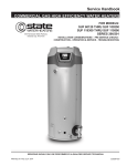
1
CITY OF MOORE BID NOTICE BID #1516-004 NOTICE IS HEREBY GIVEN that the City of Moore will receive sealed bids in the office of the City Clerk, Purchasing Division, Moore City Hall, 301 North Broadway, Suite 142, Moore, Oklahoma, 73160, for the PURCHASE OF A 100’ AERIAL LADDER FIRE TRUCK for the City of Moore Fire Department. Bids will not be accepted after 1:45 P.M., CST, MONDAY, NOVEMBER 30, 2015. Bids will be made in accordance with the specifications, and these specifications are on file and available for examination, or may be obtained from the office of the Purchasing Agent, Moore City Hall. One (1) copy addressed to the City of M oore P urchasing Agent will be submitted, and that copy must be sealed and clearly marked with the name of the bidding vendor and identified as follows: “SEALED BID #1516-004” “PURCHASE OF A 100’ AERIAL LADDER FIRE TRUCK” Bids filed as provided herein will be publicly opened at 2:00 p.m., CST, Monday, November 30, 2015, Moore City Hall, City Council Chambers, 301 North Broadway, Suite 126, Moore, Oklahoma 73160. All bids will remain at least forty-eight (48) hours thereafter, before a contract will be made and entered into thereon. Bids received more than ninety-six (96) hours [excluding Saturdays, Sundays and holidays], before the time set for the receipt of bids will not be considered. The City of Moore reserves the right to accept the bid which, in the judgment of the Staff, is the best for the application of needs, materials and services as covered in the specifications, and is deemed the best, overall, for the good of the City. The City of Moore reserves the right to reject any and all bids; waive irregularities and formalities in any bid submitted. In addition, the City of Moore reserves the right to contract with one or more parties to perform identical services as deemed appropriate. The City of Moore is an equal opportunity employer. Carol Folsom, Purchasing Agent 405/793-5022 CITY OF MOORE FIRE DEPARTMENT SPECIFICATIONS FOR 100’ AERIAL PLATFORM CONTACT INFORMATION Doug Scott, Assistant Fire Chief Moore Fire Department 2400 S. Fritts Blvd. Moore, OK 73160 (405) 793-5110 phone (405) 793-5127 fax [email protected] TABLE OF CONTENTS Table of Contents Certificate of Insurance ........................................................................................................... 1 Delivery................................................................................................................................... 1 Exceptions ............................................................................................................................... 1 Intent of Specifications ........................................................................................................... 2 ISO Compliance ...................................................................................................................... 3 Proposal Price ......................................................................................................................... 3 Service Certification ............................................................................................................... 3 Service & Support ................................................................................................................... 3 Single Source Manufacturing - Aerial .................................................................................... 4 Oklahoma Motor Vehicle License .......................................................................................... 4 Cab Crashworthiness Testing ................................................................................................. 4 NFPA Compliance .................................................................................................................. 4 Pre-build Conference .............................................................................................................. 4 Ladder Mount Inspection ........................................................................................................ 5 Final Inspection....................................................................................................................... 5 Bumper Tray - Center ............................................................................................................. 5 Lid, Bumper Hose Tray .......................................................................................................... 5 Bumper .................................................................................................................................... 5 Front Bumper Extension ......................................................................................................... 5 Bumper Gravel Shield............................................................................................................. 6 Frame Rail Construction ......................................................................................................... 6 Shock Absorbers Front ........................................................................................................... 6 Rear Axle ................................................................................................................................ 6 Front Axle ........................................................................................................................ 6 & 7 Rear Suspension ...................................................................................................................... 7 Front Wheel Trim Package ..................................................................................................... 7 Rear Wheel Trim Package, Tandem Axle .............................................................................. 7 Front Wheels ........................................................................................................................... 7 Rear Wheels ............................................................................................................................ 7 Front Tires ............................................................................................................................... 8 Rear Tires ................................................................................................................................ 8 Tire Pressure Indicators .......................................................................................................... 8 ii TABLE OF CONTENTS Automatic Tire Chains ............................................................................................................ 8 Front Brakes ............................................................................................................................ 8 Rear Brakes ............................................................................................................................. 9 Brake System .......................................................................................................................... 9 Wheel Chocks ......................................................................................................................... 9 Park Brake Release ............................................................................................................... 10 Electronic Stability Control .................................................................................................. 10 Air Dryer ............................................................................................................................... 10 Air Inlet ................................................................................................................................. 10 Air Lines ............................................................................................................................... 11 Air Horns .............................................................................................................................. 11 Transmission Selector ........................................................................................................... 11 Vehicle Speed ....................................................................................................................... 11 Engine/Transmission Package .............................................................................................. 11 Engine .......................................................................................................................... 11 & 12 Transmission ................................................................................................................ 12 & 13 Jacobs Engine Brake ............................................................................................................. 13 Transmission Programming .................................................................................................. 13 Engine Cooling Package ....................................................................................................... 13 Radiator ................................................................................................................................. 13 Charge Air Cooler System .................................................................................................... 13 Charge Air Cooler Hoses ...................................................................................................... 14 Fan/Shroud ............................................................................................................................ 14 Transmission Cooler ............................................................................................................. 14 Fuel System ........................................................................................................................... 14 Dual Fuel Fill ........................................................................................................................ 14 Fuel Shut-Off ........................................................................................................................ 14 Fuel Line ............................................................................................................................... 15 360 Amp Alternator .............................................................................................................. 15 Battery System ...................................................................................................................... 15 Drivelines .............................................................................................................................. 15 Front Tow Eyes ..................................................................................................................... 15 Rear Tow Eyes ...................................................................................................................... 16 Power Take-Off .................................................................................................................... 16 DEF Tank .............................................................................................................................. 16 iii TABLE OF CONTENTS Power Steering Cooler .......................................................................................................... 16 Long Cab ............................................................................................................................... 16 Cab Exterior .......................................................................................................................... 17 Windshield Wipers................................................................................................................ 17 Cab Mount and Cab Tilt System .................................................................................. 17 & 18 Cab Interior ........................................................................................................................... 18 Barrier Style Cab Doors ........................................................................................................ 19 Interior Lighting .................................................................................................................... 19 Cab Instruments and Controls ...................................................................................... 19 & 20 Electrical System…………………………………………………………………………...20 Cab Crashworthiness Requirement ....................................................................................... 21 ISO Compliance .................................................................................................................... 21 Cab Roof Notch .................................................................................................................... 21 Logo Package ........................................................................................................................ 21 Cab Grille .............................................................................................................................. 21 Rear Cab Door Position ........................................................................................................ 22 Cab Door Panels ................................................................................................................... 22 Cab Door Reflective Material ............................................................................................... 22 Cab Door Locks .................................................................................................................... 22 Cab Front Door Windows ..................................................................................................... 22 Rear Cab Door Windows ...................................................................................................... 22 Mirrors, Heated ..................................................................................................................... 23 Cab Mirrors ........................................................................................................................... 23 Cab Windows Rear Wall ...................................................................................................... 23 Cab Canopy Window ............................................................................................................ 23 Front Mud Flaps .................................................................................................................... 23 Handrails ............................................................................................................................... 23 Air Conditioning ................................................................................................................... 24 Seating................................................................................................................................... 24 Seat, Driver ........................................................................................................................... 24 Seat, Officer .......................................................................................................................... 24 Seat, Rear Facing (Driver Side) ............................................................................................ 25 Seat, Rear Facing (Officer Side) ........................................................................................... 25 Seat Fabric Color .................................................................................................................. 25 Seating Capacity Tag ............................................................................................................ 25 iv TABLE OF CONTENTS Seat, Rear Wall ..................................................................................................................... 26 SCBA Bracket ....................................................................................................................... 26 Seat Cover Material .............................................................................................................. 26 Map Box................................................................................................................................ 26 Map Box Finish..................................................................................................................... 27 Cab Interior Color ................................................................................................................. 27 Sun Visors ............................................................................................................................. 27 Air Horn Lanyard .................................................................................................................. 27 Cab Dash - Severe Duty........................................................................................................ 27 Cab Dome Lights .................................................................................................................. 27 DPF Regeneration Override.................................................................................................. 28 English Dominant Gauge Cluster ......................................................................................... 28 Headlights ............................................................................................................................. 28 Cab 12 Volt Outlet ................................................................................................................ 28 Battery Charger ..................................................................................................................... 29 Battery Charger Receptacle .................................................................................................. 29 Receptacle Mounting Plate ................................................................................................... 29 Cab Turn Signals................................................................................................................... 29 Interior Lighting .................................................................................................................... 29 Steering Wheel Switches (if available) ................................................................................. 30 Aerial Equipment Body ........................................................................................................ 30 Body Mainframe ................................................................................................................... 30 Body Side Assemblies .......................................................................................................... 30 Stablizer Openings ................................................................................................................ 31 Body Mounting System ........................................................................................................ 31 Rear Body Design ................................................................................................................. 31 Side Aerial Access Staircase ................................................................................................. 31 Water Tank Mounting System .............................................................................................. 31 Compartments ....................................................................................................................... 32 Driver Side Compartments ................................................................................................... 32 Officer Side Compartments .................................................................................................. 32 Compartment Doors .............................................................................................................. 32 Adjustable Shelf .................................................................................................................... 32 Roll-out Tray......................................................................................................................... 33 Tool Boards and Slide Outs .................................................................................................. 33 v TABLE OF CONTENTS Handrails ............................................................................................................................... 33 Steps, Standing, and Walking Surfaces ................................................................................ 33 Apparatus Warning Labels ................................................................................................... 34 Rubrail................................................................................................................................... 34 Pump Compartment .............................................................................................................. 34 Rear Body Platework ............................................................................................................ 34 Triple Crosslay Hosebeds ..................................................................................................... 34 Backboard Storage Compartment ......................................................................................... 35 Dunnage Pan ......................................................................................................................... 35 Auxiliary Ground Pads ......................................................................................................... 35 Hosebed................................................................................................................................. 35 Rear Hosebed Cover ............................................................................................................. 35 Vinyl Crosslay Cover ............................................................................................................ 36 Pump Panels .......................................................................................................................... 36 Hinged Gauge Panel ............................................................................................................. 36 Pump Access Door ................................................................................................................ 36 Pump Panel Tags................................................................................................................... 36 Mechanically Fastened Tags ................................................................................................. 37 Air Horn Switch .................................................................................................................... 37 Booster Tank ................................................................................................................ 37 & 38 Tank Fill 2 Akron Valve ....................................................................................................... 38 Tank to Pump, 3" Akron Valve ............................................................................................ 38 20 Gallon Foam Tank ........................................................................................................... 39 Rear Pike Pole Storage.......................................................................................................... 39 Rear Control Doors ............................................................................................................... 39 Rear Ladder Storage ............................................................................................................. 40 Ladder Tunnel Door .............................................................................................................. 40 Right Side Pump Panel Step Package ................................................................................... 40 Folding Step .......................................................................................................................... 40 Rear Mud Flaps ..................................................................................................................... 40 Overall Height Restriction .................................................................................................... 40 Overall Length Restriction.................................................................................................... 41 Side Body Platework............................................................................................................. 41 Body Wheel Well .................................................................................................................. 41 SCBA Wheel Well Bottle Storage ........................................................................................ 41 vi TABLE OF CONTENTS Fire Pump System ................................................................................................................. 42 Discharge Manifold .............................................................................................................. 42 Priming System ..................................................................................................................... 42 Pump Shift ............................................................................................................................ 43 Systems ................................................................................................................................. 43 Gearbox Cooler ..................................................................................................................... 43 Auxiliary Engine Cooler ....................................................................................................... 43 Pump Rating.......................................................................................................................... 44 Pump Certification ................................................................................................................ 44 Speed Counter ....................................................................................................................... 44 Steamers, Flush+1 ................................................................................................................. 44 Thermal Relief Valve ............................................................................................................ 44 Mechanical Pump Seal .......................................................................................................... 45 Manual Master Drain ............................................................................................................ 45 Anodes Pro System ............................................................................................................... 45 Pump Cooler ......................................................................................................................... 45 Left & Right Intake 2.5 Akron Valves.................................................................................. 46 Intake Relief Valve ............................................................................................................... 46 Front Jump Line 1.5 Akron Valve ............................................................................... 46 & 47 Swivel Elbow ........................................................................................................................ 47 1.5 Single Crosslay Akron Valve [Qty: 2] ............................................................................ 47 Single Crosslay 2.5 Akron Valve................................................................................. 47 & 48 Discharge Left Panel 2.5 Akron Droop ................................................................................ 48 Discharge Right Panel 2.5 Akron Droop ..................................................................... 48 & 49 Right 4 Discharge w/9323 Controller ................................................................................... 49 Discharge Waterway 4 .......................................................................................................... 49 IC Push/Pull Control ............................................................................................................. 50 Bleeder Drain Valve [Qty: 9] ................................................................................................ 50 Discharge/Intake Bezel ......................................................................................................... 50 Pump Pressure Governor ............................................................................................. 50 & 51 LED Foam Gauge Requirement............................................................................................ 51 LED Water Tank Level ......................................................................................................... 51 Engine Gauge Package ......................................................................................................... 51 2.5 Discharge Gauges [Qty: 9]..................................................................................... 51 & 52 4" Master Pressure Gauges w/Bezel ..................................................................................... 52 vii TABLE OF CONTENTS Foam System ......................................................................................................................... 52 Foam System Plumbing ........................................................................................................ 53 Multiplex Modem ................................................................................................................. 53 Multiplex Electrical System .................................................................................................. 53 Electrical System .................................................................................................................. 53 Multiplex System .................................................................................................................. 54 Wiring ................................................................................................................................... 54 Wiring Protection .................................................................................................................. 55 Wiring Connectors ................................................................................................................ 55 NFPA Required Testing of Electrical System ...................................................................... 55 NFPA Required Documemtation .......................................................................................... 55 Vehicle Data Recorder .......................................................................................................... 56 Occupant Detetion System .................................................................................................... 56 HVAC Controls .................................................................................................................... 56 Multiplex Display ................................................................................................................. 57 Light Bars.............................................................................................................................. 57 Lower Level Warning Light Package ................................................................................... 57 Upper Rear Warning Lights .................................................................................................. 57 Hazard (Door Ajar) Light ..................................................................................................... 57 Warning Lights ..................................................................................................................... 58 Electronic Siren ..................................................................................................................... 58 Electronic Siren Control Location ........................................................................................ 58 Siren Speaker ........................................................................................................................ 58 License Plate Light ............................................................................................................... 58 LED Marker Lights ............................................................................................................... 58 Tail Lights ............................................................................................................................. 59 Compartment Light Package................................................................................................. 59 Step Lights ............................................................................................................................ 59 Ground Lights ....................................................................................................................... 59 Cab Scene Light Switching................................................................................................... 60 Deck Lights ........................................................................................................................... 60 Deck/Scene Light Wired to Back-Up Lights ........................................................................ 60 Scene Lights .......................................................................................................................... 60 Crosslay Light ....................................................................................................................... 60 Scene Light ........................................................................................................................... 61 viii TABLE OF CONTENTS Engine Compartment Light................................................................................................... 61 Pump Compartment LED Light ............................................................................................ 61 LED Pump Panel Light Package........................................................................................... 61 Camera Back-Up .......................................................................................................... 61 & 62 Two-Way Intercom ............................................................................................................... 62 Back-Up Alarm ..................................................................................................................... 62 12 Volt DC Power Distribution Module ............................................................................... 62 6KW Hydraulic Generator .................................................................................................... 63 Ratings and Capacity ............................................................................................................ 63 3rd Party Generator Testing .................................................................................................. 63 Generator Air Deflector ........................................................................................................ 64 Circuit Breaker Panel ............................................................................................................ 64 Whelen Pioneer 120V LED Flood Lights ............................................................................. 64 Receptacles ........................................................................................................................... 64 Electric Cord Reel ................................................................................................................. 65 Cord Reel Rollers .................................................................................................................. 65 Cord Reel Rewind Switch..................................................................................................... 65 100 Ft. Rear Mount Elevating Platform ................................................................................ 65 Elevating Platform Requirements ......................................................................................... 65 Aluminum Elevating Platform .............................................................................................. 66 Firefighting Platform ............................................................................................................ 67 Harness Attachments ............................................................................................................ 67 Platform Water Curtain ......................................................................................................... 67 Platform Leveling System..................................................................................................... 67 Platform Lifting Eyes ............................................................................................................ 67 Aerial Finish.......................................................................................................................... 68 Ladder Extension Mechanism............................................................................................... 68 Ladder Slide System ............................................................................................................. 68 Aerial Extension Indicator .................................................................................................... 68 Elevating Platform Operating Positions................................................................................ 68 Aerial Ladder Control Levers ............................................................................................... 69 Variable Speed Control System ............................................................................................ 69 Body Protection System ........................................................................................................ 69 Load Indication System ........................................................................................................ 70 Operation Times.................................................................................................................... 70 ix TABLE OF CONTENTS Elevating Platform Rated Capacity ....................................................................................... 70 Hydraulic System .................................................................................................................. 71 Aerial Torque Box ................................................................................................................ 72 Stablization ........................................................................................................................... 72 Stablizer Controls.................................................................................................................. 72 Forward Aerial Support ........................................................................................................ 72 Turntable Support Assembly ................................................................................................ 72 Upper Turntable .................................................................................................................... 73 Elevation Mechanism ........................................................................................................... 73 Rotation Mechanism ............................................................................................................. 73 Aerial Electric Power ............................................................................................................ 73 Elevating Platform Water Delivery System .......................................................................... 73 Waterway Relief Valve ......................................................................................................... 74 ISO Compliance .................................................................................................................... 74 Aerial Raise ........................................................................................................................... 74 Aerial Hydraulic Oil Level Gauge ........................................................................................ 74 Extended Outrigger Feet ....................................................................................................... 74 Platform Pivot Control .......................................................................................................... 74 Platform Console Cover........................................................................................................ 75 1250 GPM Electric Monitor ................................................................................................. 75 Monitor Finish ...................................................................................................................... 75 Monitor Tip Controls ............................................................................................................ 75 Platform Monitor Valve ........................................................................................................ 75 LED Outrigger Lights (4) ..................................................................................................... 76 Warning Lights on Front of Platform ................................................................................... 76 Warning Lights on Sides of Platform ................................................................................... 76 Ladder Base Lighting ............................................................................................................ 76 Quartz Light .......................................................................................................................... 76 Ladder Climbing Lights ........................................................................................................ 77 LED Flood Light ................................................................................................................... 77 Platform Preconnect .............................................................................................................. 77 Waterway Inlet ...................................................................................................................... 77 Reducing Elbow for Aerial Discharge .................................................................................. 78 Waterway Pressure Gauge .................................................................................................... 78 Aerial Tip Receptacle ........................................................................................................... 78 x TABLE OF CONTENTS Aerial Information System ........................................................................................... 78 & 79 Audible Warnings ................................................................................................................. 79 Visual Warnings.................................................................................................................... 79 Display Screens ..................................................................................................................... 79 Electronic Control Modules .................................................................................................. 80 Sensors .................................................................................................................................. 80 Wiring Harness ..................................................................................................................... 80 Durability .............................................................................................................................. 81 Diagnostics ............................................................................................................................ 81 Aerial Breathing Air System ................................................................................................. 81 Axe Bracket .......................................................................................................................... 82 Pike Pole Mount.................................................................................................................... 82 Lifting Eye / Tie-off Package ............................................................................................... 82 Hose Box ............................................................................................................................... 82 Stokes Basket Receiver ......................................................................................................... 82 Rappelling Rope Guides ....................................................................................................... 83 Roof Ladder Bracket ............................................................................................................. 83 Parapet Roof Ladder Bracket ................................................................................................ 83 Aerial Sign Plate ................................................................................................................... 83 Third-Party Flow Test ........................................................................................................... 83 Aerial Certification ...................................................................................................... 84 & 85 Alco-Lite 14’ Roof Ladder ................................................................................................... 85 Alco-Lite 18’ Roof Ladder ................................................................................................... 85 Alco-Lite 24’ Extension Ladder ........................................................................................... 85 Alco-Lite 30’ Extension Ladders .......................................................................................... 86 Alco-Lite 12’ Roof Ladder ................................................................................................... 86 10’ Folding Ladder ............................................................................................................... 86 DOT Required Drive Away Kit ............................................................................................ 86 Paint Break ............................................................................................................................ 86 Painted Pump/Pre-Connect Module(s) ................................................................................. 86 Paint Custom Cab ................................................................................................................. 87 Paint Cab Two-Tone Color ................................................................................................... 87 Paint Body Large .................................................................................................................. 87 Aerial Paint ........................................................................................................................... 87 Cab Interior Paint .................................................................................................................. 87 xi TABLE OF CONTENTS Reflective Tape on Jacks ...................................................................................................... 87 Striping & Lettering .............................................................................................................. 88 Rear Body 3M Diamond Grade Striping .............................................................................. 88 Standard 1 Year Warranty .................................................................................................... 88 Lifetime Frame Warranty ..................................................................................................... 88 10 Year 100,000 Mile Structural Warranty .......................................................................... 88 10 Year Stainless Steel Plumbing Warranty ......................................................................... 89 20 Year Aerial Device Structural Warranty.......................................................................... 89 10 Year Paint and Corrosion Warranty................................................................................. 89 Training ................................................................................................................................. 90 Approval Drawings ............................................................................................................... 90 Electronic Manuals ...................................................................................................... 90 & 91 Manuals Printed Set .............................................................................................................. 91 Fire Apparatus Safety Guide................................................................................................. 91 1Ok Contingency Fund ......................................................................................................... 91 Finance Options .................................................................................................................... 92 xii Certificate of Insurance Each bidder shall furnish, with their proposal, a Certificate of Product Liability Insurance for a minimum of twenty five (25) million dollars. Failure to provide this documentation shall render the proposal non-responsive and the bid shall be rejected. This certificate shall be from the prime builder only. Certificates submitted from various sub-contractors in order to total the twenty five (25) million dollar minimum will not be acceptable as meeting the requirements of this section. If one of the major portions of the apparatus (i.e. chassis, aerial, or body) is not designed, fabricated, and assembled by the prime builder, a separate Certificate of Liability Insurance for a minimum of twenty five (25) million dollars must be provided by each additional contractor. The Certificate must be made out to the Purchaser and must be original. Submission of a nonoriginal Certificate or providing a Certificate that is not made out to the Purchaser will not meet the requirements of this section. Yes Complies No Delivery The bidder shall state the time required for delivery of the completed unit on the proposal page. The completed unit shall be delivered to the purchaser under its own power. Rail or truck delivery will not be acceptable. Full instructions shall be provided to three (3) Fire Department shifts on operation, care and maintenance of apparatus at the purchaser's location. All training shall be conducted by a certified factory trainer. Yes Complies No Exceptions The following apparatus specifications are considered minimum design and construction standards against which the apparatus will be inspected. It is the intent to receive proposals on equipment/apparatus meeting the attached detailed specifications in their entirety. Any proposals being submitted without ''Full Compliance'' with these specifications shall so state on the bid proposal page, followed by a detailed ''Letter of Exceptions'' listing the areas of noncompliance. The reference must include page number, paragraph, and the exact nature of the exception. Failure to follow this format, provided for the convenience of the Purchaser, will render the vendor's proposal non-responsive and ineligible for award of contract. The Purchaser may add the statement ''No Exception'' to a component or design feature in these specifications. In the interest of fleet conformity or specific performance requirements, the Purchaser will not permit exceptions taken to these item(s). The Purchaser reserves the right to reject any or all bid proposals and purchase the equipment it deems most suitable to its needs. The Purchaser does not, in any way, obligate itself to accept the lowest or any bid. Any bidder taking total exception to the complete specification or a major element will result in immediate rejection of the proposal. Any exceptions accepted or denied, will be at the sole discretion of the City of Moore or its agent. Yes Complies No 1 Intent of Specifications It is the intent of these specifications to clearly describe the furnishing and delivery to the Purchaser, a complete apparatus equipped as specified. The primary objective of these specifications is to obtain the most acceptable apparatus for service in the Moore Fire Department. These specifications cover specific requirements as to the type of construction and tests the apparatus must conform, together with certain details as to finish, material preferences, equipment and appliances with which the successful bidder must conform. The design of the apparatus must embody the latest approved automotive design practices. The workmanship must be of the highest quality in its respective field. Special consideration shall be given to service access to areas needing periodic maintenance, ease of operation, and symmetrical proportions. Construction must be heavy-duty and ample safety factors must be provided to carry loads as specified. The construction method employed will be in such a manner as to allow ready removal of any component for service or repair. The apparatus shall conform to the National Fire Protection Association Standard for Automotive Fire Apparatus, 1901, in its most recent edition, unless otherwise specified in this document. Only the specified firefighting support equipment listed in these specifications shall be provided. The apparatus shall further conform to all Federal Motor Vehicle Safety Standards. No exception. Each bidder shall furnish satisfactory evidence of their ability to design, engineer, and construct the apparatus specified and shall state the location of the factory producing the apparatus. They shall also substantiate they are in a position to render prompt and proper service and to furnish replacement parts for the apparatus. Each bid must be accompanied by a set of detailed contractor's specifications consisting of a detailed description of the apparatus and equipment proposed. All bid proposal specifications must be in the same sequence as the advertised specification for ease of comparison. These specifications shall include size, location, type, and model of all component parts being furnished. Detailed information shall be provided on the materials used to construct all facets of the apparatus body. Any bidder who fails to submit detailed construction specifications, or who photo copies and submits these specifications as their own construction details will be considered non-responsive and shall render their proposal ineligible for award. No exception. Bids will be addressed and submitted in accordance with the instructions provided on the cover sheet. The words ''Fire Apparatus Proposal'', the date, and bid opening time shall be stated on the front of the bid envelope. It shall be the responsibility of the bidder to assure that their proposal arrives at the location and time indicated. Late proposals, telegrams, facsimile, or telephone bids will not be considered. No exception. All bidders are required to detail the payment terms for apparatus on the bidder's proposal page. Any required prepayments or progress payments must be explained in detail. Yes Complies No 2 ISO Compliance • The manufacturer shall operate a Quality Management System meeting the requirements of ISO 9001. • If the manufacturer operates more than one manufacturing facility each facility must be ISO certified. • By virtue of its ISO compliance the manufacturer shall provide an apparatus that is built to exacting standards, meets the customer’s expectations, and satisfies the customer’s requirements. • A copy of the manufacturer’s certificate of ISO compliance for each manufacturing facility shall be provided with the bid. Yes Complies No Proposal Price Each bidder's proposal must include all items required in the specifications unless a specific exception is taken. Any bidder who option prices an item included in these specifications that does not specifically require option pricing will have their proposal rejected without further cause. Yes Complies No Service Certification Each bidder shall supply with their bid an Emergency Vehicle Technician certification, and photos of the full service repair facility that is located within the State of Oklahoma, these documents must be provided with the proposal. Yes Complies No Service & Support To insure full service after delivery, the bidder must be capable of providing service when required. The bidder shall show that the company is in position to render prompt service and furnish replacement parts. Each bidder must be able to display that they are actively in the fire apparatus service business by operating an authorized service center located within the State of Oklahoma. Detailed information shall be provided on service facilities, personnel, service vehicles, and how long the service facility has operated in the State of Oklahoma. Service is a criterion for award of this bid. Yes Complies No 3 Single Source Manufacturing - Aerial In order to protect the Purchaser from divided warranty responsibility between chassis, aerial, and body manufacturers, proposals will only be considered from apparatus builders who design, fabricate, and assemble the complete apparatus at their own facilities. This shall include the cab shell, chassis assembly, aerial device, and complete body structure. Private labeling of another manufacturer's chassis, aerial, or body will not meet the requirements of this section. Yes Complies No Oklahoma Motor Vehicle License Each manufacturer and dealer must furnish a copy of their Oklahoma Motor Vehicle Commission License. Yes Complies No Cab Crashworthiness Testing All bidders must submit documentation of cab worthiness testing from a certified third party testing facility. The crashworthiness must meet the standards for dynamic roof pre-load, static roof load and dynamic frontal impart tests as defined by ECE R29, SAE J2422 and SAE J2420. Safety is paramount to the fire fighters; this document is required to be supplied with the bid proposal. Failure to provide this document will render the bid incomplete and disqualify the bidder from the bid process. Yes Complies No NFPA Compliance The supplied components of the apparatus shall be compliant with NFPA 1901, 2009 edition. Yes Complies No Pre-build Conference A pre-build conference will be held at the manufactures facility. Three (3) members of the Moore Fire Department will be accompanied by a dealer representative. Do to the size and complexity of this truck, two (2) full conference days shall be scheduled. All expenses including air fare, meals, lodging and any other related expenses will be covered by the manufacturer or dealer. Yes Complies No 4 Ladder Mount Inspection A ladder mount inspection shall be required at the manufacturer’s facility. Two (2) members of the Moore Fire Department will be accompanied by a dealer representative. All expenses including air fare, meals, lodging and any other related expenses will be covered by the manufacturer or dealer. Yes Complies No Final Inspection A final inspection will be required before the completed truck leaves the manufacturers facility. Three (3) members of the Moore Fire Department will be accompanied by a dealer representative. Do to the size and complexity of this truck, two (2) full inspection days will be required. All expenses including air fare, meals, lodging and any other related expenses will be covered by the manufacturer or dealer. Yes Complies No Bumper Tray - Center A hose tray constructed of 1/8” aluminum shall be recessed into the front bumper extension. The tray shall be located in the center of the bumper and be approximately 12" deep (11" to the top of the slats). One inch thick aluminum slats shall be included in the bottom of the hose tray to aid in the dissipation of water from the tray. Yes Complies No Lid, Bumper Hose Tray The center bumper tray shall have a diamond plate lid. The lid shall be hinged and shall be secured in the closed position by a D-Ring latch and held open with a pneumatic shock. Yes Complies No Bumper A heavy duty 10" high polished stainless steel type front bumper shall be provided. A channel shall be mounted directly behind the bumper for additional strength. Yes Complies No Front Bumper Extension The bumper shall be extended approximately 20” from the face of the cab as required. Yes Complies No 5 Bumper Gravel Shield The extended front bumper gravel shield shall be made of aluminum treadplate material. Yes Complies No Frame Rail Construction The chassis frame shall be designed, engineered and manufactured to meet or exceed current industry standards. The entire assembly shall be sand blasted and painted black before chassis assembly. A full lifetime warranty against defects in materials or workmanship shall be supplied by the apparatus manufacturer. The custom chassis frame shall have a WHEEL ALIGNMENT in order to achieve maximum vehicle road performance and to promote long tire life. The alignment shall conform to current industry standards. All wheel lug nuts and axle U-bolt retainer nuts shall be tightened to the proper torque at the time of alignment. The wheel alignment documentation shall be made available at delivery upon request. Yes Complies No Shock Absorbers Front Koni model 90 or equivalent, shock absorbers shall be provided for the front axle. The shocks shall be covered by the manufacturer`s standard warranty. Yes Complies No Rear Axle The vehicle shall utilize an ArvinMeritor rear tandem axle that is of appropriate size and weight for the vehicle. A 2-year/unlimited miles parts and 2-year labor rear axle warranty shall be provided as standard by ArvinMeritor Automotive. Yes Complies No Front Axle The vehicle shall utilize a drop beam front axle with the appropriate rated capacity for the vehicle. The vehicle shall have a nominal cramp angle of 45 degrees including front suction applications. The front axle hubs shall be made from ductile iron and shall be designed for use with 10-hole hub-piloted wheels in order to improve wheel centering and extend tire life. 6 The vehicle shall be equipped with a Sheppard integral model M-110 power steering gear, or equivalent, used in conjunction with a power assist cylinder. The steering assembly shall be rated to statically steer up to a maximum front axle load of 24,000 lbs. Relief stops shall be provided to reduce system pressure upon full wheel cut. The system shall operate mechanically should the hydraulic system fail. A 2 year/unlimited miles, parts and 2 year labor axle warranty shall be provided as standard by Dana. Yes Complies No Rear Suspension The rear suspension shall be designed, engineered and built to current industry standards. The suspension shall be rated for the maximum axle capacity. Yes Complies No Front Wheel Trim Package The front wheels shall have stainless steel lug nut covers and stainless steel hub covers. Yes Complies No Rear Wheel Trim Package, Tandem Axle The rear wheels shall have stainless steel lug nut covers and stainless steel high hats. Yes Complies No Front Wheels The vehicle shall have two (2) Accuride polished (on outer wheel surfaces only) aluminum disc wheels. They shall be forged from one-piece corrosion-resistant aluminum alloy and sized appropriately for the tires. Yes Complies No Rear Wheels The vehicle shall have eight (8) Accuride polished (on outer wheel surfaces only) aluminum disc wheels. They shall be forged from one-piece corrosion-resistant aluminum alloy and sized appropriately for the tires. Yes Complies No 7 Front Tires • • • The front tires shall be 425/65R22.5 tubeless type 20 PR radial tires with highway tread. The wheels and tires shall conform to the Tire and Rim Association requirements. The tires with wheels shall have the following weight capacity and speed rating: o Max front rating with Alco aluminum wheels - 24,400 @ 65 MPH (intermittent fire service rating if GAW is over 22,800) Yes Complies No Rear Tires • • • The rear tires shall be 315/ 22.5 tubeless type radial tires with mud and snow tread. The wheels and tires shall conform to the Tire and Rim Association requirements. The tires with wheels shall have the following weight capacity: o 66,160 lbs. (dual) @ 75 MPH. Yes Complies No Tire Pressure Indicators The apparatus shall be provided with LED tire pressure indicating valve stem caps. When the tire is under inflated by 5-10 PSI, the LED indicator on the cap shall flash red. The indicator housings shall be shock resistant and constructed from polished stainless steel. The indicators shall be calibrated by attaching to valve stem of a tire at proper air pressure per load ratings and easily re-calibrated by simply removing and re-installing them during service. Yes Complies No Automatic Tire Chains Automatic tire chains shall be installed to current industry standards. The chain system shall be Insta Chain, On Spot, or Rudd brand. Yes Complies No Front Brakes • • • The front axle shall be equipped with Dana ESD225 17 inch disc brakes. A 3 year/unlimited miles parts and 3 year labor brake warranty shall be provided as standard by Dana. The warranty shall include bushings and seals. Yes Complies No 8 Rear Brakes • • • The rear axle shall be equipped with ArvinMeritor 16-1/2” x 7” S-cam brakes with cast brake drums. Q-Plus shoes shall be provided with up to 48,000 lb. axle ratings and P-Type shoes with over 48,000 lb. axle ratings. The rear axle brakes shall be furnished with automatic slack adjusters. o A 3 year/unlimited miles parts and 3 year labor rear brake warranty shall be provided as standard by ArvinMeritor Automotive. o The warranty shall include bushings, seals, and cams. Yes Complies No Brake System The vehicle shall be equipped with air operated brake system. The system shall meet or exceed the design and performance requirements of current FMVSS-121 and test requirements of current NFPA 1901 Standard. An automatic drain valve shall be installed on the wet tank. All other tanks shall be equipped with manual drain valves. A Wabco ABS or equivalent, system shall be provided to improve vehicle stability and control by reducing wheel lock-up during braking. This braking system shall be fitted to axles and all electrical connections shall be environmentally sealed. The system shall constantly monitor wheel behavior during braking. A warning light at the driver`s instrument panel shall indicate malfunction to the operator. The system shall also interface with the application of the auxiliary engine brake to prevent wheel lock. To improve service trouble-shooting, provisions in the system for an optional diagnostic tester shall be provided. The system shall test itself each time the vehicle is started and a dashmounted light shall go out once the vehicle is moving above 4 MPH. A 3 year/300,000 mile parts and labor Anti-Locking Braking System (ABS) warranty shall be provided as standard by Meritor Automotive. Yes Complies No Wheel Chocks There shall be one (1) pair of folding aluminum alloy wheel chocks with easy grip handles and brackets provided. Yes Complies No 9 Park Brake Release One (1) Bendix-Westinghouse PP-5 parking brake control valve shall be supplied within easy reach of the driver. Yes Complies No Electronic Stability Control The apparatus shall be equipped with an Electronic Stability Control (ESC) system that combines the functions of Roll Stability Control (RSC) with the added capability of yaw or rotational sensing. Intervention by the system occurs in three forms - engine, retarder and brake control. The ESC system uses several sensors to monitor the vehicle. These include a steering wheel angle sensor, lateral accelerometer, and yaw position sensor. ESC constantly monitors driving conditions and intervenes if critical lateral acceleration is detected or if the vehicle begins to spin due to low friction surfaces. The system provides control of engine and retarder torque as well as automatically controlling individual wheels to counteract both over steer and under steer. To further improve vehicle drive characteristics, the unit shall be fitted with Automatic Traction Control (ATC). This system shall control drive wheel slip during acceleration from a resting point. An extra solenoid valve shall be added to the ABS system. The system shall control the engine and brakes to improve acceleration slip resistance. The system shall have a dash mounted light that shall come on when ATC is controlling drive wheel slip. The ATC shall be equipped with a dash mounted override switch. 3 year/300,000 miles parts and labor warranties for ESC, RSC, and ATC shall be provided as standard by Meritor Automotive. Yes Complies No Air Dryer The chassis air system shall be equipped with a Bendix-Westinghouse AD-9 air dryer to remove moisture from the air in order to help prevent the air lines from freezing in cold weather and prolong the life of the braking system components. Yes Complies No Air Inlet A 1/4” brass quick-release air inlet with a male connection shall be provided. The inlet shall allow a shoreline air hose to be connected to the vehicle, discharging air directly into the wet tank of the air brake system. It shall be located driver door jamb. Yes Complies No 10 Air Lines Air brake lines shall be constructed of color coded nylon tubing routed in a manner to protect them from damage. Brass fittings shall be provided. Yes Complies No Air Horns Dual air horns shall be provided connected to the chassis air system. The horns shall be mounted through the front bumper. The front bumper shall have two (2) holes punched to accommodate the air horns. A pressure protection valve shall be installed to prevent the air brake system from being depleted of air pressure. Yes Complies No Transmission Selector A push-button transmission shift module, Allison model 29538373, shall be located to the right side of the steering column within easy reach of the driver. The shift position indicator shall be indirectly lit for after dark operation. The shift module shall have a “Do Not Shift” light and a “Service” indicator light. The shift module shall have means to enter a diagnostic mode and display diagnostic data including oil life monitor, filter life monitor, transmission health monitor and fluid level. A transmission temperature gauge with warning light and buzzer shall be installed on the cab instrument panel. Yes Complies No Vehicle Speed Electronic speed limiting set at 60 MPH as required by NFPA 1901. Yes Complies No Engine/Transmission Package Engine The vehicle shall utilize a Cummins ISX12 engine as described below: • • • • • • • • 500 Horsepower Six (6) cylinder Variable Geometry Turbocharged Charge Air Cooled (CAC) 4-cycle diesel Cummins XPI high pressure fuel injection system Fuel cooler (when equipped with a fire pump) 729 cu. in. displacement 500 gross BHP at 1800 RPM and a peak torque of 1645 lb. ft. at 1200 RPM with a governed RPM of 2100 11 • Bore and stroke shall be 5.11 x 5.91 • Compression ratio shall be 17:1 • Engine lubrication system shall have a minimum capacity, to include filter, of 43 quarts • Cooled Exhaust Gas Recirculation (EGR) • Delco-Remy 39 MD-HD 12 volt starter • Interacta System • Coolant filter with shut-off and corrosion inhibiting additive • 18.7 cubic foot per minute air compressor • After treatment system consisting of a oxidation catalyst and diesel particulate filter and selective catalyst reduction system • Ember separator compliant with 2009 NFPA 1901 standard • The engine shall be compliant with 2013 EPA Emission standards The engine air intake shall be to current industry standards. The engine exhaust piping shall be a minimum of 4” diameter welded aluminized steel tubing. The muffler shall be mounted horizontally under the right-hand frame rail in back of the cab in order to minimize heat transmission to the cab and its occupants. The exhaust shall be directed away from the vehicle on the right side ahead of the rear wheels in order to keep exhaust fumes as far away as possible from the cab and pump operator position. A 5-year/100,000 miles parts and labor warranty will be provided as standard by Cummins. A copy of the Engine Installation Review stating the engine installation meets Cummins recommendations shall be provided as requested. The engine installation shall not require the operation of any type of “power-down” feature to meet engine installation tests. Yes Complies No Transmission The vehicle shall utilize an Allison EVS4000P, electronic, 5-speed automatic transmission. A transmission oil temperature gauge with warning light and buzzer shall be installed on the cab instrument panel to warn the driver of high oil temperatures that may damage the transmission. The transmission shall have a gross input torque rating of 1675 lb. ft. and a gross input power rating of 580 HP. The gear ratios shall be as follows: 1 - 3.51 2 - 1.91 3 - 1.43 4 - 1.00 5 - .74 R - 4.80 The transmission shall be equipped with a fluid level sensor (FLS) system, providing direct feedback of transmission oil level information to the operator. The transmission shall have a lubricant capacity of 51 quarts. A water-to-oil transmission oil cooler shall be provided to ensure proper cooling of the transmission when the vehicle is stationary (no air flow). The transmission shall contain two engine driven PTO openings located at the 1 and 8 o`clock positions. The automatic transmission shall be equipped with a power lock-up device. The transmission lock-up shall prevent down shifting of transmission when engine speed is decreased during pump operations, thereby maintaining a constant gear ratio. Transmission 12 lock-up shall be automatically activated when placing pump in gear. Transmission lock-up shall be automatically deactivated when disengaging pump for normal road operation. A 5-year/unlimited miles parts and labor warranty shall be provided as standard by Allison Transmission. Yes Complies No Jacobs Engine Brake One (1) Jacobs engine brake shall be installed to assist in slowing and controlling the vehicle as required by NFPA 1901 for vehicles with gross vehicle weight ratings (GVWR) of 36,000 lbs. or greater. An on-off control switch and a high-medium-low selector switch shall be mounted in the cab accessible to the driver. When activated, the Jacobs engine brake shall cut off the flow of fuel to the cylinders and alter the timing of the exhaust valves. This shall transform the engine into a high-pressure air compressor, driven by the wheels, and the horsepower absorbed by the engine in this mode shall slow the vehicle. The selector switch allows the driver to select the amount of retarding power. When the on-off switch is in the “on” position, the engine brake shall be automatically applied whenever the accelerator is in the idle position and the automatic transmission is in the lock-up mode. If the accelerator is depressed or if the on-off switch is placed in the “off” position, the engine brake shall immediately release and allow the engine to return to its normal function. Yes Complies No Transmission Programming The transmission shall include the Allison 2nd gear Pre-Select feature. This option will direct the transmission to down shift to second gear when the throttle is released and the Jacobs engine brake is engaged. This feature is designed to increase brake life and aid vehicle braking. Yes Complies No Engine Cooling Package See below for information Radiator The cooling system shall be engineered, built and installed to current industry standards. Yes Complies No Charge Air Cooler System The system shall include a charge air cooler to ensure adequate cooling of the turbocharged air for proper engine operation and maximum performance. Yes Complies No 13 Charge Air Cooler Hoses Charge air cooler hoses shall be made from high-temperature, wire-reinforced silicone to withstand the extremely high temperatures and pressures of the turbocharged air. The hoses shall incorporate a flexible hump section to allow motion and misalignment of the engine relative to the charge air cooler. Charge air cooler hose clamps shall be heavy-duty, constanttorque, T-bolt clamps to ensure proper sealing under all temperatures in order to keep dust and other contaminants out of the engine intake air stream and protect the engine. Yes Complies No Fan/Shroud The fan and shroud shall be designed, engineered and built to current industry standards. Yes Complies No Transmission Cooler The cooling system shall include a liquid-to-liquid transmission cooler capable of cooling the heat generated from the transmission. When a transmission retarder is selected, the cooler shall have an increased capacity to handle the additional heat load. Yes Complies No Fuel System One (1) 65 gallon fuel tank shall be provided. The tank shall be mounted below the frame rails at the rear of the chassis for maximum protection. The tank shall be mounted to current industry standards. The tank shall have a minimum useable capacity of 65 gallons of fuel with a sufficient additional volume to allow for thermal expansion of the fuel without overflowing the vent. A fuel pump shall be provided and sized by the engine manufacturer as part of the engine. Yes Complies No Dual Fuel Fill A 2” fuel fill inlet with a chained cap shall be provided on the officer side of the apparatus in the rear wheel well rearward area in addition to the driver side fuel fill. Yes Complies No Fuel Shut-Off A shut-off valve shall be supplied to prevent drain back of fuel into the main supply line during filter changes. The valve(s) shall be located: one (1) inlet side of OEM fuel filter. Yes Complies No 14 Fuel Line All fuel lines shall be to current industry and NFPA standards. Yes Complies No 360 Amp Alternator A Niehoff model C527 360 amp SAE (J56) rated, or equivalent, 320 amp at 200 degrees F at 5000 RPM NFPA 1901 rated brush-less type alternator with rectifier shall be provided. It shall be self-energized and shall have a negative voltage compensating remote solid-state voltage regulator. The alternator shall be installed in accordance with the engine manufacturer`s recommendations. Yes Complies No Battery System The manufacturer shall supply heavy duty Group 31 12 volt maintenance-free batteries. Each battery shall be installed and positioned so as to allow easy replacement of any single battery. Batteries shall be placed on non-corrosive rubber matting and secured with hold-down brackets to prevent movement, vibration, and road shock. The hold-down bracket J-hooks shall be cut to fit and shall have all sharp edges removed. The batteries shall be placed in plastic trays to provide preliminary containment should there be leakage of hazardous battery fluids. The batteries shall be positioned in well-ventilated areas. One (1) positive and one (1) negative jumper stud shall be provided. Batteries shall have a warranty of twelve (12) months that shall commence upon the date of delivery of the apparatus. Yes Complies No Drivelines Drivelines shall have a heavy duty metal tube and shall be equipped with Spicer 1810 series universal joints to allow full-transmitted torque to the axle(s). Drive shafts shall be axially straight, concentric with axis and dynamically balanced. Yes Complies No Front Tow Eyes Two (2) 3/4” thick heavy duty steel tow eyes shall be securely attached to the chassis frame rails at the front of the apparatus. They shall be mounted down below the bumper / cab. Yes Complies No 15 Rear Tow Eyes Two (2) heavy duty tow eyes made of thick steel having 2.5” diameter holes shall be bolted directly to the rear of the frame to allow towing (not lifting) of the apparatus. The tow eyes shall be painted chassis black. Yes Complies No Power Take-Off Power take-off for the automatic transmission shall be a 6 bolt mounted hydraulic shift with a switch located in the cab. Hydraulic shift will allow the PTO to be shifted while the unit is in motion and without having to shut down the water pump. Yes Complies No DEF Tank A diesel exhaust fluid (DEF) tank with approximately five (5) gallon capacity shall be provided. The DEF tank shall include a heater fed by hot water directly from the engine block to prevent the DEF from becoming too cool to operate correctly per EPA requirements. The tank shall include a temperature sensor to control the heater control valve that controls the feed of hot water from the engine to the DEF tank heater. A sender shall be provided in the DEF tank connected to a level gauge on the cab dash. Yes Complies No Power Steering Cooler A heat exchanger (cooler) shall be installed to maintain desired power steering fluid temperature. Yes Complies No Long Cab The vehicle shall be distinguished by an all-welded aluminum and fully enclosed, extended length, tilt cab. The cab shall be designed exclusively for fire/rescue service and shall be preengineered to ensure long life. The cab shall be engineered and built to current industry standards. The cab roof shall be constructed from aluminum treadplate supported by a grid of fore-aft and side-to-side aluminum extrusions to help protect the occupants from penetration by falling debris and downward-projecting objects. Molded fiberglass or other molded fiber-reinforced plastic roof materials are not acceptable. The roof perimeter shall be continuously welded to the cab roof plate to ensure a leak-free roof structure. Yes Complies No 16 Cab Exterior The exterior of the cab shall be no less than 94” wide x 142” long to allow sufficient room in the occupant compartment for up to six (6) fire fighters. Front axle fenderette trim shall be polished aluminum for appearance and corrosion resistance. Bolt-in front wheel well liners shall be constructed of 3/16” (0.188”) composite material or aluminum to provide a maintenance-free, damage-resistant surface that helps protect the underside of the cab structure and components from stones and road debris. The cab exterior in the engine compartment shall be supplied with insulation to reduce noise and minimize heating from engine operating temperatures. The insulation shall meet or exceed DOT standard MVSS 302-1 and V-0 (UI subject 94 Test). A polished stainless steel air intake grille shall be supplied on the front of the cab. The cab windshield shall be a one or two-piece replaceable design. Yes Complies No Windshield Wipers Two (2) opposed radial style windshield wipers with two (2) separate electric motors shall be provided for positive operation. The wipers shall be tested beyond the minimum SAE requirement to a total of 3.3 million cycles. The wipers shall be a wet-arm type with a one (1) gallon washer fluid reservoir, an intermittent-wipe function, and an integral wash circuit. Each arm shall have a 90 degree sweep for full coverage of the windshield. The wipers shall be synchronized so as to wipe each windshield simultaneously. The controls shall be mounted within easy reach of the driver. Yes Complies No Cab Mounts and Cab Tilt System The cab shall be mounted to current industry standards. An electric-over-hydraulic cab tilt system shall be provided for easy access to the engine. It shall consist of two (2) large-diameter, telescoping, hydraulic lift cylinders, one (1) on each side of the cab, with a frame-mounted electric-over-hydraulic pump for cylinder actuation. Safety flow fuses (velocity fuses) shall be provided in the hydraulic lift cylinders to prevent the raised cab from suddenly dropping in case of a burst hydraulic hose or other hydraulic failure. The safety flow fuses shall operate when the cab is in any position, not just the fully raised position. The hydraulic pump shall have a manual override system as a backup in the event of an electrical failure. Lift controls shall be located in a compartment to the rear of the cab on the right side of the apparatus. A parking brake interlock shall be provided as a safety feature to prevent the cab from being tilted unless the parking brake is set. The entire cab shall be tilted through a 42-45 degree arc to allow for easy maintenance of the engine, transmission and engine components. A positive-engagement safety latch shall be provided to lock the cab in the full tilt position to provide additional safety for personnel working under the raised cab. 17 In the lowered position, the cab shall be locked down by two (2) automatic, spring-loaded cab latches at the rear of the cab. A “cab ajar” indicator light shall be provided on the instrument panel to warn the driver when the cab is not completely locked into the lowered position. Yes Complies No Cab Interior The interior of the cab shall be of the open design with an ergonomically-designed driver area that provides ready access to all controls as well as a clear view of critical instrumentation. The engine cover between the driver and the officer shall be a low-rise contoured design to provide sufficient seating and elbow room for the driver and the officer. The engine cover shall blend in smoothly with the interior dash and flooring of the cab. An all-aluminum subframe shall be provided for the engine cover for strength. The engine tunnel shall be constructed from aluminum plate and fully welded in as an integral part of the cab structure. The engine cover shall be provided with a lift-up section to provide easy access for checking and adding transmission fluid, power steering fluid, coolant and engine oil without raising the cab. All cab floors shall be covered with a black rubber floor mat that provides an aggressive slipresistant surface in accordance with current NFPA 1901. A minimum of 57” of floor-to-ceiling height shall be provided in the front seating area of the cab and a minimum of 57” floor-to-ceiling height shall be provided in the rear seating area. A minimum of 37” of seated headroom at the "H" point shall be provided over each fenderwell. The floor area in front of the front seat pedestals shall be approximately 21” side to side by 24.0” front to rear for the driver and approximately 21” side to side by 27.0” front to rear for the officer to provide adequate legroom. The interior of the cab shall be insulated to ensure the sound (dbA) level for the cab interior is within the limits stated in the current edition of NFPA 1901. The vehicle shall use a sevenposition tilt and telescopic steering column to accommodate various size operators. An 18” steering wheel with a center horn button shall be provided. The steering wheel shall be supplied with switching for wipers, master warning, air horns and auxiliary engine brake. In addition there shall be three (3) auxiliary switches on that can be programmed to meet department specified functions. A full-width overhead console shall be mounted to the cab ceiling for placement of switches and electronic components. The console shall have easily removable mounting plates. The front cab steps shall be approximately 8” deep x 29” wide. The rear cab steps shall be approximately 8” deep x 24” wide. The steps shall incorporate intermediate steps for easy access to the cab. The step surfaces shall meet current NFPA 1901standards. The cab step wells shall be fitted with lights for dark operation. There shall be a total of eight (8) LED lights, two (2) per door opening provided to illuminate the cab step well area. The lights shall be installed above the step surface concealed for protection. The lights are to be activated by the cab door ajar circuit. A handle shall be provided on the interior of each rear door below the window to ensure proper hand holds while entering and exiting the cab. An additional grip handle shall be provided on the left and right side windshield post for additional handholds. Yes Complies No 18 Barrier Style Cab Doors Four (4) flush barrier style side-opening cab doors shall be provided. Doors shall be constructed of aluminum plate outer material with an aluminum extruded inner framework to provide a structure that is as strong as the side skins. Front cab door openings shall be approximately 37” wide x 67” high, and the rear cab door openings shall be approximately 31” wide x 67” high. The front and rear doors shall open approximately 70 degrees before limit straps begin to engage. Doors can be opened further to approx 90 degrees by pushing against the limit straps. The doors shall be securely fastened to the door frames with stainless steel piano hinges. For effective sealing, a continuous extruded rubber gasket shall be provided around the entire perimeter of all doors. Flush paddle-style door latches shall be provided on the interiors of the doors. The latches shall be designed and installed to protect against accidental or inadvertent opening as required by NFPA 1901. All windows shall have 75% light transmittance automotive safety tint. Yes Complies No Interior Lighting The cab ceiling lights and the step lights shall be wired through individual door switches to provide interior lighting when the battery power is on and any cab door is opened. Yes Complies No Cab Instruments and Controls An overhead mounted heater and defroster with a minimum capacity of 60,000 Btu/hr and all necessary controls shall be mounted in the cab. The airflow system shall consist of two (2) levels, defrost and cab, and shall have fresh air and defogging capabilities. Cab instruments and controls shall be located on the cab instrument panel in the dashboard on the driver’s side where they are clearly visible and easily reachable. Gauges and emergency warning light switches shall be installed in removable panels for ease of service. The following gauges and controls shall be provided: • • • • • • • • • • • • • Speedometer/Odometer Tachometer Engine hour meter Engine oil pressure gauge with warning light and buzzer Engine water temperature gauge with warning light and buzzer Two (2) air pressure gauges with a warning light and buzzer (front air and rear air) Fuel gauge with low fuel indicator light Voltmeter Master battery ignition power switch (rocker with integral indicator) Starter switch (button) Heater and defroster controls with illumination Dimmer switch Self-canceling turn signal indicators 19 • • • • • • • Fast idle switch Transmission oil temperature gauge Air filter restriction indicator Pump shift control with green ”pump in gear” and ”OK to pump” indicator lights (if applicable) Parking brake controls with red indicator light on dash Electric horn button at center of steering wheel Cab ajar warning light on the message center annunciator Instrument controls and switches shall be identified as to their function by back lit wording adjacent to each switch, or indirect panel lighting adjacent to the controls. Yes Complies No Electrical System A fast idle system shall be provided and controlled by a cab-mounted switch. The system shall increase engine idle speed to a preset RPM for increased alternator output. The cab and chassis system shall have accessible electrical distribution areas. All electrical components shall be located such that standard operations shall not interfere with or disrupt vehicle operation. Fast acting fuses shall be used for directional lights, cab heater, battery power, ignition, and other circuits. An access cover shall be provided for maintenance access to the electrical distribution area. A 6 place, constantly hot and 6 place ignition switched fuse panel and ground for customerinstalled radios and chargers shall be located in the center of the dash. Additional six (6) place fuse panels shall be installed behind the driver’s seat and in both front body compartments. Radio suppression shall be sufficient to allow radio equipment operation without interference. All wiring shall be mounted in the chassis frame and protected from impact, abrasion, water, ice, and heat sources. The wiring shall be color-coded and functionally-labeled every 3” on the outer surface of the insulation for ease of identification and maintenance. The wiring harness shall conform to SAE 1127 with GXL/TXL temperature properties. Any wiring connections exposed to the outside environment shall be weather-resistant. All harnesses shall be covered in a loom or braid that is rated at 280 degrees F to protect the wiring against heat and abrasion. Dual headlights shall be installed on the front of the cab, one (1) on each side, mounted in a bezel. When not equipped with separate daytime running lights (DRLs), the low beam headlights shall activate with the release of the parking brake to provide this function for additional vehicle conspicuity and safety. The headlight switch shall automatically override the DRL for normal low beam/high beam operation. Battery jumper studs shall be provided to allow jump-starting of the apparatus without having to tilt the cab. Yes Complies No 20 Cab Crashworthiness Requirement • • • The apparatus cab shall meet and/or exceed relevant loads and impact tests required for compliance certification. A copy of a certificate or letter verifying minimum compliance by an independent, licensed, professional engineer shall be provided upon request. For any or all of the above tests, the cab manufacturer shall provide either photographs or video footage of the procedure upon request. Yes Complies No ISO Compliance • • • The manufacturer shall ensure that the construction of the apparatus cab shall be in conformance with the established ISO-compliant quality system. All written quality procedures and other procedures referenced within the pages of the manufacturer’s Quality Manual, as well as all Work Instructions, Workmanship Standards, and Calibration Administration that directly or indirectly impacts this process shall be strictly adhered to. By virtue of its ISO compliance the manufacturer shall provide an apparatus cab that is built to exacting standards, meets the customer’s expectations, and satisfies the customer’s requirements. Yes Complies No Cab Roof Notch The cab roof shall be notched, if necessary, front to rear of the cab to minimize overall travel height of the vehicle. The cab roof notch shall not affect the interior cab ceiling or cab structure. Yes Complies No Logo Package The apparatus shall have manufacturer logos provided on the cab and body as applicable. Yes Complies No Cab Grille The air intake grille on the front of the cab shall be constructed of stainless steel mesh or polished aluminum. Yes Complies No 21 Rear Cab Door Position The cab rear doors shall be moved to the rear of the wheel opening. This door placement facilitates easier entry and egress by reducing the rear facing seat protrusion into the door opening. Yes Complies No Cab Door Panels The inner door panels shall be made from 14 gauge brushed finish stainless steel for increased durability. The cab door panels shall incorporate an easily removable panel for access to the latching mechanism for maintenance or service. Yes Complies No Cab Door Reflective Material Reflective Yellow/Red Diamond Grade material striping shall be provided approximately 12" high on the lower cab door panels. The stripes shall run from the top outer corner to the bottom inside corner of the lower door area, forming an "A" shape when viewed from the rear. The reflective material shall meet NFPA 1901 requirements. Yes Complies No Cab Door Locks Each cab door shall have a manually operated door lock actuated from the interior of each respective door. Exterior of each cab door shall be provided with a keyed lock integrated with the cab door handle. Yes Complies No Cab Front Door Windows Driver and officer doors shall be equipped with manual regulators to raise and lower the glass. The regulators shall include heavy duty hand cranks. Yes Complies No Rear Cab Door Windows The rear cab door shall be equipped with manual regulators to raise and lower the glass. The regulators shall include heavy duty hand cranks. Yes Complies No 22 Mirrors, Heated The cab mirrors shall be heated. Yes Complies No Cab Mirrors Two (2) Ramco model 6001FFR or equivalent, remote controlled aluminum mirrors shall be installed. The mirrors shall incorporate a full face main section with a convex mirror with housing model CAS750, mounted to the top. The adjustment of main sections shall be through dash mounted switches. Location: mounted on front corners of cab. Yes Complies No Cab Windows Rear Wall Fixed glass windows shall be supplied on either side of the cab, providing visibility at the rear. The windows shall be approximately 4” wide and approximately the same height as the door windows. Yes Complies No Cab Canopy Window There shall be a fixed window provided between the front and rear doors on the driver`s and officers side of the cab. Yes Complies No Front Mud Flaps Mud flaps shall be installed on the rear of the cab front wheel wells. Yes Complies No Handrails Cab door assist handrails shall meet current NFPA standards. Yes Complies No 23 Air Conditioning An air-conditioner / heater system with a single roof mounted condenser shall be supplied. The unit shall be engineered and installed to current industry standards. A serviceable filter shall be installed on the A/C evaporator. The filter shall consist of a steel perimeter frame with a foam filter. The system shall be capable of cooling the interior of the cab from 100 degrees ambient to 75 degrees or less with 50% relative humidity in 30 minutes or less. Yes Complies No Seating All seats shall be Seats, Inc. 911 brand or equivalent. Yes Complies No Seat, Driver Seats, Inc 911or equivalent, air suspension seat shall be supplied for the driver`s position. Features shall include: • Universal styling • High back seat back • Low profile air suspension assembly with rubber accordion cover • Weight, height and ride adjustment • Built-in back and lumbar adjustment • 4” fore and aft adjustment All seat positions shall have a bright red retractable 3-point lap and shoulder harness, providing additional safety and security for personnel. Extensions shall be provided with the seat belts so the male end can be easily grasped and the female end easily located while sitting in a normal position. Yes Complies No Seat, Officer One (1) Seats, Inc. 911 or equivalent, Air Suspension Universal SCBA seat shall be supplied for the front officer`s position. Features shall include: • Universal styling • High back seat back • Easy exit, flip up split headrest for improved exit with SCBA. All seat positions shall have a bright red retractable 3-point lap and shoulder harness, providing additional safety and security for personnel. Extensions shall be provided with the seat belts so the male end can be easily grasped and the female end easily located while sitting in a normal position. Yes Complies No 24 Seat, Rear Facing (Driver Side) One (1) Seats, Inc. 911or equivalent, Universal SCBA seat shall be provided in the rear facing position over the driver side wheel well. Features shall include: • Universal styling. • High back seat back. • Easy exit, flip up, and split headrest for improved exit with SCBA. All seat positions shall have a bright red retractable 3-point lap and shoulder harness, providing additional safety and security for personnel. Extensions shall be provided with the seat belts so the male end can be easily grasped and the female end easily located while sitting in a normal position. Yes Complies No Seat, Rear Facing (Officer Side) One (1) Seats, Inc. 911 or equivalent, Universal SCBA seat shall be provided in the rear facing position over the officer side wheel well. Features shall include: • Universal styling. • High back seat back. • Easy exit, flip up, and split headrest for improved exit with SCBA. All seat positions shall have a bright red retractable 3-point lap and shoulder harness, providing additional safety and security for personnel. Extensions shall be provided with the seat belts so the male end can be easily grasped and the female end easily located while sitting in a normal position. Yes Complies No Complies No Seat Fabric Color All seats shall be gray or black in color. Yes Seating Capacity Tag A tag that is in view of the driver stating seating capacity of six (6) personnel shall be provided. Yes Complies No 25 Seat, Rear Wall Two (2) Seats, Inc. 911 or equivalent, Universal SCBA seat backs and a two (2) person bench style seat bottom with a single cushion shall be mounted on the rear wall of the cab. Each side of the seat riser shall be angled, providing sufficient leg room while entering and exiting the cab. Features shall include: • Universal styling. • Easy exit, flip-up, and split head rest for improved exit with SCBA. • Bench cushion shall be constructed of high-density foam with a heavy duty wear resistant material. All seat positions shall have a bright red retractable 3-point lap and shoulder harness, providing additional safety and security for personnel. Extensions shall be provided with the seat belts so the male end can be easily grasped and the female end easily located while sitting in a normal position. Yes Complies No SCBA Bracket (5) Five (5) Zico model QM-EZL, SCBA storage brackets shall be installed. Location: officer's seat, rear facing driver's side, inboard driver's side rear wall, inboard officer's side rear wall, rear facing officer's side. Yes Complies No Seat Cover Material All seats shall have Turnout Tuff or equivalent, seat cover material. Yes Complies No Map Box An aluminum map/storage box shall be installed in the cab. • The map box shall be constructed of 1/8” (.125) smooth aluminum. • Hinged drop down doors with push-button latches shall be installed on the front of the box for the access to two (2) storage areas. • Each storage area shall have three (3) fixed shelves for storage of ring binders, map books, etc. • Each latch shall have a 25 lb. rating. • The map box shall be mounted on the vertical uprights in the center of the cab between the driver and officer seating positions, if equipped. • The map box shall be secured and tested to meet with current NFPA requirements. o Approximate dimensions: Divided storage area - 34” W x 12.50” H x 12” D. Yes Complies No 26 Map Box Finish The map box shall match interior colors. Yes Complies No Cab Interior Color Cab instrument panel, overhead console, trim panels, headliner, and door panels shall be black or gray. Yes Complies No Sun Visors Sun visors shall be provided for the driver and officer and shall be flush mounted into the underside of the overhead console. Yes Complies No Air Horn Lanyard There shall be a “Y” style lanyard mounted in the center of the cab that allows the driver and officer to operate the air horns. The lanyard shall activate an electrical air switch. Yes Complies No Cab Dash - Severe Duty The center and officer side dash shall be constructed from smooth aluminum plate painted to match the cab interior. A hinged access panel shall be provided on top of the center dash to provide easy access to components within. The lower kick panels below the dash to be constructed from aluminum plate painted to match the cab interior. The panels shall be removable to allow for servicing components that may be located behind the panels. Yes Complies No Cab Dome Lights A Weldon or equivalent, LED dome light assembly with one (1) white lens and one (1) red lens and plastic housing shall be installed. The white light activates with appropriate cab door and light assembly switch, the red light activates with light assembly mounted switch only. There shall be two (2) mounted in the front of the cab, one (1) in the driver and one (1) in the officer ceiling. There shall be two (2) mounted in the rear of the cab, one (1) in the driver side and one (1) in the officer side ceiling. Yes Complies No 27 DPF Regeneration Override An override switch shall be provided for the Diesel Particulate Filter (DPF) regeneration. The switch will inhibit the regeneration process until the switch is reset or the engine is shut down and restarted. The switch shall be located within reach of the driver. Yes Complies No English Dominant Gauge Cluster The cab operational instruments shall be located in the dashboard on the driver side of the cab and shall be clearly visible. The gauges in this panel shall be English dominant and shall be the following: • Speedometer/Odometer • Tachometer with integral hour meter • Engine oil pressure gauge with warning light and buzzer • Engine water temperature gauge with warning light and buzzer • Two (2) air pressure gauges with a warning light and buzzer (front air and rear air) • Fuel gauge • Voltmeter • Transmission oil temperature gauge This panel shall be backlit for increased visibility during day and night time operations. Yes Complies No LED Headlights The front of the cab shall have four (4) headlights. The LED headlights shall be mounted on the front of the cab in the upper position. The headlights shall be day time operational. Yes Complies No Cab 12 Volt Outlets Six (6) plug-in type/USB receptacles for hand held spotlights, cell phones, chargers, etc. shall be installed inside cab area. The receptacles shall be wired battery hot. Locations will be determined at pre-build. Yes Complies No 28 Battery Charger A battery charger with remote mounted LED display shall be installed. A fully automatic charging system shall be installed on the apparatus. The system shall have a 120 volt, 60 hertz, 7 amp AC input with an output of 40 amps 12 volts DC. The battery charging system shall be connected directly to the shoreline to ensure the batteries remain fully charged while the vehicle is in the fire station or firehouse. The system shall include a remote charging status indicator panel. The panel shall consist of two (2) LED lights to provide a visual signal if battery voltage is good or drops below 11.5 volts. The microprocessor shall be continuously powered from the battery to provide the charge status. The location will be determined at pre-build. Yes Complies No Battery Charger Receptacle A 20 amp battery charger receptacle shall be installed in the specified location. The receptacle shall be located outside driver's door next to handrail. The cover color shall be yellow. Yes Complies No Receptacle Mounting Plate A mounting plate shall be provided for the battery charger receptacle, battery charger indicator and if applicable the air inlet. The plate shall be constructed of 14 gauge brushed finish stainless steel and be removable for service access to the receptacle(s) and indicator. Yes Complies No Cab Turn Signals A pair of LED (Light Emitting Diode) turn signal lights with amber lens shall be installed on the front of the cab. Yes Complies No Interior Lighting A courtesy light package shall be provided for the cab interior. Yes Complies No 29 Steering Wheel Switches (if available) The steering wheel shall be supplied with two (2) switch pods. Each switch pod shall include five (5) switches. The pods shall include switching for wipers, master warning, air horns and auxiliary engine brake (on/off). In addition there shall be three (3) auxiliary switches that can be programmed to meet department specified functions. The wiper switches shall include high / low speed, intermittent, wipe / wash and off. The wiper motors shall be synchronized so as to wipe each windshield simultaneously. Yes Complies No Aerial Equipment Body The aerial body shall be designed to permit the reloading of fire hose without raising the aerial from the stored position. This requirement is essential to the effective operation of the apparatus when pumper operations are required. The apparatus body shall be constructed entirely of aluminum. The apparatus shall incorporate a rescue style body design to maximize compartment space. The rescue style left and right side body shall combine upper and lower compartments to provide more efficient use of body storage capacity. The entire vehicle shall be constructed of aluminum. Body designs that incorporate steel subframes connected to aluminum compartments are not as corrosion-resistant and not acceptable. Yes Complies No Body Mainframe The body mainframe shall be entirely constructed of aluminum. The complete framework shall be constructed of aluminum. Mainframe shall be built to current industry standards. Yes Complies No Body Side Assemblies The left and right side body compartments shall be framed to make full height compartments ahead and behind the wheel well opening. The body side assemblies shall be designed so that the compartment walls are not required to support the body. The top of the body side assemblies shall be supplied with embossed diamond plate covers with polished corners to minimize maintenance and provide service access to electrical components. Yes Complies No 30 Stabilizer Openings The body shall be designed to accommodate a four (4) stabilizer aerial system. One (1) opening shall be supplied behind the rear axle as close to the wheel well opening as possible to maximize rear angle of departure and to prevent the stabilizer pads from contacting the ground during driving. The second set shall be mounted just behind the pump compartment. A stabilizer cover made from aluminum treadplate or brushed stainless steel and shall be supplied and mounted on the extendable stabilizers. The cover shall provide a pleasing appearance and mounting location for a red stabilizer warning light as outlined in NFPA 1901. The stabilizer openings shall be supplied with clear LED lights to illuminate the stabilizers and the ground surrounding the openings. The lights shall illuminate when any stabilizer is moved from the stored position. Yes Complies No Body Mounting System The body shall be mounted to current industry standards. Yes Complies No Rear Body Design The rear body shall be designed to provide ground ladder storage, hose deployment, and service access to aerial components. The aerial master control panel that is located on the rear of the body shall consist of a master switch; interlock light, and indicators that illuminate when each stabilizer is deployed. The stabilizer controls shall be divided into two (2) boxes located one (1) each side on the rear body so the operator may observe the stabilizers being deployed on each side of the apparatus as outlined in NFPA 1901. Yes Complies No Side Aerial Access Staircase A single access staircase shall be supplied on the driver`s side of the apparatus to the aerial turntable. The staircase shall incorporate a drop-down step to reduce ground to staircase step height when the unit is up on jacks. The angled staircase shall be supplied with extruded aluminum handrails on both sides of the staircase frame. Yes Complies No Water Tank Mounting System The body design shall allow the booster tank to be completely removable without disturbing or dismounting the apparatus body structure. The booster tank mounting system shall utilize a floating design to reduce stress from road travel and vibration. Yes Complies No 31 Compartments All body compartment walls and ceilings shall be constructed from aluminum alloy plate. Each compartment shall be modular in design and shall not be part of the body support structure. Compartment floors shall be constructed of aluminum diamond plate welded in place. Compartment floors that are over 15” deep shall be supported by aluminum extrusions. The compartment seams shall be sealed using a permanent pliable silicone caulk. A series of louvers shall be supplied to facilitate ventilation of each compartment. Yes Complies No Driver Side Compartments The driver`s side of the body shall have rescue style compartments. Size and storage capacities shall meet or exceed NFPA standards. Yes Complies No Officer Side Compartments The officer`s side of the body shall have rescue style compartments. Size and storage capacities shall meet or exceed NFPA standards. Yes Complies No Compartment Doors All compartment doors shall be constructed of aluminum plate. The doors shall be the hinged type doors and shall be engineered, designed and constructed to current industry standards. A polished stainless steel D-ring style twist-lock door handle and latch shall be provided on the door. The 4-1/2” (4.5”) D-ring handle shall be mounted directly to the door latching mechanism with screws that do not penetrate the door material for improved corrosion resistance. The compartment door shall be securely attached to the apparatus body with a full-length stainless steel 1/4” (0.25”) rod piano-type hinge isolated from the body and compartment door with a dielectric barrier. The door shall have a gas shock-style hold-open device. An anodized aluminum drip rail shall be mounted over the compartment opening to assist in directing water runoff away from the compartment. Yes Complies No Adjustable Shelf There shall be an aluminum adjustable shelf provided in all compartments. The shelf shall have a minimum 2” front lip to accommodate plastic tile systems. The shelf shall have a capacity of 250 lbs. Yes Complies No 32 Roll-out Tray There shall be four (4) roll out trays provided. The tray slides shall permit the trays to roll out of the compartment approximately 80 percent of the compartment depth. The trays shall have a minimum capacity of 250 lbs. Location of trays will be discussed at pre-build. Yes Complies No Tool Boards and Slide Outs A fixed wall mounted peg board shall be provided for all upper compartments, except driver’s side large front compartment. The peg tool board shall be constructed of 3/16”aluminum plate with a sanded finish and shall be sized in height and width as applicable. The peg board shall be mounted to the back wall and spaced off the wall approximately ½” to ¾” to allow easier mounting of tools and equipment. The driver’s side large front compartment shall have two (2) slide-out, peg tool boards, two (2) shelves and one (1) roll out tray. Peg boards shall be 3/16” smooth aluminum plate with a sanded finish. Tool boards shall be full compartment height. The slides and rollers shall have a capacity of 250 lbs. minimum and have a positive locking mechanism for the open and closed position. A cut-out grab handle shall be machine cut in the front edge of both tool boards. The cut-out shall be large enough to easily insert a gloved hand. Exact details of this storage system will be discussed at pre-build. Yes Complies No Handrails Access handrails shall be provided and installed to NFPA 1901 15.8. All body handrails shall be constructed of maintenance-free, corrosion-resistant, extruded aluminum. Handrails shall be a minimum of 1.25” OD and shall be installed between chrome end stanchions at least 2” from the mounting surface to allow for access with a gloved hand. The extruded aluminum shall be ribbed to assure a good grip for personnel safety. Yes Complies No Steps, Standing, and Walking Surfaces The maximum stepping distance shall not exceed 18”, with the exception of the ground to first step. The ground to first step shall not exceed 24”. The ground to first step shall be maintained when the stabilizers are deployed by an auxiliary set of steps installed at the aerial access staircase. All steps or ladders shall sustain a minimum static load of 500 lbs. without deformation as outlined in NFPA 15.7.2. Yes Complies No 33 Apparatus Warning Labels A label shall be supplied on the rear body to warn personnel that riding in or on the rear step is prohibited as outlined in NFPA 1901 15.7.5. A label shall be applied to both sides of the apparatus and the rear to warn operators that the aerial is not insulated. Yes Complies No Rubrail The body shall have a rubrail along the length of the body on each side and at the rear to protect compartment doors and the body side. Yes Complies No Pump Compartment The pump operator`s control panel and pump compartment shall be located at the front of the body. The operator`s controls and gauges shall be located on the left side (street side) of the apparatus. The compartment shall be designed following NFPA 1901 15.6. A side running board formed from aluminum diamond plate shall be provided and shall extend the full length of the pump module on each side of the apparatus. The running board shall be bolted to the pump compartment for rigidity and to provide easy removal for replacement in the case of damage. Yes Complies No Rear Body Platework The rear body platework shall be flush mounted smooth 3/16” un-painted aluminum plate to facilitate rear body striping. Yes Complies No Triple Crosslay Hosebeds Three (3) crosslay hosebeds shall be provided at the front area of the body. Each section shall be a minimum of six (6) inches wide. Two (2) crosslay sections shall have a capacity for up to 200` of 2.0” double-jacket fire hose and preconnected to the pump discharge. One (1) crosslay section shall have a capacity for up to 150-200` of 2.5” double-jacket fire hose single stacked and preconnected to the pump discharge. The crosslay decking shall be constructed entirely of maintenance-free hollow aluminum extrusions. Stainless steel rollers with nylon guides set in aluminum extrusions shall be installed horizontally and vertically on each end of the crosslay to allow easy deployment of the hose and help protect the body paint. Yes Complies No 34 Backboard Storage Compartment A backboard storage compartment shall be installed above the pump panel. Size and location shall be determined at pre-build. Yes Complies No Dunnage Pan A dunnage pan constructed of aluminum treadplate shall be located rearward of the crosslays. The dunnage pan shall be sized to maximize available storage space. Yes Complies No Auxiliary Ground Pads Four (4) auxiliary ground pads shall be provided. The pads shall be stored in double brackets holding two (2) pads each that are welded below the body Yes Complies No Hosebed The hosebed compartment deck shall be constructed entirely from maintenance free, extruded aluminum. Extrusions shall have an anodized ribbed top surface for maintenance free service life. The hosebed compartment shall be free of sharp edges and projections to prevent hose damage. The compartment deck design shall incorporate a track for the installation of adjustable hosebed dividers. The track shall hold the nut straight, so only a Philip`s head screwdriver is required to adjust the divider from side to side. The inboard hosebed side shall consist of aluminum plate welded, from the backside, into a framework of aluminum slotted extrusions. The plate shall be welded both vertically and horizontally for high rigidity. The outboard hosebed side shall be double wall construction. The outer body wall shall be constructed of aluminum plate welded flush with the outer surface. An aluminum plate liner shall be installed to prevent damage to the outer painted body side from hose couplings. Yes Complies No Rear Hosebed Cover A cover constructed of Red 18 oz. PVC vinyl coated polyester shall be installed at the rear apparatus hosebed. • The base fabric shall be 1000 x 1300 Denier Polyester with a fabric count of 20 x 20 per square inch. • The top of the cover shall be mechanically attached to the rear hosebed cover extrusion. • The lower portion of the cover shall be secured in place with heavy duty nylon straps to comply with the latest edition of NFPA 1901. Yes Complies No 35 Vinyl Crosslay Cover A cover constructed of Red 18 oz. PVC vinyl coated polyester shall be installed on the crosslay. The base fabric shall be 1000 x 1300 Denier Polyester with a fabric count of 20 x 20 per square inch. The cover shall be held in place across the top of the body by chrome snaps. The sides of the cover shall have integral flaps that extend down to cover the sides of the crosslay. The side flaps shall be secured in place to comply with the latest edition of NFPA 1901. Yes Complies No Pump Panels The driver and officer side pump panels shall be constructed of brushed stainless steel or black coated aluminum. Yes Complies No Hinged Gauge Panel The driver side upper gauge panel(s) shall be hinged to provide access to panel mounted electrical connections. The gauge panel(s) shall be hinged to open upward with a full-length stainless steel piano type hinge with 1/4” pins. The hinge shall be “staked” on every other knuckle to prevent the pin from sliding. The gauge panel(s) shall include latches to secure the panel in the closed position and two (2) mechanical/pneumatic (as applicable with the panel size) hold-opens for the open position. Yes Complies No Pump Access Door The officer side pump module shall include an upper horizontally-hinged pump access door. The door shall have the same finish as the pump panels. Yes Complies No Pump Panel Tags Color coded pump panel labels shall be supplied to be in accordance with NFPA 1901 compliance. Yes Complies No 36 Mechanically Fastened Tags All tags installed on the exterior of the apparatus shall be mechanically fastened with stainless steel screws. These include but not limited to tags installed on the pump module, body, cab and bumper. Pump panel tags shall be mechanically fastened regardless whether panel is enclosed behind a door. Yes Complies No Air Horn Switch A heavy duty weatherproof push-button switch shall be installed at the pump operator`s panel to operate the air horns. • The switch shall be labeled “Evacuation Alert”. • Location: driver side pump panel. Yes Complies No Booster Tank The booster tank shall have a useable capacity of 500 gallons (U.S.) and be designed, engineered and built to current NFPA and industry standards. The booster tank shall be constructed of polypropylene material. The booster tank shall be completely removable without disturbing or dismounting the apparatus body structure. The top of the booster tank is fitted with removable lifting assembly designed to facilitate tank removal. The tank shall have a combination vent and manual fill tower with a hinged lid. The fill tower shall be blue in color indicating that it is a water-only fill tower. The tower shall have a 1/4" thick removable polypropylene screen and a polypropylene hinged cover. The capacity of the tank shall be engraved on the top of the fill tower lid. The booster tank shall have two (2) tank plumbing openings. One (1) for a tank-to-pump suction line with an anti-swirl plate, and one (1) for a tank fill line. All tank fill couplings shall be backed with flow deflectors to break up the stream of water entering the tank, and be capable of withstanding sustained fill rates per the tank fill inlet size. The sump shall be constructed of a minimum of 1/2" polypropylene. The sump shall have a minimum 3" N.P.T. threaded outlet for a drain plug per NFPA. This shall be connected to a drain valve that will be located for daily use. All partitions and spacing shall comply with NFPA 1901. The walls shall be welded to the floor of the tank providing maximum strength. 37 Inside the fill tower there shall be a combination vent/overflow pipe. The vent overflow shall be a minimum of schedule 40 polypropylene pipe with an I.D. of 3" or larger that is designed to run through the tank. This outlet shall direct the draining of overflow water past the rear axle, thus reducing the possibility of freeze-up of these components in cold environments. This drain configuration shall also assure that rear axle tire traction shall not be affected when moving forward. The tank shall have a limited Lifetime warranty that provides warranty service for the life of the fire apparatus in which the tank is installed. Yes Complies No Tank Fill 2 Akron Valve One (1) 2” pump-to-tank fill line having a 2” manually operated full flow valve. The valve control shall be located at the pump operator`s panel and shall visually indicate the position of the valve at all times. The fill line shall be controlled using a chrome handle with an integral tag. The valve shall be an Akron 8800HD series with a 316 stainless steel ball and dual polymer seats for ease of operation and increased abrasion resistance. The valve shall have a self-locking ball feature using an automatic friction lock design to balance the stainless steel ball when in a throttle position with water flowing through it. The valve shall be of unique Akron swing-out design to allow the valve body to be removed for servicing without disassembling the plumbing. All fabricated piping shall be a minimum of Schedule 10 stainless steel for superior corrosion resistance and decreased friction loss. Yes Complies No Tank to Pump, 3" Akron Valve One (1) manually operated 3” Akron valve shall be installed between the pump suction and the booster tank in order to pump water from the tank. The valve control shall be located at the pump operator`s panel and shall visually indicate the position of the valve at all times. The valve shall be an Akron 8800HD series with a 316 stainless steel ball and dual polymer seats for ease of operation and increased abrasion resistance. The valve shall have a self locking ball feature using an automatic friction lock design to balance the stainless steel ball when in a throttle position and water is flowing through it. The valve shall be of the unique Akron swing-out design to allow the valve body to be removed for servicing without disassembling the plumbing. All fabricated piping shall be a minimum of Schedule 10 stainless steel for superior corrosion resistance and decreased friction loss. Yes Complies No 38 20 Gallon Foam Tank A 20 gallon (U.S.) foam cell for Class A foam shall be supplied. The foam cell shall be integral to the water tank. The integral tank top, sides, and bottom shall be constructed of black polypropylene material. Joints and seams shall be fused using nitrogen gas as required and tested for maximum strength and integrity. The tank construction shall include technology wherein a sealant shall be installed between the plastic components prior to being fusion welded. This sealing method will provide a liquid barrier offering leak protection in the event of a weld compromise. The copolymer polypropylene material shall be used for its high strength and corrosion resistance for a prolonged tank life. The foam tank shall have a manual fill tower. The fill tower shall be constructed of 1/2" polypropylene and shall be a typical dimension of 8" x 8" outer perimeter (subject to change for specific design applications). Foam fill tower shall be constructed of a Green colored material indicating type of foam utilized. The capacity of the tank shall be engraved on the top of the fill tower lid. The fill tower shall be located in the forward area of the tank. The tower shall have a 1/4" thick removable polypropylene screen. Inside the fill tower, approximately 1.5” down from the top, there shall be an anti-foam fill tube that extends down to the bottom of the tank. A pressure vacuum vent shall be provided in the lid of the fill tower. The foam fill tower shall be removable to facilitate the cleaning of the foam tank. The foam tank shall undergo extensive testing prior to installation in the truck. All foam tanks shall be tested and certified as to capacity. The tank must be designed and fabricated by a tank manufacturer that is ISO 9001:2008 certified in each of its locations. The ISO certification must be to the current standard in effect at the time of the design and fabrication of the tank. Yes Complies No Rear Pike Pole Storage Pike poles storage shall be provided at the rear of the body for six (6) pike poles. The storage area shall be labeled for two (2) 6` poles, two (2) 8` poles, and two (2) 12` poles. The pike poles shall be secured by either “J” slotted locking tubes and/or hinged door(s) that matches the rear body finish. Fiberglass pike poles shall be provided by the manufacturer. Yes Complies No Rear Control Doors The driver/officer jack and master control switch panels at the rear of the body shall be provided with access doors. The doors shall have the same finish as the rear of the body. Yes Complies No 39 Rear Ladder Storage A ladder storage tunnel shall be provided at the rear of the truck. There shall be access to the ladders via an opening at the rear. The ladders will be held captive top and bottom by aluminum tracks and slide on friction reducing material. All ladders shall be removable individually without having to remove any other ladder. The ladder tunnel shall hold the full complement of ladders required by NFPA. All ladders shall be supplied by the manufacturer. Yes Complies No Ladder Tunnel Door The ladder tunnel door shall be constructed of aluminum to current industry standards. Yes Complies No Right Side Pump Panel Step Package An intermediate pump panel step with three (3) folding step and a minimum of one (1) handrail shall be provided at the right side pump panel. The intermediate step shall be constructed of aluminum treadplate. The step shall include a multi-directional, aggressive gripping surface incorporated into the treadplate. The surface shall meet NFPA requirements. The step shall be bolted onto the pump module and be easily removable for replacement in the case of damage. Yes Complies No Folding Step Dual lighted LED folding steps shall be located one (1) above and two (2) below the intermediate step. The folding steps shall meet current NFPA standards in all aspects. Yes Complies No Rear Mud Flaps The rear tires shall have a set of black mud flaps mounted behind the rear chassis wheels with logo. Yes Complies No Overall Height Restriction The apparatus shall have overall height restrictions. Yes Complies No 40 Overall Length Restriction The unit has no overall length restrictions. Yes Complies No Side Body Platework The painted aluminum smooth plate body side panels shall be flush with the supporting extrusions. Yes Complies No Body Wheel Well The body wheel well frame shall be constructed from aluminum and painted job color. The fenderettes shall be bolt-on and shall be easily removable. The fenderette shall be constructed from aluminum with a mirror finish. The wheel well liners shall be constructed of a composite material or aluminum. The liners shall be bolt-on and shall provide a maintenancefree and damage-resistant surface. Yes Complies No SCBA Wheel Well Bottle Storage The body wheel well area shall store up to eight (8) SCBA bottles- four (4) on the officer side and four (4) on the driver side. The bottles shall be secured in each storage area by a vertical hinged door which shall be secured in the closed position by a push button latch. The doors shall have a brushed stainless steel finish. Each storage area shall provide individual storage of a bottle and shall not allow forward or rearward movement of the bottle. The bottle(s) shall be removable from the storage area without the bottle(s) coming into contact with any surface area of the wheel well. Straps shall be provided in each exterior storage compartment to provide secondary means to hold each SCBA bottle in the compartment. The straps shall be mounted to the storage compartment ceiling directly inside the door opening at each bottle location. Yes Complies No 41 Fire Pump System The pump shall be a midship-mounted Hale QMAX single stage centrifugal pump. The pump shall be mounted on the chassis frame rails of commercial or custom truck chassis and have the capacity of 1,250 to 2,250 gallons per minute (U.S. GPM) NFPA 1901 rated performance, and shall be split-shaft driven from the truck transmission. The entire pump body and related parts shall be of fine grain alloy cast iron, with a minimum tensile strength of 30,000 psi (207 MPa). All metal moving parts in contact with water shall be of high quality bronze or stainless steel. Pump body shall be horizontally split in two sections, for easy removal of impeller assembly including wear rings and bearings from beneath the pump without disturbing pump mounting or piping. The pump impeller shall be hard, fine grain bronze of the mixed flow design and shall be individually ground and hand balanced. Impeller clearance rings shall be bronze, easily renewable without replacing impeller or pump volute body, and of wrap-around double labyrinth design for maximum efficiency. The pump shaft shall be heat-treated, corrosion-resistant stainless steel and shall be rigidly supported by three (3) bearings for minimum deflection. The sleeve bearing is to be lubricated by a force fed, automatic oil lubricated design, pressure-balanced to exclude foreign material. The remaining bearings shall be heavy-duty, deep groove ball bearings in the gearbox and shall be splash-lubricated. Pump shaft must be sealed with double-lip oil seal to keep road dirt and water out of the gearbox. Two (2) 6” diameter suction ports with 6” NST male threads and removable screens shall be provided, one each side. The ports shall be mounted one (1) on each side of the midship pump and shall extend through the side pump panels. Inlets shall come equipped with long handle chrome caps. Yes Complies No Discharge Manifold The pump system shall utilize a stainless steel discharge manifold system that allows a direct flow of water to discharge valves. The manifold and fabricated piping systems shall be constructed of a minimum of Schedule 10 stainless steel to reduce corrosion. The apparatus manufacturer shall provide a full 10 year stainless steel plumbing components warranty. This warranty shall cover defects in materials or workmanship of apparatus manufacturer designed foam/water plumbing system stainless steel components for 10 years. A copy of the warranty document shall be provided with the proposal. Yes Complies No Priming System The electrically-driven priming pump shall be a positive displacement vane type. One (1) priming control, located at the pump operator`s position, shall open the priming valve and start the priming motor. The primer shall be oil-less type. The priming valve shall be electronically interlocked to the “Park Brake” circuit to allow priming of the pump before the pump is placed in gear. Yes Complies No 42 Pump Shift The pump shift shall be pneumatically-controlled using a power shifting cylinder. The power shift control valve shall be mounted in the cab and be labeled “PUMP SHIFT”. A green indicator light shall be located in the cab and be labeled “PUMP ENGAGED”. The light shall not activate until the pump shift has completed its full travel into pump engagement position. A second green indicator light shall be located in the cab and be labeled “OK TO PUMP”. This light shall be energized when both the pump shift has been completed and the chassis automatic transmission has obtained converter lock-up (4th gear lock-up). Yes Complies No Systems Two (2) test plugs shall be pump panel mounted for third party testing of vacuum and pressures of the pump. A master drain valve shall be installed and operated from the pump operator`s panel. The master pump drain assembly shall consist of a Class 1 bronze master drain with a rubber disc seal and turning handle. The manual master drain valve shall have six (6) individually-sealed ports that allow quick and simultaneous draining of multiple intake and discharge lines. It shall be constructed of corrosion-resistant material and be capable of operating at a pressure of up to 600 psi. The master drain shall provide independent ports for low point drainage of the fire pump and auxiliary devices. Yes Complies No Gearbox Cooler A gearbox cooler shall be provided to maintain safe operating temperatures during prolonged pumping operations for pump rating 1500 GPM and over. Yes Complies No Auxiliary Engine Cooler An engine cooler used to lower engine water temperature during prolonged pumping operations and controlled at the pump operator`s panel shall be provided. The engine cooler shall be installed in the engine coolant system in such a manner as to allow cool pump water to circulate around engine water, thus forming a true heat exchanger action. Cooler inlet and outlet shall be continuous, preventing intermixing of engine coolant and pump water. Yes Complies No 43 Pump Rating The fire pump shall be rated at 2000 GPM. Yes Complies No Pump Certification The pump, when dry, shall be capable of taking suction and discharging water in accordance with current NFPA 1901. The pump shall be tested at the manufacturer`s facility by an independent, third-party testing service. The conditions of the pump test shall be as outlined in current NFPA 1901. A test plate, installed at the pump panel, shall provide the rated discharges and pressures together with the speed of the engine as determined by the certification test, and the no-load governed speed of the engine. A Certificate of Inspection certifying performance of the pump and all related components shall be provided at time of delivery. Additional certification documents shall include, but not limited to, Certificate of Hydrostatic Test, Electrical System Performance Test, Manufacturer`s Record of Pumper Construction, and Certificate of Pump Performance from the pump manufacturer. Yes Complies No Speed Counter The test connection shall be installed on the pump panel to manually verify the vehicle engine speed displayed on the electronic tachometer. Yes Complies No Steamers, Flush+1 The pump 6" steamer intake(s) shall be mounted approximately 1” from the pump panel to back of cap when installed. The "Flush+1" dimension can vary + or - 1-1/4" or as practicable depending on the pump module width and options selected. (Example 72" or 76" modules.) Location: driver's side, officer's side. Yes Complies No Thermal Relief Valve A Hale TRVL-120 thermal relief valve shall be provided. The valve shall help protect the pump by automatically monitoring pump water temperature. The relief valve shall automatically dump a controlled amount of water to the ground when the pump water exceeds the pre-set temperature of the relief valve. A pump panel mounted indicator shall be installed at the pump operator`s panel. Yes Complies No 44 Mechanical Pump Seal The midship pump shall be equipped with a high quality, spring loaded, self-adjusting mechanical seal capable of providing a positive seal to atmosphere under all pumping conditions. This positive seal to atmosphere must be achievable under vacuum conditions up to 26 Hg (draft) or positive suction pressures up to 250 psi. The mechanical seal assembly shall be 2 inches in diameter and consist of a carbon sealing ring, stainless steel coil spring, Viton rubber boot, and a tungsten carbide seat, with a Teflon back-up seal provided. Only one mechanical seal shall be required, located on the first stage suction (inboard) side of the pump and be designed to be compatible with a one piece pump shaft (no exceptions). A continuous cooling flow of water from the pump shall be directed through the seal chamber when the pump is in operation. A five (5) year parts and labor warranty is required on the pump seal. Yes Complies No Manual Master Drain A manual master drain valve shall be installed and operated from the driver side. The master drain shall provide independent ports for low point drainage of the fire pump and auxiliary devices. Yes Complies No Anodes Pro System Anodes Pro System for Hale pump (QTY3), (1) discharge side and (2) intake side with one on each side of intake shall be installed. Yes Complies No Pump Cooler The pump shall have a 3/8” line installed from the pump discharge to the booster tank to allow a small amount of water to circulate through the pump casing in order to cool the pump during sustained periods of pump operation when water is not being discharged. The pump cooler line shall be controlled from the pump operator`s panel by a Innovative Controls or equivalent, 1/4 turn valve with "T" handle. Yes Complies No 45 Left & Right Intake 2.5 Akron Valves Two (2) 2-1/2” suction inlet with a manually operated 2-1/2” Akron valve shall be provided on the left & right side pump panels. The valve shall be an Akron 8800HD series with a 316 stainless steel ball and dual polymer seats for ease of operation and increased abrasion resistance. The valve shall have a self-locking ball feature using an automatic friction lock design to balance the stainless steel ball when in a throttle position and water is flowing through it. The valve shall be of the unique Akron swing-out design to allow the valve body to be removed for servicing without disassembling the plumbing. The outlet of the valve shall be connected to the suction side of the pump with the valve body located behind the pump panel. The valve shall come equipped with a brass inlet strainer, 2-1/2” NST female chrome inlet swivel, and shall be equipped with a chrome plated rockerlug plug with a retainer device. The valve control shall be located at the pump operator`s panel and shall visually indicate the position of the valve at all times. All fabricated piping shall be a minimum of Schedule 10 stainless steel for superior corrosion resistance, and decreased friction loss. A 3/4” bleeder valve assembly will be installed on the left & right side pump panels. Yes Complies No Intake Relief Valve The pump shall be equipped with an Akron style 59 cast brass, variable-pressure-setting relief valve on the pump suction side. It shall be designed to operate at a maximum inlet pressure of 250 PSI. The relief valve shall be normally closed and shall be set to begin opening at 125 PSI in order to limit intake pressures in the pumping system. When the relief valve opens, the overflow water shall be directed through a plumbed outlet to discharge below the body in an area visible to the pump operator. The overflow outlet shall terminate with a male 2-1/2” NST threaded fitting to allow the overflow water to be directed away from the vehicle with a short hose during freezing weather or under other conditions where an accumulation of water around the apparatus might be hazardous. Yes Complies No Front Jump Line 1.5 Akron Valve One (1) 1-1/2” preconnect outlet with a manually operated Akron valve shall be supplied to the extended front bumper. The preconnect shall consist of a 2” heavy duty hose coming from the pump discharge manifold to a 2” FNPT x 1-1/2” MNST mechanical swivel hose connection to permit the use of the hose from either side of the apparatus. The valve shall be an Akron 8800HD series with a 316 stainless steel ball and dual polymer seats for ease of operation and increased abrasion resistance. The valve shall have a self-locking ball feature using an automatic friction lock design to balance the stainless steel ball when in a throttle position with water flowing through it. The valve shall be of the unique Akron swing-out design to allow the valve body to be removed for servicing without disassembling the plumbing. 46 An air blow-out valve shall be installed between the chassis air reservoir and the front jump line. The control shall be installed on the pump operator`s panel. The discharge shall be supplied with a 3/4” drain valve assembly. The automatic drain shall have an all-brass body with stainless steel check assembly. The drain shall normally be open and automatically close when the pressure is greater than 6 psi. The valve control shall be located at the pump operator panel and shall visually indicate the position of the valve at all times. All fabricated piping shall be a minimum of Schedule 10 stainless steel for superior corrosion resistance and decreased friction loss. Yes Complies No Swivel Elbow There shall be a brass swivel elbow provided for the front bumper discharge located inside the center bumper tray. Yes Complies No 1.5 Single Crosslay Akron Valve [Qty: 2] One (1) single crosslay discharge shall be provided at the front area of the body. The crosslay shall include one (1) 2” brass swivel with a 1-1/2” hose connection to permit the use of hose from either side of the apparatus. The crosslay hose bed shall consist of a 2” heavy-duty hose coming from the pump discharge manifold to the 2” swivel. The hose shall be connected to a manually operated 2” Akron valve. The valve shall be an Akron 8800HD series with a 316 stainless steel ball and dual polymer seats for ease of operation and increased abrasion resistance. The valve shall have a self-locking ball feature using an automatic friction lock design to balance the stainless steel ball when in a throttle position with water flowing through it. The valve shall be of the unique Akron swing-out design to allow the valve body to be removed for servicing without disassembling the plumbing. The valve control shall be located at the pump operator`s panel and shall visually indicate the position of the valve at all times. All fabricated piping shall be a minimum of Schedule 10 stainless steel for superior corrosion resistance and decreased friction loss. Location: crosslay 1 & 2. Yes Complies No Single Crosslay 2.5 Akron Valve One (1) single crosslay discharge shall be provided at the front area of the body. The crosslay shall have one (1) 2-1/2” mechanical swivel hose connection to permit the use of the hose from either side of the apparatus. The crosslay hose bed shall consist of a 2-1/2” heavy-duty hose coming from the pump discharge manifold to the 2-1/2” swivel. The hose shall be connected to a manually operated 21/2” Akron valve. The valve shall be an Akron 8800HD series with a 316 stainless steel ball and dual polymer seats for ease of operation and increased abrasion resistance. 47 The valve shall have a self-locking ball feature using an automatic friction lock design to balance the stainless steel ball when in a throttle position with water flowing through it. The valve shall be of the unique Akron swing-out design to allow the valve body to be removed for servicing without disassembling the plumbing. The valve control shall be located at the pump operator`s panel and shall visually indicate the position of the valve at all times. All fabricated piping shall be a minimum of Schedule 10 stainless steel for superior corrosion resistance and decreased friction loss. Location: crosslay 3. Yes Complies No Discharge Left Panel 2.5 Akron Droop Two (2) 2-1/2” discharge outlet with a manually operated Akron valve shall be provided at the left hand side pump panel. The valve shall be an Akron 8800HD series with a 316 stainless steel ball and dual polymer seats for ease of operation and increased abrasion resistance. The valve shall have a self-locking ball feature using an automatic friction lock design to balance the stainless steel ball when in a throttle position and water is flowing through it. The valve shall be of the unique Akron swing-out design to allow the valve body to be removed for servicing without disassembling the plumbing. The valve control shall be located at the pump operator panel and shall visually indicate the position of the valve at all times. The discharge shall extend out beyond the pump panel with a 30 degree downward angle with 2-1/2” NST threads to help prevent kinking of the discharge hose. The 30 degree polished chrome droop shall be an integral part of the discharge valve and shall be equipped with a polished chrome plated rockerlug cap with a retainer chain. The discharge shall be supplied with a 3/4” bleeder valve assembly. The bleeder valve shall be installed to drain water from the gauge pressure line to prevent freezing of the line. The drain shall be controlled with a quarter-turn valve on the pump panel. All fabricated piping shall be a minimum of Schedule 10 stainless steel for superior corrosion resistance and decreased friction loss. Location: left side discharge 1, left side discharge 2. Yes Complies No Discharge Right Panel 2.5 Akron Droop One (1) 2-1/2” discharge outlet with a manually operated Akron valve shall be provided at the right side pump panel. The valve shall be an Akron 8800HD series with a 316 stainless steel ball and dual polymer seats for ease of operation and increased abrasion resistance. The valve shall have a self-locking ball feature using an automatic friction lock design to balance the stainless steel ball when in a throttle position with water flowing through it. The valve shall be of the unique Akron swing-out design to allow the valve body to be removed for servicing without disassembling the plumbing. The valve control shall be located at the pump operator panel and shall visually indicate the position of the valve at all times. 48 The discharge shall extend out beyond the pump panel with a 30 degree downward angle with a polished chrome plated 2-1/2” NST threads to help prevent kinking of the discharge hose. The 30 degree polished chrome droop shall be an integral part of the discharge valve and shall be equipped with a polished chrome plated rockerlug cap with a retainer chain. All fabricated piping shall be a minimum of Schedule 10 stainless steel for superior corrosion resistance and decreased friction loss. Location: right side discharge 2. Yes Complies No Right 4 Discharge w/9323 Controller One (1) 4” discharge outlet with a 4" electrically-operated Akron valve shall be provided at the side pump panel. The discharge shall consist of a 4” valve connected to a 4” MNST adapter. The adapter shall protrude through the pump panel. The end of the discharge adapter shall be equipped with a polished chrome-plated, rocker-lug cap with a retainer chain. The valve shall be an Akron 8600HD series with 316 stainless ball and polymer seals for ease of operation and increased abrasion resistance. The valve shall have a self-locking ball feature using an automatic friction lock design to balance the chrome-plated brass ball when in a throttle position with water flowing through it. The valve shall be of the unique Akron Swingout design to allow the valve body to be removed for servicing without disassembling the plumbing. The valve shall utilize an electric driven worm gear actuator with a Navigator 9323 controller. The 9323 controller shall be located at the pump operator`s panel and contain indicator lights for open, closed and throttled valve positions. The valve may also be operated manually in case of electrical system failure. Location: right side discharge 1 Yes Complies No Discharge Waterway 4” One (1) 4” diameter discharge outlet with an electrically operated Akron valve shall be connected from the pump to the aerial waterway. The valve shall be an Akron 8600HD series with 316 stainless ball and polymer seals for ease of operation and increased abrasion resistance. The valve shall have a self-locking ball feature using an automatic friction lock design to balance the chrome-plated brass ball when in a throttle position with water flowing through it. The valve shall be of the unique Akron Swingout design to allow the valve body to be removed for servicing without disassembling the plumbing. The valve shall utilize an electric driven worm gear actuator with a Navigator 9323 controller. The 9323 controller shall be located at the pump operator`s panel and contain indicator lights for open, closed and throttled valve positions. The valve may also be operated manually in case of electrical system failure. The valve controls and indicators shall be located at the pump operator`s panel. All fabricated piping shall be a minimum of Schedule 10 stainless steel for superior corrosion resistance and decreased friction loss. Yes Complies No 49 IC Push/Pull Control The apparatus pump panel shall be equipped with Innovative Controls or equivalent, side mount valve controls. The ergonomically designed ¼ turn push-pull T-handle shall be chromeplated zinc with recessed labels for color-coding and verbiage. An anodized aluminum control rod and housing shall, together with a stainless spring steel locking mechanism, eliminate valve drift. Teflon impregnated bronze bushings in both ends of the rod housing shall minimize rod deflection, never need lubrication, and ensure consistent long-term operation. The control assembly shall include a decorative chrome-plated zinc panel-mounting bezel with areas for color-coding and FOAM identification labels. Yes Complies No Bleeder Drain Valve [Qty: 9] The bleeder/drain valves shall be Innovative Controls, or equivalent, ¾” ball brass drain valves with chrome-plated lift lever handles and ergonomic grips. Each lift handle grip shall feature built-in color-coding labels and a verbiage tag identifying each valve, also supplied by Innovative Controls or equivalent. The color labels shall also include valve open and close verbiage. Yes Complies No Discharge/Intake Bezel Innovative Controls, or equivalent, intake and/or discharge swing handle bezels shall be installed to the apparatus with mounting bolts. These bezel assemblies will be used to identify intake and/or discharge ports with color and verbiage. These bezel shall be designed and manufactured to withstand the specified apparatus service environment and shall be backed by a warranty equal to that of the exterior paint and finish. The specified assemblies feature a chrome-plated panel-mount bezel with durable UV resistant polycarbonate inserts. These UV resistant polycarbonate graphic inserts shall be sub-surface screen printed to eliminate the possibility of wear and protect the inks from fading. All insert labels shall be backed with 3M permanent adhesive (200MP), which meets UL969 and NFPA standards. Yes Complies No Pump Pressure Governor The apparatus shall be equipped with a Class 1, or equivalent, engine/pump pressure governor/throttle system connected directly to the Electronic Control Module (ECM) mounted on the engine. The governor shall control and monitor the pump master discharge pressure, eliminating any need for a relief valve on the discharge side of the pump. A special preset feature shall permit a pre-determined pressure or RPM to be set and hold it against varying flow rates at independent discharge lines by modulating engine rotation speed. Control of the engine speed shall be dictated by pre-programmed software in the electronic control module. The preset shall be easily adjustable by the operator. 50 The pressure governor system shall be installed in place of the discharge relief valve and the pump panel mounted hand throttle. A display/control until shall be mounted on the pump operator`s panel. The control unit shall be a self-contained, weatherproof module, approximately 4.5” W x 6” H. The display unit shall provide alpha-numeric display. Yes Complies No LED Foam Gauge Requirement The foam cell shall have a LED tank level gauge located at the pump operator’s panel. Yes Complies No LED WATER TANK LEVEL One (1) LED water tank level gauge shall be located at the pump operator`s panel to provide a high-visibility display of the water tank level. The high-intensity light emitting diodes (LED`s) on the display module shall have a 3-dimensional lens allowing the full, 3/4, 1/2, 1/4, and refill levels to be easily distinguished at a glance within full 180 degree visibility. The display module shall be protected from vibration and contamination. The display shall provide a steady indication of fluid level despite sloshing inside of the tank when the vehicle is in motion due to an “anti-slosh” feature. Yes Complies No Engine Gauge Package An engine gauge package shall be supplied at the pump operator`s panel to monitor the vehicle`s engine. The weatherproof package shall include the following: • Tachometer - to monitor engine revolutions per minute. • Oil pressure gauge - to monitor engine oil pressure w/integrated low oil indicator. • Water temperature gauge - to monitor the engine water temperature w/integrated high water temperature indicator. • Voltmeter - connected to the vehicle electrical system w/integrated high and low voltage indicator. • Engine alarm system and buzzer alarm for audible warning. Yes Complies No 2.5 Discharge Gauges [Qty: 9] The valve discharge gauges shall be 2 ½“(63mm) diameter Innovative Controls or equivalent, pressure gauges. Each gauge shall have a rugged corrosion free stainless steel case and clear scratch resistant molded crystals with captive O-ring seals to ensure distortion free viewing and seal the gauge. The gauges shall be filled with a synthetic mixture to dampen shock and vibration, lubricate the internal mechanisms, prevent lens condensation and ensure proper operation from –40F to +160F. 51 Each gauge shall exceed ANSI B40.1 Grade A requirements with an accuracy of +/- 1.5% full scale and include a size appropriate phosphorous bronze bourdon tube with a reinforced lap joint and large tube base to increase the tube life and gauge accuracy. A polished chrome-plated stainless steel bezel shall be provided to prevent corrosion and protect the lens and gauge case. The gauges shall be installed into decorative chrome-plated mounting bezels that incorporate valve-identifying verbiage and/or color labels. The gauges shall display a range from 0 to 400 psi with black graphics on a white background. Yes Complies No 4" Master Pressure Gauges w/Bezel The master intake and master discharge gauges shall be 4“(101mm) diameter pressure gauges. Each gauge shall have a rugged corrosion free stainless steel case and clear scratch resistant molded crystals with captive O-ring seals to ensure distortion free viewing and seal the gauge. The gauges shall be filled with a synthetic mixture to dampen shock and vibration, lubricate the internal mechanisms, prevent lens condensation and ensure proper operation from –40F to +160F. Each gauge shall meet ANSI B40.1 Grade 1A requirements with an accuracy of +/- 1% full scale and include a size appropriate phosphorous bronze bourdon tube with a reinforced lap joint and large tube base to increase the tube life and gauge accuracy. The master gauges shall be installed on the pump panel no more than 6 inches apart. The gauge on the left shall be the master pump intake gauge and display a range from 30” vac to 400 psi with black graphics on a white background. The gauge on the right shall be the master pump discharge gauge and display a range from 0 to 400 psi with black graphics on a white background. Yes Complies No Foam System There shall be a FoamPro 1600 fully automatic electronic direct injection foam proportioning system furnished and installed on the fire pump assembly. The system shall be capable of Class A foam concentrates only. The proportioning operation shall be based on an accurate direct measurement of water flow with no restriction. The proportioning system shall meet NFPA standards for foam proportioning systems and the design shall have passed testing against SAE automotive reliability standards appropriate for the application. The foam system shall be installed in accordance with the manufacturer recommendations. Controls shall be installed on the pump operator`s panel and enable the pump operator to perform the following control and operation functions: • Activate the foam system. • Change foam concentrate proportioning rates from .1% to 1% in .1% increments. • Feature a “low concentrate” warning indicator. • LED foam level gauge The foam system shall have a 12 volt, 3/4 hp ”TENV” electric motor designed for wet and high humidity environments, direct coupled to a positive displacement piston type foam concentrate pump with a rated capacity of 1.7 gpm @ 200 psi (6.4 L/[email protected] BAR) with maximum operating pressures up to 400 psi (27.6 BAR). Yes Complies No 52 Foam System Plumbing The specified foam system shall be plumbed to 1.5 first crosslay, 1.5 second crosslay and the front bumper discharge. Yes Complies No Multiplex Modem A modem shall be provided for the multiplex electrical system. The modem shall allow for remote diagnostic and software updates via a telephone line. The modem connection shall be located below the driver`s side dash. Yes Complies No Multiplex Electrical System Electrical System The apparatus shall incorporate a Weldon V-MUX or equivalent, multiplex 12 volt electrical system. The system shall have the capability of delivering multiple signals via a CAN bus. The electrical system installed by the apparatus manufacturer shall conform to current SAE standards, the latest FMVSS standards, and the requirements of the applicable NFPA 1901standards. The electrical system shall have computer modem accessibility to allow service personnel to easily plug in a modem to allow remote diagnostics. The electrical circuits shall be provided with low voltage over-current protective devices. Such devices shall be accessible and located in required terminal connection locations or weatherresistant enclosures. The over-current protection shall be suitable for electrical equipment and shall be automatic reset type and meet SAE standards. All electrical equipment, switches, relays, terminals, and connectors shall have a direct current rating of 125 percent of maximum current for which the circuit is protected. The system shall have electro-magnetic interference suppression provided as required in applicable SAE standards. Any electrical junction or terminal boxes shall be weather-resistant and located away from water spray conditions. Yes Complies No 53 Multiplex System For superior system integrity, the networked multiplex system shall meet the following minimum component requirements: • The network system must be Peer to Peer technology based on RS485 protocol. No one module shall hold the programming for other modules. • One or two modules on a network referred to as Peer to Peer, while the rest of the network consists of a one master and several slaves is not considered Peer to Peer for this application. • Modules shall be IP67 rated to handle the extreme operating environment found in the fire service industry. • All modules shall be solid state circuitry utilizing MOS-FET technology and utilize Deutsch series input/output connectors. • Each module that controls a device shall hold its own configuration program. • Each module should be able to function as a standalone module. No “add- on” module will be acceptable to achieve this form of operation. • Load shedding power management (8 levels). • Switch input capability for chassis functions. • Responsible for lighting device activation. • Self-contained diagnostic indicators. • Wire harness needed to interface electrical devices with multiplex modules. • The grounds from each device should return to main ground trunk in each sub harness by the use of ultrasonic splices. Yes Complies No Wiring All harnessing, wiring and connectors shall be manufactured to the following standards/guidelines. • NFPA 1901-Standard for Automotive Fire Apparatus • SAE J1127 and J1127 • IPC/WHMA-A-620 – Requirements and Acceptance for Cable and Wire Harness Assemblies. (Class 3 – High Performance Electronic Products) All wiring shall be copper or copper alloys of a gauge rated to carry 125 of the maximum current for which the circuit is protected. Insulated wire and cable 8ga and smaller shall be SXL, GXL, or TXL per SAE J1128. Conductors 6ga and larger shall be SXL or SGT per SAE J1127. All wiring shall be colored coded and imprinted with the circuit’s function. Minimum height of imprinted characters shall not be less than .082” plus or minus .01”. The imprinted characters shall repeat at a distance not greater than 3”. A coil of wire shall be provided behind electrical appliances to allow them to be pulled away from mounting area for inspection and service work. Yes Complies No 54 Wiring Protection The overall covering of the conductors shall be loom or braid. Braid style wiring covers shall be constructed using a woven PVC-coated nylon multifilament braiding yarn. The yarn shall have a service temperature rating of -65 F to 194 F. The braid shall consist of 24 strands of yarn with 21 black and 3 yellow. The yellow shall be oriented the same and be next to each other. Wiring loom shall be flame retardant black nylon. The loom shall have a service temperature of -40 F to 300 F and be secured to the wire bundle. Yes Complies No Wiring Connectors All connectors shall be Deutsch series unless a different series of connector is needed to mate to a supplier’s component. The connectors and terminals shall be assembled per the connector/terminal manufacturer’s specification. Crimble/Solderless terminals shall be acceptable. Heat shrink style shall be utilized unless used within the confines of the cab. Yes Complies No NFPA Required Testing of Electrical System The apparatus shall be electrical tested upon completion of the vehicle and prior to delivery. The electrical testing, certifications, and test results shall be submitted with delivery documentation per requirements of NFPA #1901. The following minimum testing shall be completed by the apparatus manufacturer: 1. Reserve capacity test 2. Alternator performance test at idle 3. Alternator performance test at full load 4. Low voltage alarm test Yes Complies No NFPA Required Documentation The following documentation shall be provided on delivery of the apparatus: A. Documentation of the electrical system performance tests required above. B. A written load analysis, including: • The nameplate rating of the alternator • The alternator rating under the conditions • Each specified component load • Individual intermittent loads Yes Complies No 55 Vehicle Data Recorder A vehicle data recorder system shall be provided to comply with NFPA 1901, 2009 edition. The following data shall be monitored: • • • • • • • • • • • Vehicle speed MPH Acceleration (from speedometer) MPH/Sec. Deceleration (from speedometer) MPH/Sec. Engine speed RPM Engine throttle position % of full throttle ABS Event On/Off Seat occupied status Occupied Yes/No by position Seat belt status Buckled Yes/No by position Master Optical Warning Device Switch On/Off Time: 24 hour time Date: Year/Month/Day Yes Complies No Occupant Detection System There shall be a visual and audible warning system installed in the cab that indicates the occupant buckle status of all cab seating positions that are designed to be occupied during vehicle movement. The audible warning shall activate when the vehicle’s park brake is released. The visual warning shall consist of a graphical representation of each cab seat in the multiplex display screen that will continuously indicate the validity of each seat position. The system shall include a seat sensor and safety belt latch switch for each cab seating position, audible alarm and braided wiring harness. Yes Complies No HVAC Controls The air conditioning and heating systems controls shall be within easy reach of the driver. The system shall have the capability to provide automatic climate control. Yes Complies No 56 Multiplex Display The multiplex electrical system shall include a color display screen. The display shall have the following features: • Aspect ratio of 16:9 (Wide Screen) • Diagonal measurement of aprox. 7” • Master warning switch • Engine high idle switch • Five (5) tactile switches to access secondary menus • Eight (8) multi-function programmable tactile switches • Specific door ajar indication • Real time clock • Provides access to the multiplex system diagnostics • Video capability for back-up camera(s) and GPS display o The display shall be located driver's side engine cover. Yes Complies No Light Bars A pair of Whelen 24” Mini-Freedom LED light bars (model FT8RRRRF) with MKEZ7 mounts shall be provided. The light bars shall be installed side facing at the front cab corners. Each light bar shall have four (4) red LED modules, two (2) corner mounted facing forward, one (1) 400 series side facing and one (1) corner mounted at the rear facing outward. The light bars shall have clear domes. Yes Complies No Lower Level Warning Light Package The lower level warning system shall be Whelen LED and meet NFPA regulations. Yes Complies No Upper Rear Warning Lights Two (2) Whelen model L31H Super LED beacons with Red and Amber domes shall be supplied. The lights shall be located above L2/R2 compartments offset rearward to supplement upper rear warnings, rear upper body on aerial style brackets to meet Zone C upper requirements. Yes Complies No Hazard (Door Ajar) Light There shall be a 2” red LED hazard light installed as specified. The light shall be located center overhead. Yes Complies No 57 Warning Lights Two (2) Whelen M6 series Linear Super LED red light heads with red lens shall be provided. The rectangular lights shall include chrome flanges where applicable. Location: (1) each side in front quad inboard of NFPA warning light, (1) each side of cab down low just ahead of rear doors. Yes Complies No Electronic Siren A Federal PA300 siren model 690010 solid state electronic siren with attached noise-canceling microphone shall be installed. The unit shall be capable of driving a single high power speaker up to 200 watts to achieve a sound output level that meets Class ”A” requirements. Operating modes shall include Hi-Lo, yelp, wail, P.A., air horn and radio re-broadcast. The siren shall be recessed mounted in the cab. Yes Complies No Electronic Siren Control Location The electronic siren control location will be discussed at pre-build conference. Yes Complies No Siren Speaker Two (2) Federal Signal model ES100 Dynamax, or equivalent, 100 watt speaker shall be flush mounted as far forward and as low as possible on the front of the vehicle. A polished grille shall be provided on the outside of the speaker to prevent road debris from entering the speaker. The speaker shall produce a minimum sound output of 120 dB at 10 feet to meet current NFPA 1901 requirements. • The speakers shall be located in the front bumper. Yes Complies No License Plate Light One (1) Truck-Lite model 15905 white LED license plate light mounted in a Truck-Lite model 15732 chrome plated plastic license plate housing shall be mounted at the rear of the body. Yes Complies No LED Marker Lights LED clearance/marker lights shall be installed as specified per DOT and NFPA guidelines. Yes Complies No 58 Tail Lights Three (3) Whelen model M6 series LED (Light Emitting Diode) lights shall be installed horizontally with individual housings each side at rear. Light functions shall be as follows: • LED red running light with red brake light in outboard position. • LED amber populated arrow pattern turn signal in middle position. • LED clear back-up light in inner position. Yes Complies No Compartment Light Package Two (2) ROM V4 or equivalent, compartment light strips shall be mounted in each body compartment greater than 4 cu. ft. Transverse compartments shall have four (4) lights located two (2) each side. Each light bar shall include super bright white LEDs. The light shall produce 250 lumens per foot and be waterproof up to 1 meter (3.3 feet). Compartment lights shall be wired to a master on/off rocker switch on the cab switch panel. The wiring connection for the compartment lights shall be made with a weather-resistant plug in style connector. A single water and corrosion-resistant switch with a polycarbonate actuator and sealed contacts shall control each compartment light. The switch shall allow the light to illuminate if the compartment door is open. Yes Complies No Step Lights The apparatus shall be equipped with a sufficient quantity of lights to properly illuminate the steps around the apparatus in accordance with current NFPA requirements. The lights shall be 4” circular LED (Light Emitting Diode) with clear lenses (2" if space is limited) mounted in a resilient shock absorbent mount for improved bulb life. The wiring connections shall be made with a weather resistant plug in style connector. The step lights shall be switched from the cab dash with the work light switch. Yes Complies No Ground Lights The apparatus shall be equipped with a sufficient quantity of lights to properly illuminate the ground areas around the apparatus in accordance with current NFPA requirements. The lights shall be 4” circular LED (Light Emitting Diode) with clear lenses mounted in a resilient shock absorbent mount for improved bulb life. The wiring connections shall be made with a weather resistant plug in style connector. Ground area lights shall be switched from the cab dash with the work light switch. One (1) ground light shall be supplied under each side of the front bumper extension if equipped. Lights in areas under the driver and crew area exits shall be activated automatically when the exit doors are opened. Yes Complies No 59 Cab Scene Light Switching The cab scene lights shall be wired to activate through the appropriate side cab door ajar switch. This application allows the cab scene lights to be used as additional illumination of the ground area for personnel entering or exiting the vehicle. The switching for this application is in addition to the standard cab scene light switching. Yes Complies No Deck Lights Two (2) Whelen round 12 Super LED model PFBP12C floodlights with black housing and chrome rear covers shall be installed at the rear of the apparatus. The rear deck lights shall be switched with the work light switch in the cab and operate with the truck in reverse. Location: (1) each side over rear ladder tunnel. Yes Complies No Deck/Scene Light Wired to Back-Up Lights The rear deck or scene lights shall be activated when the chassis is placed in reverse to provide additional lighting, in addition to the back-up lights, when backing the vehicle. Yes Complies No Scene Lights Two (2) Whelen model M6ZC series Linear Super LED clear scene lights shall be provided. Each shall have Linear Super LED diodes with internal light deflecting optics. The internal light deflecting optics shall redirect the light without the use of angle brackets. The lights shall be located (1) each side of cab, rearward of forward doors, up high and be controlled by a switch in cab accessible to driver (lights on sides of apparatus to be switched separately). Yes Complies No Crosslay Light A Whelen LED light model PFBP12C shall be installed at the rear area of the crosslay to provide crosslay lighting per current NFPA 1901. The crosslay light shall be switched with work light switch in the cab. Yes Complies No 60 Scene Light One (1) Whelen model M6ZC series Linear Super LED clear scene light shall be provided. The light shall have Linear Super LED diodes with internal light deflecting optics. The internal light deflecting optics shall redirect the light without the use of angle brackets. The light shall be located front area of hosebed, facing rearward and be controlled by a switch in cab accessible to driver (lights on sides of apparatus to be switched separately). Yes Complies No Engine Compartment Light There shall be lighting provided in compliance with NFPA to illuminate the engine compartment area. Yes Complies No Pump Compartment LED Light An LED light shall be provided in the pump compartment area for NFPA compliance. The light shall be wired to operate with the work light switch in the cab. Yes Complies No LED Pump Panel Light Package Three (3) Weldon model 2631-0000-30 or equivalent, LED lights shall be mounted under a light shield directly above each side pump panel. The work light switch in the cab shall activate the lights when the park brake is set. Yes Complies No Camera Back-Up There shall be a back-up camera mounted on the rear of the apparatus. The camera shall feature a wide angle lens, IR LED assisted illumination for enhanced low-light performance, noncorrosive mounting bracket, and stainless steel hardware. The camera shall be interlocked with the chassis transmission. When the apparatus is placed in reverse the camera shall automatically be activated and when the transmission is placed in any other gear the screen shall return to the previously displayed screen. 61 The camera shall have the following specifications: • • • • • 150º Viewing angle Housing: Aluminum Waterproof: IPX7 Built-in microphone Aluminum Protection Plate for Camera The camera shall be located at the rear of the truck, up as high as possible. Optimize mounting position using space not allocated by other equipment/options unless otherwise specified. Yes Complies No Two-Way Intercom A Fire Research ACT or equivalent, two-way intercom system shall be installed to provide communications between the turntable control station and the aerial tip. The intercom system shall include two (2) speakers and two (2) control modules; one (1) with a push-to-talk button at the turntable control station and one (1) hands free at the aerial tip. The control modules shall have push-button volume control and a LED volume display. The hands free module shall constantly transmit to the other module unless the push-to-talk button is pressed. The intercom shall have active noise cancellation and be designed for exterior use. Yes Complies No Back-Up Alarm An electronic back-up alarm shall be supplied. The 97 dB alarm shall be wired into the chassis back-up lights to signal when the vehicle is in reverse gear. Yes Complies No 12 Volt DC Power Distribution Module There shall be a 12 place 12 volt DC power distribution module installed as specified. The module will have six (6) circuits wired directly to the battery and have six (6) circuits wired through the master battery switch with 12 positions for grounds. Connection to the power module circuit will be through a .250 female spade connector. Each buss will be protected with a 50 amp circuit breaker for overload protection. The module will accept ATC blade type fuses or 22X series circuit breakers. The module shall be located behind officer's seat, L2 high on forward wall, R2 high on forward wall. Yes Complies No 62 6KW Hydraulic Generator An Onan 6KW side draft hydraulic generator, model CMHG 6000, shall be provided and installed. The unit shall come equipped with: modular generator unit (which includes the hydraulic motor and filter, generator, and cooler), variable displacement hydraulic pump, hydraulic reservoir and a gauge panel. The gauge panel shall display voltage, hour meter, frequency, and amperage. The hydraulic motor, generator, blower, cooler, and necessary hydraulic components are enclosed in a stainless steel housing. The housing is lined with acoustical material to reduce noise levels. The modular generator unit shall be 32.00” long x 15.80” wide x 13.70” high and weigh approximately 179 pounds. The reservoir shall be mounted separately. The hydraulic pump shall be driven by a chassis transmission mounted power take off (PTO). A generator control / PTO engage switch shall be mounted on the cab instrument panel to engage the PTO and start the generator. Ratings and Capacity Rating Volts: Phase: Frequency: Amperage: Engine speed at engagement: Operation Range: 6000 watts continuous 120/240 volts Single, 4 wire 60 Hz 50 amps @ 120 volts or 25 amps @ 240 volts Below 1000 RPM 975 to 2500 RPM 600 to 2500 RPM Aerial Only The generator shall be tested operating at 100 percent of its name plate voltage for a minimum of 2 hours in accordance with current NFPA 1901 standards. Notes: *All ratings and capacities shall be derived utilizing current NFPA 1901 test parameters. *Extreme ambient temperatures could affect generator performance. Yes Complies No 3rd Party Generator Testing The generator shall be tested at the manufacturer`s facility by an independent, third-party testing service. The conditions and testing of the generator shall be as outlined in current NFPA 1901. The test shall include operating the generator for two hours at 100% of the rated load. Power source voltage, amps, frequency shall be monitored. The prime mover`s oil pressure, water temperature, transmission temperature (if applicable) and power source hydraulic fluid temperature (if applicable) shall be monitored during testing. The results of the test shall be recorded and provided with delivery documentation. Yes Complies No 63 Generator Air Deflector An air deflector to allow for exhausting up or down draft for an Onan hydraulic generator shall be provided on the air output side of the generator. The air deflector shall be constructed of stainless steel. Yes Complies No Circuit Breaker Panel A twelve (12) place breaker box with up to twelve (12) appropriately sized ground-fault interrupter circuit breakers shall be supplied. The breaker box will include a master breaker sized according to the generator output. The breaker box will be located in the specified compartment, not to exceed 12` run of wire. • Location: Will be discussed at pre-build conference. Yes Complies No Whelen Pioneer 120V LED Flood Lights Two (2), Whelen Pioneer Plus, model PFP2AC 150W 120V LED light fixture(s) shall be supplied. The rectangular extruded light fixture with die cast end caps shall measure 14" wide by 4-5/8" high by 3" deep and have a white powder coat finish. The light fixture shall have a dual panel (4) clusters of LED lamps with molded vacuum metalized reflector that draws 1.25 amps and produces 11,000 usable lumens. The lights shall be provided with a locking swivel joint to allow the lights to be manually tilted up/down and locked in position by the operator. Handle standard. The light assembly shall be externally mounted as specified. The pole shall allow for 360-degree rotation of the light. A locking knob shall hold the pole at the desired height. Location: officer side back of cab, driver side back of cab. Yes Complies No Receptacles Two (2), 20 amp, 110 volt NEMA L5-20 twist lock receptacle with a weatherproof cover plate shall be installed as specified by the department. Location: driver side rear wheel well offset forward, officer side rear wheel well offset forward. Yes Complies No 64 Electric Cord Reel A Hannay electric rewind cord reel (ECR 1616-17-18) shall be installed and located in the pump module storage pan officer side. The reel shall include 200`of yellow 10 gauge 3 conductor type SOWA cord. The cord shall be rated at 20 amps @ 110 volts. The end of the cord shall be terminated for the installation of a department required connector. Yes Complies No Cord Reel Rollers Stainless steel cord reel rollers shall be installed and located through a panel. • The rollers shall be located officer side pump module in line with reel. • The rollers shall facilitate smooth removal of the electric cord. Yes Complies No Cord Reel Rewind Switch A heavy duty rubber covered electric reel rewind button shall be installed officer side pump panel. Yes Complies No 100 Ft. Rear Mount Elevating Platform Elevating Platform Requirements It is the intent of these specifications to describe a telescopic elevating platform of the open truss design that is compliant with NFPA 1901 (2009 edition) chapter 19 sections 19.7 through 19.12 and sections 19.17 through 19.25. Some portions of this specification may exceed minimum NFPA recommendations and are to be considered a minimum requirement to be met. The elevating platform shall consist of three (3) extruded aluminum telescopic ladder sections operating from approximately -6 degrees to 80 degrees and designed to provide continuous egress for firefighters and civilians from an elevated position to the turntable. The elevating platform shall have a vertical height of not less than 100’ at full extension and elevation. The measurement of height shall be consistent with NFPA 1901 section 19.7.2. The rated horizontal reach shall be 91’-6’’ The measurement of horizontal reach shall be consistent with NFPA 1901 19.7.3. The measurement shall be from the outer edge of the platform handrail at full extension to the centerline of turntable rotation. The aerial shall be able to rotate 270 degrees at -6 degrees elevation, 300 degrees at -3 degrees elevation and a full 360 degrees at as low as 5 degrees of elevation (based on optional body equipment). The aerial shall have a maximum stabilizer spread of 16’from pin to pin with the stabilizers deployed to maximum extension. The aerial platform shall be rated to provide full operating capacities in up to 35 mph wind conditions. Yes Complies No 65 Aluminum Elevating Platform The aerial ladder shall meet or exceed the requirements of NFPA 1901 19.7 Elevating Platform Requirements as detailed in these specifications. To ensure a high strength-to-weight ratio and an inherent corrosion resistance, the aerial device shall be completely constructed of high strength aluminum. All material shall be tested and certified by the material supplier. All ladder sections shall be semi-automatically welded by inert gas shielded arc welding. Structural rivets or bolts shall not be utilized in the ladder weldment sections. Due to the unpredictable nature of fire-ground operations, a minimum safety factor of 2.5 to 1 is desired. This structural safety factor shall apply to all structural aerial components including turntable and torque box stabilizer components. Definition of the structural safety factor shall be as outlined in NFPA 1901 A.19.20.1: • DL = Dead load stress. Stress produced by the weight of the aerial device and all permanently attached components. • RL = Rated capacity stress. Stress produced by the rated capacity load of the ladder. • WL = Water load stress. Stress produced by nozzle reaction force and the weight of water in the water delivery system. • FY = Material yield strength. The stress at which material exhibits permanent deformation. o 2.5 x DL + 2.5 x RL + 2 x WL equal to/less than FY The minimum NFPA specification is exceeded in this paragraph by requiring safety margin above 2 to 1 while flowing water. The stability factor or tip over safety margin shall be a minimum of 1.5 to 1 as defined by NFPA 1901 19.21. An independent engineering firm shall verify the aerial safety factor. Design verification shall include computer modeling and analysis performed by an independent registered professional engineer. Verification shall include written certification from the independent engineering firm made available by the manufacturer upon request from the purchaser. All welding of aerial components, including the aerial ladder sections, turntable, torque box and outriggers shall be performed by welders who are certified to American Welding Society Standards D1.1, D1.2 and D1.3 as outlined in NFPA 1901 19.22.3.1. The weldment assemblies of each production unit shall be tested visually and mechanically by an ASNT certified level II non-destructive test technician to comply with NFPA 1901 19.22.2. Testing procedures shall conform to the American Welding Society Standard B1.10 Guide for non-destructive testing. Test methods may include dye penetrate, ultrasound, and magnetic particle where applicable. Each ladder section shall consist of two (2) heavy extruded aluminum side rails and a combination of aluminum rungs, tubular diagonals, and two (2) full-length handrails. The ladder rungs shall be designed to eliminate the need for rubber rung covers. The rungs shall be spaced on 14 inch centers and have integral skid-resistant surfaces as outlined in NFPA 1901 19.2.5. An oval-shaped rung shall be utilized to provide a larger step surface at low angles and more comfortable grip at elevated positions. The minimum design load shall be 500 pounds distributed over a 3-1/2" wide area per rung as outlined in NFPA 1901 19.2.5.4. The aerial ladder shall meet or exceed NFPA 1901 sections 19.2.6 and 19.2.8 governing the minimum ladder section width and handrail height. Yes Complies No 66 Firefighting Platform The platform shall be entirely constructed of aluminum and mounted to the end of the fly section. A continuous railing with 42’’ high side rails shall be supplied on all sides of the platform. There shall be no openings below the handrail larger than 24`` in either direction. The design of the platform shall minimize the distance between ladder center line and platform bottom heat shield. This requirement is to provide maximum visibility for the driver. A 4`` high kick plate and grated floor assembly shall be supplied on the platform floor. The grated floor shall prevent water accumulation in the platform. These requirements are detailed in NFPA 1901 19.7.6.3 through 19.7.6.5. A reflective aluminum heat shield shall be supplied on the front, bottom, sides, and rear of the platform as outlined in NFPA 1901 19.7.6.6. A step shall be supplied over the pipe system around the front and sides of the platform for easy egress. This step shall be 8” deep and provide an additional 6.5 square feet of platform floor space. Yes Complies No Harness Attachments There shall be four (4) attachment rings inside the platform for operators to attach fall protection harnesses (Life Belts). The rings shall be designed for personnel harnesses and are not intended to secure rescue ropes. Yes Complies No Platform Water Curtain A water curtain system shall be installed under the platform to provide a 75 GPM cooling stream beneath the platform as outlined in NFPA 1901 19.7.6.7. The nozzle shall be controlled from the base and tip control stations. Yes Complies No Platform Leveling System An automatic platform leveling system shall be supplied as outlined in NFPA 1901 19.10.2. Yes Complies No Platform Lifting Eyes A pair of lifting eyes shall be provided below the rear of the platform. The lifting eyes shall allow for a load of 375 pounds each (750 pounds total). Yes Complies No 67 Aerial Finish To reduce maintenance expense the aerial shall have a natural aluminum swirled finish. Visible inspection of all ladder weld joints shall be possible without having to remove paint or body filler to reveal the weld bead. Yes Complies No Ladder Extension Mechanism Both power extension and retraction shall be furnished and meet the requirements of NFPA 1901 section 19.19, 19.20.3, and 19.5.3. Yes Complies No Ladder Slide System The ladder assembly shall consist of three (3) separate weldments that shall extend and retract within each other. Polymer slide pads shall be utilized between each section to minimize friction. Four (4) interlocking load transfer stations shall be utilized at the end of each of the two (2) base ladder sections. The interlocking load transfer stations shall handle load transfer between ladder sections and encapsulate the slide pads. The two (2) base ladder sections shall each be provided with six (6) slide cushions. The cushions are designed to limit movement between the ladder sections resulting in smoother operation and less wear on the ladder sections. Yes Complies No Aerial Extension Indicator Reflective tape stripes shall be installed on the ladder top handrail of the base section to indicate extension in 5 foot increments. Numbers shall be supplied at 10 foot increments. A reflective dot on the base of the 2nd section shall provide a visual reference for the operator to estimate aerial elevation. Yes Complies No Elevating Platform Operating Positions The elevating platform shall have two (2) control stations as outlined in NFPA 1901 19.9 with the lower controls capable of overriding the platform controls. The operator`s lower position shall be located on the left side of the aerial turntable. The consoles shall include lighting for night operations and controls shall all be labeled for easy identification of operation. Yes Complies No 68 Aerial Ladder Control Levers The control levers shall be arranged as outlined in NFPA 19.17.7. A ring around the control console shall be provided to prevent unintentional movement as outlined in NFPA 19.17.6.2. Yes Complies No Variable Speed Control System The aerial hydraulic system shall be equipped with a microprocessor based control system that shall deliver variable rotation and elevation speeds based on platform position. The system shall allow the aerial to proportionately operate quicker, either through elevation or retraction, as the platform is brought in closer to the turntable centerline. This feature provides quicker ladder movement when not fully extended and/or elevated. The variable speed system also offers the operator more consistent platform movement speed (distance per second) regardless of platform location, equating to more predictable aerial control. The aerial control system shall include electronic ramping to provide smooth acceleration and deceleration of aerial functions during sudden movements of the operator control levers. The control system shall also monitor the end of the stroke position of both the elevation and extension cylinders to bring the aerial to a smooth and controlled stop at the end of the cylinder stroke. The control system shall be provided with a slow speed (Creep) switch. This switch, when activated, shall reduce aerial operating speeds, allowing for pin-point platform placement. When in the creep mode, the ramping feature of the controls system shall be disabled allowing for precise aerial placement. The control system shall have self-diagnostic features and be pre-set at the factory. The elevating platform shall utilize six (6) proportional control valves for aerial device movements. The electro-hydraulic valves shall permit the use of base and tip controllers and minimize hydraulic connections. The hydraulic system valve body shall be located under the ladder base step to provide as much turntable workspace as possible. The control system shall have manual overrides in the event of a system failure. The overrides shall be located in a compartment just below the turntable control console. The manual system shall be organized to match the base controllers and is function labeled. Yes Complies No Body Protection System The control system shall monitor rotation angle and elevation angle and shall automatically control the operational envelope of the aerial device to prevent contact with the aerial body or cab during low level operations. The system shall bring the aerial to a smooth and controlled stop whenever the aerial is approaching the body or cab. Indicator lights shall be included on both control consoles will show that the system has limited aerial movement. A momentary switch shall be provided at each control console to allow the operator to over-ride the body protection system and move the aerial closer to the body if needed. Yes Complies No 69 Load Indication System Two (2) lighted elevation/safe load indicator diagrams shall be provided on the aerial ladder to indicate safe load capacity at any angle of elevation. One (1) shall be located on the lower right side of the base section, and one (1) shall be located upper left side of the fly section. The safe load indicators shall be 15`` x 15`` in size and clearly communicate aerial capacity in any one of the following conditions: tip load, tip load with water flowing, and distributed load at full extension. The charts shall identify capacity using graphic characters to indicate each 250 lb. increment. The charts shall be illuminated and contain warnings for electrocution hazards from power lines and lightning. Yes Complies No Operation Times The aerial shall meet or exceed the NFPA 1901 19.7.5 time test. Yes Complies No Elevating Platform Rated Capacity The aerial device shall have a rated capacity of 1305 lbs. consistent with NFPA 1901 19.8.1 and 19.8.2. The rated capacity shall include 1000 lbs. in personnel allowance and 305 lbs. for equipment mounted at the tip of the aerial. The aerial device shall be rated in multiple configurations as outlined in 19.8.6. The elevating platform shall be capable of delivering a 1250 GPM master stream from the platform while carrying a minimum of 500 lbs. as outlined in 19.8.4. A sign mounted at the base of the aerial shall communicate the following ratings in the unsupported fully extended configuration while maintaining a 2.5 to 1 safety margin as defined in NFPA 1901. The loads in each configuration are in addition to 305 lbs. of equipment mounted at the tip. • Condition #1- Tip load only, no water flowing o Elevation Capacity Pounds -6 to 80 degrees 4 people 1000 lbs. • Condition #2- Distributed loads no water flowing (These include two people in the platform from -6 to 44 degrees and four people in the platform from 45 to 80 degrees) o Elevation Capacity Pounds -6 to 20 degrees 5 people 1250 lbs. 21 to 30 degrees 6 people 1500 lbs. 31 to 45 degrees 10 people 2500 lbs. 46 to 80 degrees 12 people 3000 lbs. • Condition #3- Platform tip load while flowing 1250 gpm with pre-piped waterway o Elevation Capacity Pounds -6 to 80 degrees 2 people 500 lbs Yes Complies No 70 Hydraulic System Hydraulic power for all operations shall be supplied by a chassis-mounted variable displacement pressure compensated pump for consistent and rapid response. The variable displacement piston pump shall be able to supply 30 GPM at a maximum pressure of 3000 PSI. The system shall operate between 1000 and 2500 PSI with flow controls to protect hydraulic components and incorporate a relief valve set at 2800 PSI to prevent over-pressurization. An interlock device shall be provided to prevent activation of the aerial ladder hydraulic pump until either the transmission is placed in neutral and the parking brake is set, or the transmission is placed in drive and the rear driveline is disengaged as outlined in NFPA 19.17.3. The hydraulic system shall be of the latest design and incorporate features to minimize heat buildup and provide smooth control of the aerial ladder. The system shall meet the performance requirement in NFPA 19.19.6 and 19.19.7, which requires adequate cooling under 2 ½ hours of operations. To control operating system temperature, a hydraulic oil cooler shall be supplied. The air to oil cooler shall be mounted on the turntable so as not to reduce the cooling capacity of the engine. A 12-volt fan shall move air across a tube and fin radiator system. The cooler shall be mounted on the turntable ahead of the operator’s console. All hydraulic components that are non-sealing whose failure could result in the movement of the aerial shall comply with NFPA 19.19.1 and have burst strength of 4 to 1. Dynamic sealing components whose failure could cause aerial movement shall have a margin of 2 to 1 on maximum operating pressure per NFPA 19.19.1.1. All hydraulic hoses, tubes, and connections shall have minimum burst strength of 3 to 1 per NFPA 19.19.2. The hydraulic system shall consist of a 60 gallon (approximately) reservoir mounted to the torque box and plumbed to the hydraulic pump. The tank shall be supplied with a removable top to access the tank strainer filter. There shall be plumbing for a supply and return line and a tank drain on the reservoir. The reservoir cap shall be marked per NFPA 19.19.5.2. Gated valves under the tank shall facilitate filter changes. Connections on the bottom of the tank shall utilize flange fittings for ease of service. The hydraulic system shall use 5w-20 multi-weight, SAE 32 grade oil and incorporate the following filters to provide dependable service: • Reservoir Breather: 10-micron • Magnetic Reservoir Strainer: 125-mesh • Pressure Filter (Torque Box): 3-micron • Return Filter: 10-micron The aerial hydraulic system shall be designed in such a manner that a hydraulic pump failure or line rupture shall not allow the aerial or outriggers to lose position. Hydraulic holding valves shall be mounted directly on cylinders. To ensure reliable performance of holding valves, no hoses shall be permitted between a holding valve and cylinder. The hydraulic system shall be designed with an auxiliary power unit meeting the guidelines of NFPA 1901 19.18.6. The auxiliary power unit shall be two (2) 12 volt pumps connected to the chassis electrical system. The pumps shall provide operation at reduced speeds to store the aerial device and stabilizers for road transportation. Self-centering switches shall be provided at the turntable and each stabilizer control station to activate the system. The system shall be designed to provide a minimum of five (5) minutes of hydraulic power to operate functions. Hydraulic power to the ladder shall be transferred from the torque box by a hydraulic swivel. Yes Complies No 71 Aerial Torque Box The aerial shall utilize an integral torque box design. The integral torque box design shall serve to carry the chassis, body, and aerial device as an integrated system. The system design shall provide a lower center of gravity to enhance road performance, a mounting location for underslung stabilizers, and additional space for body compartments. The strength of the torque box shall be a minimum 19 million-inch pounds resistance to bending moment. The stabilizers and turntable supports shall be welded directly to the torque box. Yes Complies No Stabilization The unit shall be equipped with two sets of extendable stabilizers. The stabilizers shall have a spread of approximately 16’ centerline to centerline of the stabilizer pads when fully extended. Stabilization shall meet or exceed NFPA standards. Yes Complies No Stabilizer Controls Electric solenoid valves shall control the stabilizers. The control switches shall be located at the rear of the apparatus so the operator may observe the stabilizers during deployment. An audible alarm with a minimum 87 dbA shall also sound while the stabilizers are in motion as required by NFPA 19.21.4.1. There shall be an interlock that prevents the operation of the ladder until the stabilizers are down and properly set as outlined in NFPA 19.17.5. To simplify leveling the apparatus, two (2) color-coded level indicators shall be supplied at the rear of the apparatus. One (1) indicator shall be for front to rear level and one (1) for side to side level. Yes Complies No Forward Aerial Support The aerial ladder support shall be fabricated from steel components and be welded directly to the torque box chassis. The support shall be located behind the rear wall of the cab. Yes Complies No Turntable Support Assembly The aerial ladder turntable assembly shall be mounted at the rear of the apparatus. The turntable support shall be designed, engineered and built to current NFPA and industry standards. Yes Complies No 72 Upper Turntable The right side of the turntable shall be modified to allow full access to the body’s SideStacker hosebed. The working platform shall be covered with a non-skid material for operator safety. Three (3) railings 42`` high shall be provided along the outside of the turntable disc as outlined in NFPA 1901 19.18.1. There shall be a control pedestal on the left side of the turntable. Two (2) padded safety bars shall be mounted to the turntable handrails. The bars shall lift up and inward (towards the ladder) permitting easy entrance to the ladder and control console. The turntable assembly shall provide a mounting base for the ladder and elevating cylinders. Yes Complies No Elevation Mechanism The aerial shall utilize dual (approximately) 7’’ diameter elevating cylinders and shall attach to the upper turntable assembly and the base section of the ladder. The elevation system shall be designed following NFPA 1901 19.10.3. Yes Complies No Rotation Mechanism The aerial shall be supplied with a hydraulically-powered rotation system as outlined in NFPA 1901 19.10.3. Yes Complies No Aerial Electric Power A hydraulic swivel shall be installed to provide hydraulic fluid transfer to the aerial ladder cylinders, electrical power to the aerial ladder, and water delivery to the pre-plumbed waterway while permitting continuous 360-degree rotation. The swivel shall be environmentally-sealed to prevent contamination of the hydraulic fluid. Yes Complies No Elevating Platform Water Delivery System A 1500 GPM pre-piped waterway shall be supplied as outlined in NFPA 1901 19.12. The waterway shall telescope to the end of the third section to the platform water system. A drain valve shall be installed and operated from the rear of the apparatus. The water system shall be capable of flowing 1250 GPM at 100 PSI nozzle pressure at full elevation and extension. The friction loss between the tip and below the swivel shall not exceed 100 PSI while flowing 1000 GPM as outlined in NFPA 1901 19.12.1 and 19.12.2. Yes Complies No 73 Waterway Relief Valve An automatic relief valve preset at 250 PSI shall be installed in the aerial waterway to prevent over-pressurization of waterway system as outlined in NFPA 1901 19.12.8. The relief valve shall be mounted in the lower portion of the waterway where it enters the aerial torque box frame and dumps under the apparatus. Yes Complies No ISO Compliance The manufacturer shall operate a Quality Management System meeting the requirements of ISO 9001:2000. Yes Complies No Aerial Raise The aerial shall be raised 1" to provide additional cab to waterway clearance. Yes Complies No Aerial Hydraulic Oil Level Gauge A hydraulic oil level gauge shall be supplied for easy fluid level verification. The display shall be located on pump operator's panel. Yes Complies No Extended Outrigger Feet The outrigger feet shall be extended approximately 2" to increase ground penetration. Yes Complies No Platform Pivot Control The platform leveling system shall be designed to allow for control of platform tilt from the cab. A light shall be provided on the back of platform visible by driver to indicate platform is in alignment with ladder. Yes Complies No 74 Platform Console Cover A hinged cover shall be supplied to protect the platform control console. The cover shall be constructed of swirl finish aluminum plate and include a grab handle on the front to allow easy opening / closing. A gas spring shall be installed to hold the cover in the open and closed positions. Yes Complies No 1250 GPM Electric Monitor The aerial platform shall come equipped with an Akron 3578 electrically controlled monitor with a SabreMaster 1577 straight bore / fog flow multi-purpose nozzle. The platform waterway monitor shall have a horizontal sweep of 180 degrees (90 degrees either side of center) and a vertical sweep of 90 degrees (45 degrees above and below horizontal). The monitor relay box shall include solid state components and be coated to resist corrosion. The monitor shall have fully enclosed motors and gears with built in manual override capability and quick attach handles. The monitor shall be able to operate in the horizontal and vertical axis simultaneously. Control switches for horizontal movement, vertical movement and pattern selection shall be located at the base of the platform at the turntable console. The electric monitor and nozzle shall be capable of discharging 1250 gpm at 80 psi nozzle pressure. The monitor shall be installed on the center front of the platform. Yes Complies No Monitor Finish The aerial monitor(s) shall be painted job color. Yes Complies No Monitor Tip Controls In addition to the controls at the operator console, electric monitor directional and stream controls shall be installed in close proximity to the monitor on the ladder. Yes Complies No Platform Monitor Valve A 4” inline butterfly valve shall be installed in the platform piping directly below the monitor. The valve shall be controlled from inside the platform by a handwheel. The valve shall be of the slow closing type to prevent sudden pressure spikes. Yes Complies No 75 LED Outrigger Lights (4) Four (4) LED outrigger warning lights with red lenses shall be provided. The lights shall be surface mounted on the outrigger covers in compliance with current NFPA 1901. Yes Complies No Warning Lights on Front of Platform Four (4) Whelen M6 Series Super LED light heads with RED diodes and red lenses shall be provided. The rectangular flashing lights shall be surface mounted low across the aerial platform and be wired to the upper level warning light package. Yes Complies No Warning Lights on Sides of Platform The aerial platform shall be supplied with two (2) Whelen M6 Super LED warning lights. The LED lights shall activate with aerial master switch. The lenses shall be Red and be located the side of ground pad brackets. Yes Complies No Ladder Base Lighting Two (2) Whelen round 12 Super LED model PFBP12C floodlights with black housing and chrome rear cover shall be mounted one on each side at the bottom of the ladder base section. They shall be controlled from the turntable operating pedestal. Yes Complies No Quartz Light A Whelen Pioneer Plus series 120V LED light fixture model PFP2AC dual panel light head shall be provided on a PBA203 recess mount. The rectangular extruded light fixture with die cast end caps shall measure 14" wide by 4-5/8" high by 3" deep and have a white powder coat finish. The light fixture shall have a dual panel (4) clusters of LED lamps with molded vacuum metalized reflector that draws 1.25 amps and produce 11,000 usable lumens. The light shall be located center front of platform. A weather-resistant switch shall be provided on the platform control panel to control the light when the aerial power circuit is activated. Yes Complies No 76 Ladder Climbing Lights A Luma-Bar Pathfinder LED lighting system shall be provided to illuminate the climbing area inside both sides of each ladder section. The strip type lights shall be located above ladder rung level and directed toward the centerline of the ladder to reduce glare. The lights shall be mounted to a 1.25" x .5" x .125" extruded aluminum channel and wired to not be an obstruction during climbing. The lights shall be controlled with the ladder lights switch at the operators control console. • The LED lights shall be Green (base) / Amber (2nd) / Red (fly). Yes Complies No LED Flood Light Whelen Pioneer Plus, 150W 120V LED light fixture shall be supplied. The rectangular extruded light fixture with die cast end caps shall measure 14" wide by 4-5/8" high by 3" deep and have a white powder coat finish. The light fixture shall have a dual panel (4) clusters of LED lamps with molded vacuum metalized reflector that draws 1.25 amps and produces 11,000 usable lumens. The light shall be mounted on a Whelen top raising aluminum telescopic pole with up indicator switch. The light shall be fitted with a weather-resistant switch and hard-wired to the aerial tip power circuit. The pole shall allow for 360-degree rotation of the light. A locking knob shall hold the pole at the desired height. • The light shall be located left rear of platform, right rear of platform. Yes Complies No Platform Preconnect One (1) 2-1/2” discharge with an Akron 2-1/2” Pyrolite™ valve shall be located at the left rear of platform. Yes Complies No Waterway Inlet One (1) 4” inlet shall be provided at the rear of the apparatus and shall be connected to the vertical pedestal waterway piping to supply water to the aerial waterway from an outside source. All fabricated piping shall be constructed of a minimum of Schedule 10 stainless steel piping to help prevent corrosion. The connection shall be 4” storz connection with a 30 degree droop and storz cap with chain. Yes Complies No 77 Reducing Elbow for Aerial Discharge One (1) 2-1/2” FNST x 2-1/2” MNST 45 degree chrome elbow shall be provided. One (1) 21/2” FNST x 1-1/2” MNST reducer shall be provided on the elbow. The elbow shall include a 11/2” chrome cap and chain. This shall allow the use of 2-1/2” or 1-1/2” hose from the platform / ladder tip outlet. Yes Complies No Waterway Pressure Gauge The valve discharge gauges shall be 2 ½“(63mm) diameter pressure gauges. Each gauge shall have a rugged corrosion free stainless steel case and clear scratch resistant molded crystals with captive O-ring seals to ensure distortion free viewing and seal the gauge. The gauges shall be filled with a synthetic mixture to dampen shock and vibration, lubricate the internal mechanisms, prevent lens condensation and ensure proper operation from –40F to +160F. Each gauge shall exceed ANSI B40.1 Grade A requirements with an accuracy of +/- 1.5% full scale and include a size appropriate phosphorous bronze bourdon tube with a reinforced lap joint and large tube base to increase the tube life and gauge accuracy. A polished chrome-plated stainless steel bezel shall be provided to prevent corrosion and protect the lens and gauge case. The gauges shall be installed into decorative chrome-plated mounting bezels that incorporate valve-identifying verbiage and/or color labels. The gauges shall display a range from 0 to 400 psi with black graphics on a white background. Yes Complies No Aerial Tip Receptacle A 110 volt twist lock 20 amp receptacle outlet shall be installed at the tip of the aerial device and wired into an apparatus breaker box with a 30 amp breaker. The breaker shall be fitted with a GFI protection feature. The receptacle box shall be fitted with a weather-resistant cover. Yes Complies No Aerial Information System The aerial device shall be equipped with an electronic system that displays critical information to the aerial operator for added safety. The system shall consist of a turntable mounted display, platform mounted display, two (2) electronic control modules, sensors and an interface harness. Information shall be conveyed to the operator through five (5) mission-specific screens, each tailored for a specific fireground activity. The screens display shall include available tip load, distributed load, master stream, aerial systems data and engine information. The available tip load screen shall feature simple “Stick-Figure” type symbols that represent the allowable quantity of people at the tip. The screen layout shall be uncluttered allowing the symbols to be easily read at a glance. Systems that rely on hydraulic pressure to determine load shall not be acceptable. 78 In addition to available tip load, the system shall display the following information: • Ladder extension (%) • Ladder inclination • Distributed load • Waterway flow • Waterway pressure • Tip temperature • Base temperature • Hydraulic oil pressure • Hydraulic oil temperature • Aerial hour meter • Rung alignment • Cradle alignment • Breathing air status • Engine coolant temperature • Engine oil pressure • Battery voltage • Engine speed Yes Complies No Audible Warnings The system shall include alarms to indicate when breathing air is below 20% volume, tip temperature is greater than 300°F and hydraulic oil temperature is above 190°F. Yes Complies No Visual Warnings In addition to the audible warnings, the system shall include visual warning indicators for low breathing air, high tip temperature and high hydraulic oil temperature. Yes Complies No Display Screens • • • • • 5.6” Quarter VGA Transflective LCD screen with glass lens LED backlighting Environmentally-hardened housing Five (5) function buttons with three (3) color LED backlighting Five (5) navigation buttons Yes Complies No 79 Electronic Control Modules • • • • • Environmentally-sealed aluminum housing 40 MHz processor 448kB flash ROM 282kB SRAM 8kB EEPROM Yes Complies No Complies No Sensors • • • • • • • • • • • • Ladder extension Ladder inclination Waterway pressure Waterway flow Water presence Tip temperature Base temperature Hydraulic oil pressure Hydraulic oil temperature Cradle alignment Rung alignment Breathing air pressure Yes Wiring Harness Wiring shall be individually and permanently function- and color-coded every three (3) inches on the insulation. The insulation shall meet SAE standard J1128 in its latest edition for GXL or SXL temperature rating. All exposed wiring shall be run in a loom with a minimum 289 degree Fahrenheit rating. All wiring looms shall be properly supported and attached along the entire run. Yes Complies No 80 Durability The components shall be thoroughly tested and have a proven reliability in severe environments to ensure long life on the fireground. The system shall be capable of operating in a temperature range of -40°F through 185°F. The display and processor shall remain operational through the following tests: • Humidity Tolerance - Component shall operate properly during and after an eight hour cycle in a humidity chamber at 115% of nominal system voltage and 90% relative humidity from its maximum operating temperature to -40°F and back to maximum temperature. • Salt Spray - Component to function correctly at 115% of nominal system voltage while being subjected to a 5% salt spray for 48 hours at 100° F. • Vibration - 8g random from 24-2000Hz. • Moisture Leakage - Components must be sealed to +/-5 psi against water and water vapor. • Destructive over voltage - Component must not fail in an unacceptable condition when subjected to 180 volts DC for eight hours at maximum operating temperature. Yes Complies No Diagnostics The system shall detect faults through routine self-diagnostics. These checks shall be carried out on power-up, power-down and during operation. A fault validation technique shall be used to ensure that a fault has been present for a period of time before being declared detected. Each possible fault or event shall be identified and displayed by a unique diagnostic code, which shall be accessible through the service menu on the system display. Yes Complies No Aerial Breathing Air System The aerial device shall be supplied with a breathing air system as outlined in NFPA 1901 19.7.7 and section 24.5. The air system shall hold a total of 509 cubic feet of air carried in single DOT 509 cubic foot cylinder rated at 6000 psi. The air tank shall be painted yellow and marked with a label that reads “High Pressure 6000 psi Breathing Air”. The tank shall be mounted in accordance with NFPA 1901 24.5.7 and include a guard to protect the valve on the cylinder end. All components of the piping system shall have a 3 to 1 safety margin. There shall be a high pressure regulator supplied at the base of the aerial to reduce the air pressure to no more than 125 psi up the aerial. All valves fittings and hoses shall be constructed of corrosion-resistant material. A pressure relief valve set at 1 1/2 times working pressure shall be supplied to relieve the air lines in the event of a pressure regulator failure. Two (2) 1/4” NPT outlets shall be provided in the platform for dealer installed quick-connects. An air mask box shall be provided to store breathing air masks at the tip as outlined in NFPA 1901 19.7.7.4. A low air breathing alarm shall be provided as outlined in NFPA 1901 section 19.7.7.5. The low air warning system shall provide an audible and visual warning when the air volume is at or below 20 percent. Yes Complies No 81 Axe Bracket An axe bracket shall be provided on the aerial ladder. The bracket shall consist of a stainless steel bracket for the blade (with retaining pin), chrome spring clamp for the handle and a rubber boot for the pick end of the axe. The bracket shall be designed to hold a 6 lb. axe. Location: left side fly section. Yes Complies No Pike Pole Mount There shall be an aluminum tube mounted directly on the ladder for storage of an 8` pike pole. The tube shall be located right side fly section. Yes Complies No Lifting Eye / Tie-off Package A lifting eye / tie-off package shall be provided on the aerial. The package shall consist of a pair of lifting eyes, one located on each side at the tip of the base section and a pair of tie-off points located one each side at the base of the aerial. The lifting eyes shall be constructed of aluminum and be welded one each side to the tip of the aerial`s base section. The hole in the eye shall have chamfered edges and be designed to allow attachment of 2" webbing. The lifting eyes shall have a capacity of 2000 lbs. each / 4000 lbs. total (with the aerial fully retracted and no personnel in the platform or on the ladder). The tie-off points shall be constructed of structural steel and be welded to the aerial`s upper turntable trunnions. The tie-offs shall be designed to allow attachment of 2" webbing. The tieoff points shall have a capacity of 375 lbs. each / 750 lbs. total. Yes Complies No Hose Box A hinged covered hose box shall be mounted at the platform. The box shall have sufficient capacity to hold 50` of 1-3/4” double jacket coupled fire hose and pistol type automatic nozzle. The box shall be located left side of platform. Yes Complies No Stokes Basket Receiver The platform shall have the capacity to receive a stokes basket at tip for rescue operations. Brackets shall be provided to mount the stokes basket to the aerial while not in use. The stokes basket shall mount to the right side of the base section ahead of the sign plate. Yes Complies No 82 Rappelling Rope Guides Rope guides shall be provided on the platform for use when rappelling. The guides shall be constructed of polished stainless steel and be located; one each side on the upper front hand rail. Anchor points shall be provided each side down low on the rear of the platform for tying off the rappelling ropes. Load rating for each tie-off point shall be 375 pounds. Yes Complies No Roof Ladder Bracket A lift-out style roof ladder mounting bracket shall be installed on the outside of the ladder base section. The bracket shall be designed to hold a PRL-14 on left side of base section. Yes Complies No Parapet Roof Ladder Bracket A bracket shall be provided on the aerial platform for attaching a ground ladder allowing roof access over a parapet. Yes Complies No Aerial Sign Plate Two (2) 12” x 144” x 1/8” (0.125”) thick smooth aluminum plates shall be provided. The plates shall have 1” lips top and bottom for rigidity. Each sign plate shall be bolted on either side of the base section, approximately at the midpoint. The plates shall be provided to display the department`s name or other information. The plates shall be painted Job Color as specified by the customer. Yes Complies No Third-Party Flow Test A flow test shall be conducted to determine that the water system is capable of flowing 1,000 gpm at 100 psi nozzle pressure with the aerial device at full extension and elevation. When the aerial apparatus is equipped with a fire pump, the test shall be conducted using the onboard pump. Intake pressure for the onboard pump shall not exceed 20 psi. In addition to the flow test, a hydrostatic test shall be done on the waterway system. The permanent water system, piping, and monitor shall be hydrostatically tested at the maximum operating pressure required to flow 1,000 gpm at 100 psi nozzle pressure at maximum elevation and extension. • These results shall be certified by an independent, third-party testing organization, per NFPA 16.13.1 through 16.13.1.3. Yes Complies No 83 Aerial Certification All certification shall be performed by a certification organization that is accredited for inspection and testing systems on fire apparatus in accordance with ISO/IEC 17020, General criteria for the operation of various types of bodies performing inspection or ISO/IEC Guide 65, General requirements for bodies operating product certification systems. All quality control testing shall be performed by an ASNT-certified level II Non-Destructive Test Technician. The aerial ladder shall be tested in compliance with the current editions of NFPA 1901 and NFPA 1911. All sub-assemblies are to be inspected before assembly and body mounting. Each aerial section shall be tested prior to the assembly of the complete aerial device. Each section shall be subjected to a visual weld inspection to assure the integrity of the weldment. Die penetrant shall be used as required to qualify suspected weld defect indications. All turntable mounting bolts, cylinder anchor pins, outrigger anchor pins, aerial hinge pins, and other critical mounting components are subjected to ultrasonic testing to detect any flaws. A magnetic particle test shall be conducted on the torque box, aerial support structure, outriggers, outrigger support structure and all other structural ferrous aerial components. This test shall be performed to assure the integrity of the weldment. After the aerial is assembled and installed on the vehicle, an operational inspection shall be made and the aerial shall be tested to comply with the applicable standards in the current editions of NFPA 1901 and NFPA 1911. In addition to the above tests, the aerial shall successfully complete the following operational tests: 1. The completed apparatus shall be placed on a firm, level surface with the aerial stabilizers extended and down. The aerial shall lift a test weight equal to the rated tip load capacity, as specified herein, with the aerial at full extension, 0 degrees elevation, and rotated 90 degrees to either side of the truck chassis. The test weight shall be lifted from 0 degrees to 15-20 degrees. The test weight shall be suspended from a position equal to the position of the outermost rung of the fly section or the center of the platform when so equipped. The aerial shall lift the test weight smoothly and evenly with no twisting or jerking. This test shall be performed at the normal hydraulic system relief valve setting. No temporary adjustments to the relief valve shall be allowed. 2. The completed apparatus shall be placed on a firm, level surface with the aerial ladder stabilizers extended and down. A test weight equal to 1.5 times the aerial`s rated tip load capacity, shall be suspended from a position equal to the position of the outermost rung of the fly section (or center of the platform when so equipped), with the aerial in the straight-ahead position. The aerial shall then be rotated a full 360 degrees around the vehicle with the aerial at full extension and at 0 degrees elevation (or high enough to clear vehicle-mounted equipment). The aerial and vehicle shall show no signs of instability. This test shall be performed with no water in the tank, or hose, ladders, or removable equipment that would act as a counterbalance in order to simulate a worstcase condition. 3. The completed apparatus shall be placed on a firm surface having a minimum 5 degrees side slope with the aerial stabilizers extended and down. A test weight equal to 1.5 times the aerial`s rated tip load capacity, shall be suspended from a position equal to the position of the outermost rung of the fly section (or center of the platform when so equipped), with the aerial in the straight-ahead position. The aerial shall then be rotated 90 degrees to the downhill side with the aerial at full extension, 0 degrees elevation (or high enough to clear vehicle-mounted equipment). The aerial and vehicle shall show no 84 signs of instability, and all of the stabilizers shall remain firmly on the ground. This test shall be performed with no water in the tank, or hose, ladders, or removable equipment that would act as a counterbalance in order to simulate a worst-case condition. 4. The completed apparatus shall be placed on a firm, level surface with the aerial stabilizers extended and down. A test weight equal to 2.0 times the aerial`s rated tip load capacity, shall be suspended from a position equal to the position of the outermost rung of the fly section (or center of the platform when so equipped), with the aerial in the straight-ahead position at full extension and at 8 degrees elevation (or high enough to clear vehicle-mounted equipment). After ten (10) minutes, the weight shall be removed, and the aerial shall be inspected for any abnormal twist or deflection. 5. The completed apparatus shall be placed on a firm, level surface with the aerial stabilizers extended and down. The aerial will be positioned at full extension at 0 degrees elevation at some position out of the travel rest and off the side or rear of the truck. For units without a pre-piped waterway to the tip, a test weight of 220# shall be applied horizontally and perpendicular to the tip of the aerial at the location of the outermost rung. The rotation brake shall not release nor shall the aerial`s deflection exceed the manufacturer`s accepted tolerances. For aerials with pre-piped waterways, a test weight of 350# will be applied at the location of water nozzle. Upon satisfactory completion of all inspections and tests, an independent third-party inspection firm shall submit a certificate indicating that all specified standards have been met. Yes Complies No Alco-Lite 14’ Roof Ladders Two (2) Alco-Lite PRL-14, 14` aluminum roof ladders shall be provided. Folding steel roof hooks shall be attached to one end of the ladder with steel spikes on the other. Yes Complies No Alco-Lite 18’ Roof Ladder An Alco-Lite PRL-18, 18` aluminum roof ladder shall be provided. A pair of folding 3/4” (0.75”) steel roof hooks shall be attached to one end of the ladder, and a pair of steel spiked feet on the other end. The ladder shall meet or exceed the requirements of the current edition of NFPA 1931. Yes Complies No Alco-Lite 24’ Extension Ladder One (1) Alco-Lite PEL-24, 24` aluminum 2-section extension ladder shall be provided. The ladder shall meet or exceed the requirements of the current edition of NFPA 1931. Yes Complies No 85 Alco-Lite 30’ Extension Ladders Two (2) Alco-Lite PEL-30, 30` aluminum two-section extension ladders shall be provided. Yes Complies No Alco-Lite 12’ Roof Ladder An Alco-Lite model PRL-12, 12` aluminum roof ladder shall be provided. One pair of folding 3/4” (0.75”) steel roof hooks shall be attached to one end of the ladder, and a pair of steel spiked feet on the other end. The ladder shall meet or exceed the requirements of the current edition of NFPA 1931. Yes Complies No 10’ Folding Ladder One (1) Alco-Lite FL-10, 10` aluminum folding ladder shall be provided. Both ends shall be equipped with molded rubber feet. For a more compact storage profile, the ladder shall be supplied without handles. The ladder shall meet or exceed the requirements of the current edition of NFPA 1931. Yes Complies No DOT Required Drive Away Kit Three (3) triangular warning reflectors with carrying case shall be supplied to satisfy the DOT requirement. Yes Complies No Paint Break The cab shall have a two-tone paint break 41.375" up from bottom of cab. Yes Complies No Painted Pump/Pre-Connect Module(s) The apparatus pump/pre-connect module(s) shall be painted job color. The paint process shall match what is applied to the body. Yes Complies No 86 Paint Custom Cab The apparatus cab shall be painted Sikkens FLNA3225E-1 Red or equivalent. The paint process shall meet or exceed current state regulations concerning paint operations. The aluminum cab exterior shall have no mounted components prior to painting to assure full coverage of metal treatments and paint to the exterior surfaces. Cab doors and any hinged smooth-plate compartment doors shall be painted separately to assure proper paint coverage on cab, door jambs and door edges. Paint process shall be to current industry standards. Paint color will be verified at pre-build. Yes Complies No Paint Cab Two-Tone Color The upper section of the cab shall be painted FLNA4006 White or equivalent. The paint process of the secondary cab color shall be the same as the primary color. Paint color will be verified at pre-build. Yes Complies No Paint Body Large The apparatus body shall be painted Sikkens FLNA3225E-1 Red or equivalent. The paint process shall meet or exceed current state regulations concerning paint operations. Paint process shall be to current industry standards. Paint color will be verified at pre-build. Yes Complies No Aerial Paint The lift cylinders, extension cylinders and upper turntable steelwork (less the turntable) shall be painted to match the primary job color. Yes Complies No Cab Interior Paint The interior of the cab shall be painted with Zolatone black or gray. Prior to painting, all exposed interior metal surfaces shall be pretreated using a corrosion prevention system. Yes Complies No Reflective Tape on Jacks The four outriggers that protrude beyond the side of the body shall be striped with white reflective tape. The tape shall be visible from the front or rear of the unit. Yes Complies No 87 Striping & Lettering Reflective striping & lettering shall be provided and installed to the customer requirements which will be similar to current department trucks. Design and colors shall be decided at prebuild. Yes Complies No Rear Body 3M Diamond Grade Striping Chevron style 3M Diamond Grade striping shall be provided on the rear of the apparatus. The stripes shall consist of 6" Red/Fluorescent Yellow Green alternating stripes in an "A" pattern. The striping shall be located on the rear facing extrusions, panels and doors inboard and outboard of the beavertails if applicable. Yes Complies No Standard 1 Year Warranty The apparatus manufacturer shall provide a full 1-year standard warranty. All components manufactured by the apparatus manufacturer shall be covered against defects in materials or workmanship for a 1-year period. All components covered by separate suppliers such as engines, transmissions, tires, and batteries shall maintain the warranty as provided by the component supplier. A copy of the warranty document shall be provided with the proposal. Yes Complies No Lifetime Frame Warranty The apparatus manufacturer shall provide a full lifetime frame warranty. This warranty shall cover all apparatus manufacturer designed frame, frame members, and cross-members against defects in materials or workmanship for the lifetime of the covered apparatus. A copy of the warranty document shall be provided with the proposal. Frame warranties that do not cover cross-members for the life of the vehicle shall not be acceptable. Yes Complies No 10 Year 100,000 Mile Structural Warranty The apparatus manufacturer shall provide a comprehensive 10 year/100,000 mile structural warranty. This warranty shall cover all structural components of the cab and/or body manufactured by the apparatus manufacturer against defects in materials or workmanship for 10 years or 100,000 miles, whichever occurs first. Excluded from this warranty are all hardware, mechanical items, electrical items, or paint finishes. A copy of the warranty document shall be provided with the proposal. Yes Complies No 88 10 Year Stainless Steel Plumbing Warranty The apparatus manufacturer shall provide a full 10-year stainless steel plumbing components warranty. This warranty shall cover defects in materials or workmanship of apparatus manufacturer designed foam/water plumbing system stainless steel components for 10 years. A copy of the warranty document shall be provided with the proposal. Yes Complies No 20 Year Aerial Device Structural Warranty The aerial manufacturer shall provide a 20 year structural integrity warranty on the aerial device. This warranty shall cover structural components and shall be extended for a period of 20 years after the date on which the vehicle is delivered to the original purchaser. A copy of the warranty document shall be provided with the proposal. Please refer to warranty document for complete details and exclusions. Yes Complies No 10 Year Paint and Corrosion Warranty The apparatus manufacturer shall provide a 10-year limited paint and corrosion perforation warranty. This warranty shall cover paint peeling, cracking, blistering, and corrosion provided the vehicle is used in a normal and reasonable manner. The paint shall be prorated for 10 years as follows: Coating System, Adhesion & Corrosion: Topcoat & Appearance: Gloss, Color Retention, Cracking Includes Dissimilar metal corrosion, Flaking, Blistering, Bubbling 0 to 36 months 100% 0 to 72 months 100% 37 to 84 months 50% 73 to 120 months 50% 85 to 120 months 25% Corrosion perforation shall be covered 100% for 10 years. Corrosion perforation is defined as complete penetration through the exterior metal of the apparatus. The warranty period shall begin upon delivery of the apparatus to the original user-purchaser. A copy of the warranty document shall be provided with the proposal. UV paint fade shall be covered in a separate warranty supplied by Akzo Nobel (Sikkens) and shall be for a minimum of 10 years. Yes Complies No 89 Training The manufacturer shall provide three (3) days of training covering vehicle maintenance and operational familiarization. This training shall be provided by a full time, manufacturer employee trainer who specializes in aerial training. Yes Complies No Approval Drawings A general arrangement drawing depicting the vehicles appearance shall be provided. The drawing shall consist of left side, right side, front, and rear elevation views. Vehicles requiring pump controls shall include a general arrangement view of the pump operator`s position, scaled the same as the elevation views. Yes Complies No Electronic Manuals Two (2) copies of all operator, service, and parts manuals MUST be supplied at the time of delivery in electronic format (CD-ROMs) The electronic manuals shall include the following information and shall be tailored for this truck only. General manuals for several different models will not be acceptable. • • • • • • • Operating Instructions, descriptions, specifications, and ratings of the cab, chassis, body, aerial (if applicable), installed components, and auxiliary systems. Warnings and cautions pertaining to the operation and maintenance of the fire apparatus and firefighting systems. Charts, tables, checklists, and illustrations relating to lubrication, cleaning, troubleshooting, diagnostics, and inspections. Instructions regarding the frequency and procedure for recommended maintenance. Maintenance instructions for the repair and replacement of installed components. Parts listing with descriptions and illustrations for identification. Warranty descriptions and coverage. The CD-ROM shall incorporate a navigation page with electronic links to the operator`s manual, service manual, parts manual, and warranty information, as well as instructions on how to use the manual. Each copy shall include a table of contents with links to the specified documents or illustrations. The CD must be formatted in such a manner as to allow not only the printing of the entire manual, but to also the cutting, pasting, or copying of individual documents to other electronic media, such as electronic mail, memos, and the like. 90 A find feature shall be included to allow for searches by text or by part number. These electronic manuals shall be accessible from any computer operating system capable of supporting portable document format (PDF). Permanent copies of all pertinent data shall be kept file at both the local dealership and at the manufacturer`s location. NOTE: Engine overhaul, engine parts, transmission overhaul, and transmission parts manuals are not included. Yes Complies No Manuals Printed Set Printed Materials One set of electrical schematics One set of printed operation, service, and parts manuals shall be provided. Four additional operation manuals shall be provided. Each manual shall be presented with a table of contents. Manuals shall contain the following: • Operating instructions, descriptions, specifications, and ratings for the chassis, installed components, and auxiliary systems. • Warnings and cautions pertaining to the operation and maintenance of the fire apparatus and firefighting systems. • Charts, tables, checklists, and illustrations relating to lubrication, cleaning, troubleshooting, diagnostics, and inspections. • Instructions regarding the frequency and procedure for recommended maintenance. • Maintenance instructions for the repair and replacement of installed components. • Parts listing with descriptions and illustrations for identification. Note: Engine overhaul, engine parts, transmission overhaul, and transmission parts manuals are not included. Yes Complies No Fire Apparatus Safety Guide Fire Apparatus Safety Guide published by FAMA, latest edition. This safety manual is intended to point out some of the basic safety situations that may be encountered during the normal operation and maintenance of a fire apparatus and to suggest possible ways of dealing with these situations. This manual is NOT a substitute for the fire apparatus operator and maintenance manuals or commercial chassis manufacturer`s operator and maintenance manuals. Yes Complies No 1Ok Contingency Fund Each bidder shall include in their price a $10,000.00 contingency fund for any items unintentionally left out of these specifications. In the event that the fund is not used, the full amount or balance will be deducted from the final price. Yes Complies No 91 The City of Moore is looking for the best financial option for purchasing the 100 ft. Platform Firefighting Apparatus at this time. Please submit your bid proposals with the following options: 1. Total price when 100 % of payment is made after the apparatus is delivered to City of Moore complete. $ ___________________________________________________ 2. The City of Moore would like to receive Pre-Payment discount options on the following down payment percentages. (Down payment to be made after prebuild conference is complete). (a) (b) (c) (d) (e) 10% down payment 20% down payment 30% down payment 40% down payment 50% down payment $____________________________ subtracted from #1. $____________________________ subtracted from #1. $____________________________ subtracted from #1. $____________________________ subtracted from #1. $____________________________ subtracted from #1. 3. The City of Moore would like to receive Lease Purchasing options for a three-year term with established re-payment plans quoted as: (A).Quarterly A.P.R._____________ 1. 10% Down Payment $____________________________ quarterly payment 2. 20% Down Payment $____________________________ quarterly payment 3. 30% Down Payment $____________________________ quarterly payment 4. 40% Down Payment $____________________________ quarterly payment 5. 50% Down Payment $____________________________ quarterly payment (B). Semi-Annually A.P.R._____________ 1. 10% Down Payment $____________________________ semi-annual payment 2. 20% Down Payment $____________________________ semi-annual payment 3. 30% Down Payment $____________________________ semi-annual payment 4. 40% Down Payment $____________________________ semi-annual payment 5. 50% Down Payment $____________________________ semi-annual payment (C). Annually A.P.R._____________ 1. 10% Down Payment $____________________________ annual payment 2. 20% Down Payment $____________________________ annual payment 3. 30% Down Payment $____________________________ annual payment 4. 40% Down Payment $____________________________ annual payment 5. 50% Down Payment $____________________________ annual payment 92 NON-COLLUSION AFFIDAVIT OF VENDOR The following affidavit MUST accompany your response to this bid. COUNTY OF ________________) SS. STATE OF __________________) AFFIDAVIT I, __________________________________, declare under oath, under penalty of perjury, That I am lawfully qualified and acting officer and/or agent of _______________________________ (Bidder’s Name) and that: 1. That the affiant has not been party to any collusion among proponents in restraint of freedom of competition by agreement to propose at a fixed price or to refrain from making a proposal; or with any official of the state or political subdivision of the State, including The City of Moore, as to quantity, quality, or price in the matter of the attached proposal, or any other terms of said prospective contract; or in any discussions between proponents and any official of the state, including the City of Moore, concerning the exchange of money or other thing of value for special consideration in the letting of a contract and, 2. __________________________________, has not pled guilty to or been convicted of a (Bidder’s Name) felony charge for fraud, bribery, or corruption involving sale of real or personal property to any state or any political subdivision of a state. 2. That no person, firm, corporation subsidiary, parent, predecessor or other entity affiliated with or related to ______________________________ has been convicted of a (Bidder’s Name) felony charge for fraud, bribery, or corruption relating to sale of real or personal property to any state or political subdivision of a state. __________________________________ (Officer or Agent) Subscribed and sworn to before me this ________ day of _______________________, _______. (SEAL) ____________________________ My Commission Expires ______________________________ (Notary Public)