1
SERVICE MANUAL DXT 5000 SYSTEM
3.3.4
MT 5708 Connectors
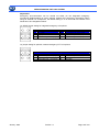
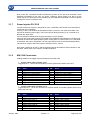
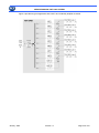
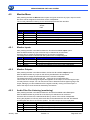
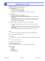
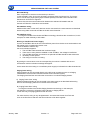
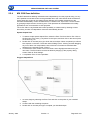
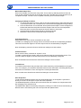
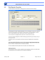
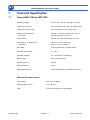
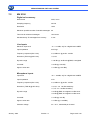
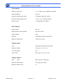
Cabling details for the trigger inputs and outputs of the MT 5708.
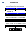
• Input line and output speaker (item 6 and 7 chapter 3.3.2):
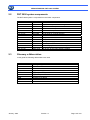
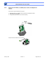
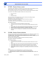
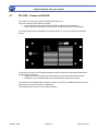
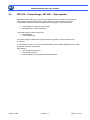
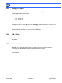
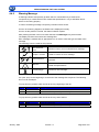
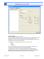
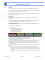
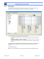
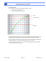
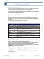
The illustration on the left shows the pin numbering of the built-in Phoenix terminal strips
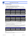
Pinouts of the four 2x4 Phoenix MDSTB2,5/4-G1-5.08
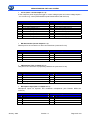
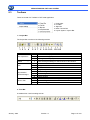
Pinout of the amplified signal inputs 1 - 4 labeled INPUT 1...4 “ and the loudspeaker line
outputs 1 - 4 labeled LS - OUT 1..
PIN
1
2
3
4
5
6
7
8
Left Connector
Signal
PA In 1 +
PA In 1 PA In 2 +
PA In 2 LS Out 1+
LS Out 1LS Out 2+
LS Out 2-
PIN
1
2
3
4
5
6
7
8
Right Connectr
Signal
PA In 3 +
PA In 3 PA In 4 +
PA In 4 LS Out 3+
LS Out 3LS Out 4+
LS Out 4-
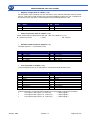
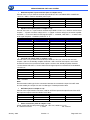
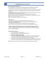
Pinout of the amplified signal inputs 5 - 8 labeled INPUT 5...8 “ and the loudspeaker line outputs
5 - 8 labeled LS - OUT 1
PIN
1
2
3
4
5
6
7
8
Left Connector
Signal
PA In 5 +
PA In 5 PA In 6 +
PA In 6 LS Out 5+
LS Out 5LS Out 6+
LS Out 6-
PIN
1
2
3
4
5
6
7
8
Right Connector
Signal
PA In 7 +
PA In 7 PA In 8 +
PA In 8 LS Out 7+
LS Out 7LS Out 8+
LS Out 8-
PA = Power Amplifier
LS = LoudSpeaker
Note:
For the monitoring of the loudspeaker lines, only 2 cable wires per loudspeaker are necessary.
Additional return lines from the loudspeakers to the MT 5708 are not required
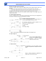
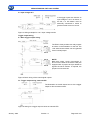
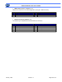
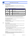
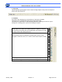
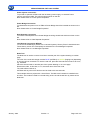
• Spare Amp (item 8 e 9 chapter 3.3.2)::
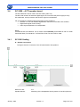
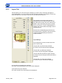
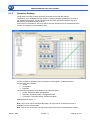
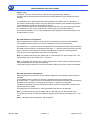
Pinouts of the 2 x 4-pin Phoenix terminal strips MDSTB2,5/4-G1-5.08, used for the amplified
standby inputs 1 and 2 (upper connector strip) and the amplified standby through outputs 1 and
2 (lower connector strip) Pinout of the amplified standby signal inputs labeled SB INPUT 1,2 “
and the amplified standby channel through outputs labeled „SB THRU 1,2
PIN
1
2
3
4
Signal
SBPA Through 1+
SBPA Through 1SBPA Through 2+
SBPA Through 2 -
PIN
5
6
7
8
Signal
SBPA In 1+
SBPA In 1SBPA In 2+
SBPA In 2-
SBPA = Stand-By Power Amplifier
Note:
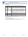
Recommended cable type for the amplified standby channel through connection of two MT
5708: Cross section = ≥ 0.52 mm2 / AWG20
January 2009
Version 1.2
Page 35 di 130