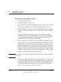
1
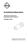
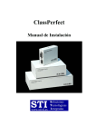
260
Solvent Vapor Exit Accessory
Theory of operation
The Solvent Vapor Exit (SVE) is a GC accessory for performing large volume
injections with a Cool On-Column inlet (COC). At the start of the run, the SVE
solenoid valve is open as the large volume sample is injected into the cool oncolumn inlet and moves into the retention gap. The precolumn separates most
of the solvent from the analytes and vents it through the open valve. At a time
specified by the user to optimize the analysis, the valve closes, the oven
temperature program begins, and the retained solvent and analytes move onto
the analytical column for separation.
Solvent Waste Port
Solvent Vent Valve
3
1
50 mm Bleed Restrictor
2
(SS) Transfer Line
Cool On-column Inlet
(SS) Union
Detector
320 mm
Transfer line
Column
Splitter
Retention
Gap
(5M, 530 mm)
Figure 260-1
Jun 2001
Retaining
Pre-Column
(2M, 250 mm)
HP-5MS
Analytical Column
(30M, 250 mm)
Solvent vapor exit accessory flow diagram
Inlets
Agilent 6890 Gas Chromatograph Service Manual
1 of 10
260
Solvent Vapor Exit Accessory
Replacement procedures
Replacement procedures
Replacing the valve/fitting assembly
WARNING
Hazardous voltages are present in the mainframe when the GC power cord is
plugged in. Avoid a potentially dangerous shock hazard by unplugging the
power cord before removing the side panels.
Caution
Prevent electrostatic voltages from damaging the GC by using precautions
such as an ESD wriststrap.
2 of 10
1.
Turn off the GC and unplug the power cord. Allow time for all heated
zones to cool and then turn off supply gases at their sources.
2.
Remove the top cover, the pneumatics cover, the electronics carrier cover,
and the right side cover.
3.
Remove the bleed restrictor column and the solvent vent waste line from
the valve fitting assembly.
Inlets
Agilent 6890 Gas Chromatograph Service Manual
Jun 2001
Solvent Vapor Exit Accessory
Replacement procedures
Heat resistant
tape
Bleed restrictor
column
Connect solvent
waste line
Stainless
tubing
Figure 260-2
Jun 2001
260
Removing the valve/fitting assembly (shown with valve driver
bracket installed)
4.
Inside the oven, disconnect the 320 µm transfer line from the stainless
union on the 1/16-inch stainless steel tubing. Carefully remove the tubing
from the oven through the cutout in the top of the oven.
5.
Disconnect the valve driver cable from the valve jumper cable or valve
driver assembly, as applicable.
6.
Remove the mounting screw in the valve/fitting assembly and remove the
assembly from the GC.
Inlets
Agilent 6890 Gas Chromatograph Service Manual
3 of 10
260
Solvent Vapor Exit Accessory
Replacement procedures
7.
Replace the valve/fitting assembly and mount it to the GC oven with the
screw. Cover the open end of the union to avoid contamination and route
the 1/16-inch stainless steel tubing and union into the oven. Repack the
insulation around the tabling. Connect the valve driver cable to the valve
jumper cable or valve driver assembly, as applicable.
8.
Use a new graphite/Vespel ferrule to reconnect the 320 µm transfer line
to the union.
9.
Examine the bleed restrictor column. If the column is damaged, replace
it with a new 0.5 m length of 50 m column, installing a new fitting and
ferrule. Be sure to trim 5 to 10 mm off the end of the new column after
installing the new fitting and ferrule.
10. Reattach the solvent waste vent line.
WARNING
Because a significant amount of solvent is vented through the SVE valve
assembly, it is important that the bleed restrictor and the solvent vent are
connected to an appropriate laboratory ventilation system.
11. Check for leaks.
Replacing the bleed restrictor column
4 of 10
1.
Turn off the GC and unplug the power cord. Allow time for all heated
zones to cool and then turn off supply gases at their sources.
2.
Remove the top cover and the right side cover. If necessary, also remove
the pneumatics cover and the electronics carrier cover.
3.
Using a wrench, remove the old bleed restrictor column.
4.
Cut a 0.5 m section off of the new 50 µm bleed column for use as the
restrictor.
5.
Attach a male fitting and ferrule to the restrictor column, then trim 5 to
10 mm from that end of the column.
6.
Connect the 0.5 m 50 µm bleed restrictor to the SVE valve.
Inlets
Agilent 6890 Gas Chromatograph Service Manual
Jun 2001
Solvent Vapor Exit Accessory
Replacement procedures
7.
260
Make a loop (or loops) in the excess column protruding from the valve
and move it to an unobstructive position.
•
Coil it in a loose coil (approximately 6 inch diameter).
•
Secure the coil with heat resistant tape or equivalent.
Replacing the tri-column assembly
Jun 2001
1.
Cool the inlet and detector.
2.
Turn inlet and detector gases off.
3.
Disconnect the Tri-column assembly from the COC inlet, detector and
(SS) union and remove the column assembly from the GC oven.
4.
Install the new SVE Tri-column assembly onto a column hanger and hang
the assembly inside the GC oven. Position the column assembly so that
the end of the retention gap (530 µm) is located under the COC inlet and
the end of the analytical column (250 µm) is under the detector.
5.
Connect the retention gap to the COC inlet using a graphite ferrule and
a column nut.
6.
If using a MSD, connect the analytical column (HP-5MS) to the MSD using
a column nut (part no. 05988-20066) and a graphite/Vespel ferrule
(part no.5062-3508). If using any other type of detector, connect the
analytical column (HP-5MS) to the GC detector using a column nut
(part no. 5181-8830) and a graphite/Vespel ferrule (part no. 5062-9527).
7.
Remove the stainless ferrules from the union. Use a graphite/Vespel
ferrule to connect the 0.5 m × 320 mm transfer line from the quartz Ysplitter of the Tri-column assembly to the unused end of the stainless
union located inside the GC oven.
8.
Check all of the connections for leaks using an electronic leak detector.
Inlets
Agilent 6890 Gas Chromatograph Service Manual
5 of 10
260
Solvent Vapor Exit Accessory
Replacement procedures
Replacing the pre-column assembly
Note
1.
Cool the inlet and detector.
2.
Turn inlet and detector gases off.
3.
Disconnect the Tri-column assembly from the COC inlet, the detector and
the (SS) union and remove the column assembly from the GC oven.
4.
Using a column cutter, cut the transfer column and the analytical columns
as close to the quartz Y-splitter as possible. Be sure to cut the columns
straight.
5.
Using the column cutter, trim the ends of the tri-column assembly
ensuring that the cuts are straight. Then use a lint free wipe and methanol
to clean any dirt and finger prints from approximately three to four
centimeters from each of the five column ends.
6.
Being careful not to touch the ends of the columns, insert them into the
quartz splitter as far as possible, making sure that the column ends are
making contact with the inside walls of the splitter. Sufficient pressure
should be applied to give a good seal. Too much pressure, on the other
hand, can damage the polyimide layer or even the column and result in
leakage. Test to see that the column has been installed correctly by trying
to pull the column out of the splitter using medium force. If the column
comes out easily, trim the end and insert again.
A concentric circle inside the splitter should result if the column is installed
correctly.
7.
6 of 10
After connecting the column ends into the quartz splitter, reconnect the
tri-column assembly inside the GC oven and increase the column head
pressure incrementally to the desired pressure. An incremental increase
is better than immediately applying the total column head pressure to
avoid a “shock” that can loosen the connection.
Inlets
Agilent 6890 Gas Chromatograph Service Manual
Jun 2001
Solvent Vapor Exit Accessory
Leak testing
260
Leak testing
When checking the solvent vapor exit assembly for leaks, first check the
tri-column assembly. If the tri-column assembly is not leaking, check the
valve/fitting assembly (which includes the stainless steel union, tubing, and
fitting on the solenoid).
Potential leak points
• Tri-column assembly
• Quartz column connector
• Quartz Y splitter
• Connection to the inlet
• Valve/fitting assembly
• Solenoid valve
• S/S union
• Inlet fitting on the valve/fitting assembly
Note that there are no replacement parts on the valve/fitting assembly. If the
valve fails or the fitting cannot be tightened, replace the assembly.
Leak testing the tri-column assembly
Tools Required
The following tools (not supplied in the SVE Kit) are required to perform the
leak check procedure of the tri-column assembly.
•
•
1/16-inch (SS) union (part no. 0100-0124)
Vespel/graphite ferrules:
• For 250 µm column (part no. 5062-3508)
•
•
•
•
Jun 2001
For 320 µm column (part no. 5062-3506)
1/8-inch Swagelok nut (part no. 5180-4103)
1/8-inch solid (no hole) vespel ferrule (part no. 0100-1372) or
1/8-inch Swagelok cap
Electronic leak detector (optional)
Inlets
Agilent 6890 Gas Chromatograph Service Manual
7 of 10
260
Note
8 of 10
Solvent Vapor Exit Accessory
Leak testing
1.
Replace the septum of the Cool On-column inlet.
2.
Using a 1/16-inch (SS) union and the appropriate graphite/Vespel
ferrules, connect the detector end (250 µm) of the tri-column assembly
and the transfer line (320 µm) together.
3.
From the 6890 GC keyboard, set the inlet pressure to 50 psi and wait
approximately 15 seconds for equilibration.
If pressure can not be reached, either a very large leak is present or the supply
pressure is not high enough (at least 10 psi greater than desired pressure).
4.
Cap the septum purge vent of the Cool On-column flow module using a
solid (no- hole) 1/8-inch Vespel ferrule (part no. 0100-1372) and a 1/8inch Swagelok nut (part no. 5180-4103). As an alternative a 1/8-inch
Swagelok cap can be used.
5.
From the GC keyboard, turn the inlet pressure “OFF”.
6.
Note the “Actual” reading on the display and monitor for 10 minutes. You
can use the stopwatch feature of the 6890 GC to monitor the time by
pressing [Time] and then [Enter] to start timing.
7.
If there is less than 1.5 psi pressure loss, consider the system to be leak
tight.
8.
If pressure loss is much greater than 1.5 psi, there is a leak that must be
found and corrected.
Inlets
Agilent 6890 Gas Chromatograph Service Manual
Jun 2001
Solvent Vapor Exit Accessory
Leak testing
260
Leak testing the SVE assembly
Jun 2001
1.
Cool the oven and inlet.
2.
With only the carrier gas flowing through the GC and column, close the
SVE solenoid valve.
3.
Use an electronic leak detector to check for leaks. Detection fluid may be
used on the valve assembly, but be sure to avoid contaminating the oven
or electrical connections. Clean up any fluid after use.
4.
If a leak is found at a connection, tighten the fitting or replace the seals.
If there is a leak through the valve, replace the valve/fitting assembly.
Inlets
Agilent 6890 Gas Chromatograph Service Manual
9 of 10
260
10 of 10
Solvent Vapor Exit Accessory
Leak testing
Inlets
Agilent 6890 Gas Chromatograph Service Manual
Jun 2001