1
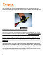
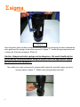
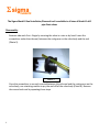
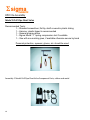
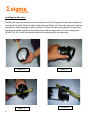
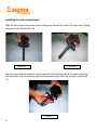
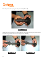
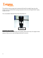
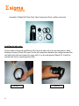
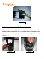
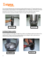
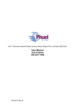
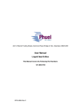
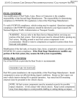
Sigma Metals Ltd.
Drill Pipe Float Valve Repair Service Manual
Model F Drill Pipe Float Valve
Model G Drill Pipe Float Valve
Purpose
The Sigma Metals Limited (SML) Repair Service Manual is intended to provide guidance for the
servicing of Model F and Model G Drill Pipe Float Valves (DPFV).
Additional Product Information
The Sigma Metals Limited catalog, available separately, provides the DPFV part numbers for the DPFV
assemblies as well as the part numbers for the appropriate repair kits. The catalog also shows the
parts that are included in repair kits for metal parts, Metal Repair Kit (MRK) and the parts that are
included in repair kits for rubber parts, Rubber Repair Kits (RRK).
The catalog also provides the ordering information for drill pipe float valves that are for specific service
applications. These service applications include standard service, H2S (Sour Gas) service, and those
requiring resistance to higher temperatures. The catalog also indicates the appropriate repair kits for
each specific service application. The selection of the appropriate service application-specific products
must be made by the customer based on their individual working environments and design criteria.
Drill Pipe Float Valve Repair & Service Manual
Table of Contents
Valve Disassembly
Page
Model F Drill Pipe Float Valve----------------------------------1-3
Model G Drill Pipe Float Valve----------------------------------4-7
Drill Pipe Float Valve Inspection Procedure------------------------8-9
Valve Reassembly
Model F Drill Pipe Float Valve--------------------------------10-15
Model G Drill Pipe Float Valve--------------------------------16-20
DPFV Disassembly
Model F DPFV
Recommended Tools:
1 – Standard screwdriver, flat tip, shaft covered in plastic tubing
1 – Hammer, plastic-tipped is recommended
1 – General purpose pliers
1 – Sigma Model ‘’F’’ spring compression tool if available
1 – Vise with non-marking jaws, if available otherwise secure by hand
Personal protection, eyewear, gloves, etc. should be used
Disassembly:
Remove side seals first – Begin by securing the valve in a vise or by hand on a sturdy work
surface. Insert the screwdriver under the side seal, between the seal groove on the valve
body and the seal (Photo 1).
1
Photo 1
Once the screwdriver is securely inserted between the side seal and the valve body, use a
twisting motion to pry the seal off of the valve body (Photo 2). Remove the second side seal by
repeating these steps.
Photo 2
Remove internal DPFV parts, piston valve and components:
Place the DPFV on a stable, flat work surface. The valve should be standing on end, with the
end of the valve with the side seal grooves closest to the table. Care should always be taken
to maintain pressure on the valve guide while depressing the valve compression spring.
Caution: Compressed valve springs can be dangerous; this work should only be
performed by trained personnel using the proper tools and appropriate safety
equipment.
The smaller size valve springs can be compressed by hand; larger size valve springs require a
specialized valve spring compression tool, such as the Sigma Model F spring compression tool.
Rotate the valve shaft out of the cage while maintaining pressure on the valve guide. Carefully
and slowly release the pressure on the valve spring until the spring is no longer compressed.
Once the pressure has been released from the valve spring, remove the valve stem from the
valve body while maintaining pressure on the valve guide.
2
Photo 3
Once the piston valve has been removed and the pressure on the spring has been released the
valve guide and the spring can be safely removed. A Sigma ‘’F’’ model spring compression tool
is shown for illustrative purposes. (Photo 3 )
Caution: Compressed valve springs can be dangerous, this work should only be
performed by trained personnel using the proper tools and appropriate safety
personal protection equipment.
The smaller size valve springs can be compressed by hand for assembly; larger size valve
springs require a Sigma ‘’F’’ Model valve spring compression tool.
3
DPFV Disassembly
Model G DPFV
Recommended Tools:
1 – Standard screwdriver, flat tip, shaft covered in plastic tubing
1 – Hammer, plastic-tipped is recommended
1 – General purpose pliers
1 – Sigma Model G Seal Installation/Removal Tool, for the insertion and
removal of the steel valve seal retaining ring
1 – Vise with non-marking jaws, if available otherwise, secure by hand
1 - ‘’H’’ frame hydraulic press if available
Personal protection, eyewear, gloves, etc. should be used
An ‘’H’’ frame hydraulic press, if
available, is recommended to be used
along with the Sigma Model G Seal
Installation Tool to remove and re-install
the valve seal retaining ring. An example
of this equipment is pictured in the
photo on the right.
This equipment should only be used by
personnel that have been trained in how to
use it safely and using appropriate safety
equipment
4
Photo 4
The Sigma Model G Seal Installation/Removal tool is available in all sizes of Model G drill
pipe float valves
Disassembly:
Remove side seals first – Begin by securing the valve in a vise or by hand. Insert the
screwdriver under the side seal, between the seal grove on the valve body and the seal
(Photo 5).
Photo 5
Once the screwdriver is securely inserted between the side seal and the seal groove on the
valve body, use a twisting motion to pry the seal off of the valve body (Photo 6). Remove
the second side seal by repeating these steps
5
Photo 6
Removing flapper assembly components:
Using the pliers, remove the flapper hinge pin that secures the flapper to the valve
body by pulling one end of the pin out of the lugs (Photo 7).
Photo 7
6
Removing the seal and the retaining ring:
If the steel retaining ring is to be removed, using the Sigma Model G Seal installation/Removal
Tool and a hydraulic press is recommended to safely remove the ring. The steel cylinder,
shown in the recommended tools illustration, must be made of the appropriate diameter on
one end to fit inside the cage and be small enough that it engages the retaining ring and can
be pressed out of the cage. The other end of the steel cylinder should be of the appropriate
diameter to press the seal back in place when being re-assembled.
Removing the rubber shock absorber:
Place the DPFV on a stable, flat work surface with the end of the valve with shock absorber in
the upward position. Insert the standard, flat-tipped screwdriver between the top of the valve
and the rubber shock absorber. Once the screwdriver is securely inserted between the side
seal and the seal groove on the valve body use a twisting motion to pry the seal off of the
valve body (Photos 8, 9, 10)
Photo 8
Photo 9
Photo 10
7
DPFV Inspection
Preparation:
It is recommended that all disassembled parts be appropriately cleaned to remove
accumulated corrosion, etc.
All rubber component parts should be discarded and replaced with new rubber. The
replacement rubber parts must be the appropriate type of rubber for each given service
application, i.e. Viton for high temperature service, HNBR for H2S (Sour Gas) Service, and
BUNA, NBR for standard service applications.
Model F Drill Pipe Float Valve Inspection
The person who does this inspection should be trained in what to look for when inspecting the
valve. The proper level of training will enable the person doing the inspection to know what to
look for and how to know which parts should be replaced. This person should also be trained
to know at what point the entire drill pipe float valve needs to be replaced.
Visual Inspection:
The visual inspection should look or evidence of excessive wear. The primary area of
inspection should include:
• Examine the cage for evidence of ‘’wash-out or erosion’’ in any of the sealing areas.
Washout means an area of metal that has been eroded especially in the sealing areas
• The valve should be free of evidence of ‘’wash-out or erosion’’
• Compare the condition of the metal parts that were removed with the parts in metal
repair kit.
• All rubber component parts should be discarded and replaced with new rubber each
time the valve is inspected/repaired.
8
Model G Drill Pipe Float Valve Inspection
The person who does this inspection should be trained in what to look for when inspecting the
valve. The proper level of training will enable the person doing the inspection to know what to
look for and how to know which parts should be replaced. This person should also be trained
to know at what point the entire drill pipe float valve needs to be replaced.
Visual Inspection:
The visual inspection should look or evidence of excessive wear. The primary area of
inspection should include:
• Examine the cage for evidence of ‘’wash-out or erosion’’ in any of the sealing areas.
Washout means an area of metal that has been eroded especially in the sealing areas
• The flapper should be free of evidence of ‘’wash-out or erosion’’
• Compare the condition of the metal parts that were removed with the parts in metal
repair kit.
All rubber component parts should be discarded and replaced with new rubber each
time the valve is inspected/repaired.
9
DPFV Re-Assembly
Model F Drill Pipe Float Valve
Recommended Tools:
1 – Standard screwdriver, flat tip, shaft covered in plastic tubing
1 – Hammer, plastic-tipped is recommended
1 – General purpose pliers
1 – Sigma Model ‘’F’’ spring compression tool if available
1 – Vise with non-marking jaws, if available otherwise secure by hand
Personal protection, eyewear, gloves, etc. should be used
Assembly: F Model Drill Pipe Float Valve Component Parts, rubber and metal
10
Installing the side seals:
Position the cage on the work surface so that the end of the cage with the side seal grooves
away from the table. Oil the inside of each side seal (Photo 11). Place the side seal in the top
seal groove, while holding it in place, (Photo 12) insert the flat tip screwdriver between the
seal groove and the seal and rotate the seal around the cage until it is in the seal groove
(Photo 13 & 14). Install the second side seal by repeating this previous step.
Photo 11
Photo 13
11
Photo 12
Photo 14
Installing the valve components:
Slide the valve seal on the piston valve making sure that the flat side of the valve seal if facing
the piston valve (Photo 15 & 16)
Photo 15
Photo 16
Slide the valve seal disc onto the piston valve shaft with the flat side of the valve seal facing
the valve seal. Slide the seal disc onto the valve seal so that it fits into the valve seal (Photo
17).
Photo 17
12
Place the piston valve spring onto the piston shaft (Photo 18).
Photo 18
Holding the valve assembly in one hand, slide the valve guide onto the piston valve shaft so
that the valve guide fits into the valve spring (Photos 19 & 20).
Photo 19
13
Photo 20
Place the valve guide inside the valve spring so that it fits inside the spring (Photo 21)
Photo 21
Position the piston valve assembly into the cage until the piston shaft is through the slot in the
cage. If doing this by hand on a smaller valve spring size, carefully release the compression so
that the valve guide seats securely in the cage.
Caution: Compressed valve springs can be dangerous, this work should only be
performed by trained personnel using the proper tools and appropriate safety
personal protection equipment.
14
The smaller size valve springs can be compressed by hand for assembly; larger size valve
springs require a specialized valve spring compression tool such as the Sigma Model F spring
compression tool.
The re-assembled F Model Drill Pipe Float Valve (Photo 22)
Photo 22
Inspection of the assembly:
Review the assembly steps and make sure the piston valve moves freely in the cage and seals
properly. Make sure the valve retaining mechanism fits securely.
15
DPFV Re-Assembly
Model G Drill Pipe Float Valve
Recommended Tools:
1 – Standard screwdriver, flat tip, shaft covered in plastic tubing
1 – Hammer, plastic-tipped is recommended
1 – General purpose pliers
1 – Sigma Model G Seal Installation/Removal Tool, for the insertion and
removal of the steel valve seal retaining ring
1 – Vise with non-marking jaws, if available otherwise secure by hand
1 - ‘’H’’ frame hydraulic press if available
Personal protection, eyewear, gloves, etc. should be used
The Sigma Model G Seal Installation/Removal tool is available in all sizes of Model G drill
pipe float valves
16
Assembly: G Model Drill Pipe Float Valve Component Parts, rubber and metal
Installing the side seals:
Oil the inside of each side seal (Photo 23). Place the side seal in the top seal groove, while
holding it in place, (Photo 24) insert the flat tip screwdriver between the seal groove and the
seal and rotate the seal around the cage until it is in the seal groove (Photo 25). Install the
second side seal by repeating these steps
Photo 23
17
Photo 24
Photo 25
Installing the seal retaining ring (steel) and the valve seals (rubber):
Position the cage on the work surface so that the end of the valve with the side seals is closest
to the work surface as shown. Before the valve seal is put in place, a visual inspection of the
seal groove should be done to make sure it is free of debris. Insert the seal into the groove
With the valve seal securely in place, place the seal retaining ring (steel) into the valve seal
(Photo 26 & 27)
Photo 26
18
Photo 27
It is recommended that the seal retaining ring be installed using an ‘’H’’ frame hydraulic press
(Photo 4)and the Sigma Model G Seal Installation/Removal tool (Photos 28 & 29)as mentioned
previously in this manual. If these are available and the person doing the repair must be
trained on how to correctly and safely conduct the repair using this equipment.
Photo 28
Photo 29
Installing the flapper assembly:
Insert the flapper into the cage and align the pin holes in the flapper with the pin holes on the
lug (Photo 30). Place the torsion spring assembly onto the flapper, hold in place with one
hand, and insert the pin into position (Photo 31).
Photo 30
19
Photo 31
Install the shock absorber:
Place the cage on the work surface so that the end with the side seals is closest to the work
surface. Position the shock absorber onto the end of the cage (Photo 32). Insert the flat tipped
screwdriver between the top of the cage and the shock absorber (Photo 33). Twist the
screwdriver around the cage until the shock absorber seats itself onto the end of the cage.
Photo 32
Photo 33
Inspection of the assembly:
Review the assembly steps and work the flapper open and closed to make sure that it moves
freely and seats properly on the seal. Make sure the flapper retention mechanism fits securely.
Lift the flapper and release, letting the spring ‘’snap’’ the flapper closed. A firm metal on
rubber sound should be heard. If a metal on metal sound is heard, this could indicate an
assembly problem and the spring assembly and the flapper assembly should be removed, reinstalled, and re-inspected.
20