1
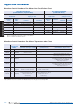
APPLICATION INFORMATION
Application Information
AGENCY LISTINGS
UL and CSA
Where applicable, Marathon Electric’s motors are UL Listed for
explosion proof enclosures, UL Recognized construction for
non-explosion proof enclosures, and UL Recognized as a
motor/protector combination. Our motors are also CSA Certified
for both explosion proof and non-explosion proof enclosures.
AC Motors
Non-Explosion Proof
UL File No.
NEMA 48-449 Frame
E49747
NEMA 500 and 5000 Frame
—
IEC 63-90 Frame
E49747
IEC 100-280 Frame
E49747
* Does not include coverage for use with VFD
#
Domestic product only
CSA File No.
LR2025
LR2025*
LR2025
LR2025#
Explosion Proof
UL File No.
CSA File No.
NEMA 56-326 Frame
NEMA 364-449 Frame
E12044
E12044
LR47504
LR21839
Fire Pump Motors
UL File No.
CSA File No.
NEMA 143-510
EX5190
LR2025
UL File No.
CSA File No.
E57948
LR33543
PMDC Motors
Non-Explosion Proof
NEMA -56-145
CE (Conformity Europeanne)
CE marking on the nameplates of Marathon Electric motors is
available upon request. Note that only the "Low Voltage"
directive applies to electric motors. Contact a factory
representative for details. Non-explosion proof microMAX™,
BlackMax® and BlueMax® (TENV and TEFC) standard (catalog)
models have the CE Mark on the nameplate.
ATEX Directive (Atmospheres Explosibles)
Mandatory by law, the European Union (EU) Directive 94/9/EC
requires that electric motors in contact with a potential ignition
source carry the CE mark, notified body identifier, Ex symbol,
equipment group and category, plus the date code.
NEMA (National Electrical Manufacturers Ass’n)
All Marathon Electric motors are manufactured in accordance
with all applicable NEMA standards in MG1-2003. When
applied in accordance with the "Guidelines for Application of
Three Phase Motors on Variable Frequency Drives", Marathon
Electric motors are in full compliance with NEMA MG12003, Part 31, Section 4.4.2, as pertaining to voltage spikes.
460 volt motors must withstand voltage spikes of up to 1426
volts; 575 volt motors must withstand spikes up to 1788 volts.
See "Insulation Systems" for additional detail on this subject.
Commitment to RoHS and WEEE European
Directives
European Directive 2002/95/EC “Restriction of Use of Certain
Hazardous Substances” (RoHS) and Directive 2002/96/EC
“Directives on Waste Electrical and Electronic Equipment”
(WEEE) were enacted to control the amount of certain
hazardous substances contained in products shipped into the
E.U. Restricted substances include lead, mercury, cadmium,
hexavalent chromium, polybrominated biphenyls and
polybrominated dipheynl ethers.
10
The scope of products covered, affecting motors, is:
• Large household appliances
• Small household appliances
• IT and telecommunications equipment
• Consumer equipment
• Electrical and electronic tools (except large scale stationary
and industrial tools)
• Toys, leisure and sports equipment
• Automatic dispensers
In addition to the exemption above, the Directives do not
currently apply to medical devices, monitoring and control
instruments, spare parts for the repair or reuse of electrical and
electronic equipment placed on the market before July 1, 2006,
and most military and state security equipment.
Regal Beloit Corporation worked closely with suppliers to
assure that product falling within the scope of these directives
meets the specified levels of these substances. The directives
took affect July 1st, 2006 however many products were
converted in May and June. The products converted are motors
in NEMA frame size 145 and below, both AC and DC motors
with the following exceptions:
• Sleeve bearing motors (an exemption has been applied
for). A compliant ball bearing equivalent motor can be
ordered.
• Brake motors in 56-145 frame will have to be ordered
specifically as RoHS compliant.
• Some motors with specialty electro-mechanical components.
BEARINGS
FRAME SIZE
STANDARD TYPE
COMMENTS
48
Shield Ball
Sleeve bearing as noted
56 - 145T
Sealed Ball
182 - 444T
Double Shield Ball
284 - 449TS
Single Shield Ball
445T - 6805
Double Shield Ball
Direct - coupled loads
445T - 6805
Roller (DE)/Ball
Belted loads
* Belting data must be provided on all belted applications
Standard horizontal motors can be mounted in a vertical shaft
down orientation (except brakemotors). Contact a factory
representative for shaft up mounting arrangements.
Marathon Electric motors employ the use of Mobil POLYREX®
EM grease, a specially formulated bearing grease designed for
electric motors. POLYREX® EM provides superior lubricity,
durability and resists corrosion, rust and washout. POLYREX®
EM is a registered trademark of Mobil Corporation.
Maximum safe mechanical speed capability is a function of
bearing size, type and grease selection, as well as rotor balance
specifications. Consult the “Maximum Safe Mechanical Speed
Limits” chart in the “Overspeed Capability” section.
Note that these values do not imply maximum constant
horsepower RPM.
SB300 – Prices and Specifications are subject to change without notice.
Application Information
ELECTRICAL TYPE/STARTING METHOD
Motors in this catalog are capacitor start, split phase,
permanent split capacitor, or three phase. Capacitor Start
motors have high starting torque, high breakdown torque, and
relatively low starting current. Split phase motors have medium
starting torque and medium starting current. Permanent split
capacitor motors have low starting torque and low starting
current. Three phase motors have high starting, extra
breakdown torque, and typically very low starting current.
Single phase motors cannot be applied on variable frequency
drives with three phase output.
ENCLOSURE AND METHOD OF COOLING
Marathon Electric motors are available in various enclosures;
Dripproof (DP), Dripproof Force Ventilated (DPFV), Totally
Enclosed Fan Cooled (TEFC), Totally Enclosed Non-Ventilated
(TENV), Totally Enclosed (TEAO) and Totally Enclosed Blower
Cooled (TEBC). Application conditions will determine the type
of motor enclosure required.
Dripproof motors have open enclosures and are suitable for
indoor use and in relatively clean atmospheres. Dripproof
motors have ventilating openings constructed so that drops of
liquid or solid particles falling on the machine at an angle of not
greater than 15 degrees from the vertical cannot enter the
machine.
Totally enclosed motors are suitable for use in humid
environments or dusty, contaminated atmospheres. Totally
enclosed non-ventilated motors are NOT cooled by external
means. Totally enclosed fan cooled motors are cooled by
external means that are part of the motor but not in the
internal workings of the motor. Totally enclosed air over
motors are sufficiently cooled by external means, provided
by the customer.
North American installations
North American standards for electric motors generally fall into
one of two divisions. Division 1 Explosion Proof motors are UL
Listed in accordance with NFPA Class I (Flammable Gases) or
Class II (Combustible Dusts) and Groups (gases or dusts),
depending upon the atmosphere. Division 2 motors are CSA
Certified and are marked similarly to Division 1 equipment.
Inverter Duty motors through 449T are CSA Certified for use in
Division 2 locations.
European installations
Motors for hazardous locations in Europe must meet a
different set of standards and require different markings than
those of North America. CENELEC sets the standards for
equipment in hazardous locations for Europe. Motors for
explosive atmospheres in Europe are often referred to as
flameproof or non-sparking motors. These motors must comply
with the ATEX Directive. The ATEX Directive covers all
electrical equipment used in explosive atmospheres. To ensure
compliance with the Directive, equipment must meet the
essential ATEX requirements and carry the CE mark on the
nameplate. Other information required on the nameplate is the
Ex symbol, group & category, date code, EEx, protection
method, gas group, and temperature code. (Example: EEx d
IIB T4 CE0359 Ex II 2 G/D 2004)
The tables on page 12 describe Marathon Electric’s
capabilities by Area Classification and by
Temperature Code.
IEC DEGREES OF PROTECTION vs. MARATHON
ELECTRIC’S STANDARD CONSTRUCTION
The enclosure terminology for an IEC motor is a
combination of the IP (Ingress Protection) and IC (Inherent
Cooling) codes. Each number in the IP code stands for a
different degree of protection.
IP12 - Dripproof
IP22 - Dripproof with screens, or die cast aluminum
bracket
IP43 - Totally Enclosed
IP54 - Totally Enclosed Severe Duty
IP55 - Totally Enclosed Severe Duty with V-Ring Shaft
seals, and/or “Smart Ring” rotating shaft seal and
Neoprene gaskets
IP56 - Totally Enclosed Severe Duty with rotating Shaft
seals (eg. Inpro/Seal VBX bearing isolator) and
Neoprene gaskets
HAZARDOUS DUTY™
Hazardous Duty™ motors are totally enclosed (fan cooled or
non-ventilated) motors designed for applications in
hazardous atmospheres containing explosive gases and/or
combustible dusts.
SB300 – Prices and Specifications are subject to change without notice.
11
APPLICATION INFORMATION
EFFICIENCY
The efficiency of a motor is the ratio of its useful power output
to its total power input and is usually expressed in a
percentage. Marathon Electric offers standard, high efficient
EPAct, and premium efficient (XRI®) ratings. Standard
efficiency motors may only be used on applications that are
exempt from EPAct. The high efficient motor line is in
compliance with the Energy Policy Act of 1992 (EPAct) and/or
Canadian efficiencies as set by NRCan. The XRI® line is a
premium efficiency line, which exceeds mandated efficiencies
of EPAct and /or NRCan. Unless otherwise noted, XRI ®
premium efficient motors in this catalog meet NEMA Premium®
the newly promoted efficiency levels by NEMA and the
Consortium for Energy Efficiency (CEE).
Application Information
Marathon Electric Hazardous Duty Motor Area Classification Chart
Class I Area Classification
(Flammable Gases, Vapors or Mists)
Europe - ATEX
(Category G - Gases)
North America
APPLICATION INFORMATION
Division 1
Explosion
Proof
Division 2
TEFC &
TENV
Group A ①
Group B ①
①
Class II Area Classification
(Combustible Dusts)
Europe - ATEX
(Category D - Dusts)
North America
Zone1
Flameproof
Zone 2
Non-Sparking
Division 1
Explosion
Proof
Division2
Zone 21
Flameproof
Zone 22
Non-Sparking
Group A
Group IIC, Category G ①
Group IIC, Category G
-
-
-
-
Group B
Group IIC, Category G ①
Group IIC, Category G
-
-
-
-
Group C
Group C
Group IIB, Category G
Group IIB, Category G
-
-
-
-
Group D
Group D
Group IIA, Category G
Group IIA, Category G
-
-
-
-
-
-
-
-
Group E ①
-
-
-
-
-
-
-
Group F
Group F ①
Category D
-
-
-
-
-
Group G
Group G ①
Category D
-
Group is not applicable to that Division or Zone, or is not defined.
Group is not available from Marathon Electric.
Marathon Electric Hazardous Duty Motor Temperature Code Chart
Division 1 Explosion Proof/Zone 1 Flameproof
TEMPERATURE
CODES
Temp.
UL/CSA
Class I Area Classification
(Flammable Gases, Vapors or Mists)
ATEX
Division 1/Zone 1
Explosion Proof - Class I, Group D
(Group C as noted)
Division 2/Zone 2 Non-Sparking
Class II Area Classification*
(Combustible Dusts)
Division 1/Zone 21
Class I Area Classification
(Flammable Gases, Vapors or Mists)
Division 2/Zone 2
280OC
T2A
T2(280)
260OC
T2B
T2(260)
XRI® Severe Duty & IEEE-841 @ 1.15 S.F.,
Class I, Groups A,B,C,D (Sine wave power)
215OC
T2D
T2(215)
Available through Marathon's Mod Central
on Totally Enclosed EPAct, XRI®, XRI® Severe Duty
or IEEE-841 @ 1.0 S.F. on PWM VFD,
Class I, Groups A, B, C, D
200OC
T3
T3
Available through Marathon's Mod Central
on Totally Enclosed EPAct, XRI®, XRI® Severe Duty
or IEEE-841 @ 1.0 S.F., Sine wave power
Class I, Groups A, B, C, D
165OC
T3B
T3(165)
Explosion Proof - Class I, Group D
(Group C as noted), Sine wave
or PWM power
Explosion Proof - Class II,
Groups F & G, Sine wave
or PWM power
160OC
T3C
T3(160)
Available through Marathon’s Mod
Central on Explosion Proof - Class I,
Group C & D @ 1.0 S.F. Contact Factory
Available through Marathon’s Mod
Central on Explosion Proof - Class II,
Group F & G @ 1.0 S.F. Contact Factory
135OC
T4
T4
ATEX compliant motors
ATEX compliant motors
* Class II, Division 2 motors are not available from Marathon Electric, Zone 22 groups are not defined by ATEX.
12
SB300 – Prices and Specifications are subject to change without notice.
INSULATION SYSTEMS
Class B – General Purpose motors that employ Class B
insulation systems have a total temperature rating of 130°C
and maximum allowable temperature rise of 80°C at 1.0 S.F.
NEMA SERVICE FACTOR RATINGS
The table below lists the NEMA service factors for single
phase, dripproof motors. Totally enclosed and explosion
proof motors have 1.0 service factor except where noted.
Class F – Motors with a Class F system have a total
temperature rating of 155°C, with a maximum temperature
rise of 105°C at 1.0 S.F. Many Marathon Electric designs
utilize a Class F system but limit temperature rise to no
higher than "B" rise, providing thermal "headroom" for
longer insulation life.
Single Phase
NEMA SERVICE FACTOR @ RPM LISTED
Class H – Class H insulated motors have a total
temperature rating of 180°C and maximum allowable
temperature rise of 125°C. All Marathon Electric motors
that employ a Class H system are designed to operate
between "B" and "F" rise, giving the user a generous
thermal cushion.
"CR 200" – Corona Resistant, 200° rated magnet wire is
utilized in numerous general purpose and inverter duty
motor designs to extend insulation life under the rigors of
steep fronted voltage spikes, common with today’s IGBT
inverters. Refer to page 14 for product lines that employ
the use of CR200 magnet wire.
Motors with the CR200 insulation system can be operated at
up to 475 feet from the drive on 460 volt systems, at 3 KHz
carrier frequency. For other voltages and/or carrier
frequency combinations, contact a factory representative.
MAX GUARD ® – All Black Max®, Blue Max®, Blue Chip®,
XRI® Severe Duty and XRI®-841 (IEEE841) motors feature
the MAX GUARD® insulation system, either in conjunction
with Class F or Class H materials. Combining coronaresistant magnet wire (CR 200) with our patented "low
stress" winding configuration and uncompromising quality
standards, MAX GUARD® delivers long, dependable motor
life under the adverse thermal and dielectric stresses
imposed by IGBT-based variable frequency drives. MAX
GUARD ® surpasses the requirements of NEMA
MG1-2003, Part 31, Section 4.4.2.
460 Volt (or lower) motors equipped with
MAX GUARD ® can be operated at any distance
from the drive and at any carrier frequency. 575
Volt motors can be operated at up to 650 feet
cable length at 3 KHz.
MOUNTING
Most Marathon Electric motors are designed for horizontal
mounting (shaft parallel with ground), unless designed
otherwise, such as Vertical P Base motors. As a general
rule, a horizontal motor can also be mounted in a vertical
shaft down orientation. Horizontal motors should never be
mounted in a vertical shaft up orientation without consulting
your application engineer, as this practice can cause
damage to the motor, which is not covered under warranty.
Brakemotors should not be mounted vertically (up
or down), unless the brake has been specifically designed
for such.
SB300 - Prices and Specifications are subject to change without notice.
HP
1/12
1/8
1/6
1/4
1/3
1/2
3/4
1
1.5 & Up
3600
1.4
1.4
1.35
1.35
1.35
1.25
1.25
1.25
1.15
1800
1.4
1.4
1.35
1.35
1.35
1.25
1.25
1.15
1.15
1200
1.4
1.4
1.35
1.35
1.35
1.25
1.15
1.15
1.15
900
1.4
1.4
1.35
1.35
1.35
1.15
1.15
1.15
1.15
OVERLOAD PROTECTION
There are four choices in protection: manual (inherent
type), automatic (inherent type), thermostats, and none. A
manual overload must be physically reset to restart the
motor. An automatic thermal overload will stop the motor
when it is overloaded or overheated and restart it after the
motor has cooled down. None means the motor has no
protection. Thermostats are embedded in the winding and
connected to the motor starter control circuit. Marathon
Electric’s standards are normally closed thermostats, one
per phase.
A motor with an automatic reset
protector must not be used where
automatic restarting (after motor cooldown) would endanger personnel or
equipment. Such applications should
use a manual reset protector.
PHASE/POWER SUPPLY
Is the power supply three phase or single phase? Most
home and farm applications require single phase motors.
While most factories, large commercial and industrial users
require three phase motors. Single phase motors can be
used on three phase systems. Three phase motors,
however, cannot be operated from single phase systems.
Motor damage will result.
ROTATION
Most motors in this catalog are reversible by electrical
reconnection or by physical orientation.
Marathon
Electric’s standard rotation from the factory for single
phase motors is counterclockwise, when viewing the
opposite shaft end of the motor
SPEED/RPM
3600, 1800, and 1200 are the most common 60 HZ
synchronous speeds with full load speed equivalents of
3450, 1725, and 1150.
13
APPLICATION INFORMATION
Application Information
Application Information
TERMINOLOGY
Ambient Temperature – Temperature of the medium, such as
air, water or earth, into which the heat of the equipment is
dissipated.
Ampere (AMP) - A measure of the rate of current through
the motor.
APPLICATION INFORMATION
Base Speed – Nameplate rating where the motor will develop
rated HP at rated load and voltage. With AC systems, it
is commonly the point where 60 Hz is applied to the
induction motor.
Breakaway Torque – The torque required to start a machine
from standstill.
Breakdown Torque (BDT) – The maximum torque that an AC
motor will develop with rated voltage applied at rated
frequency while rotating.
Cogging – A condition in which a motor does not rotate
smoothly but "steps" or "jerks" from one position to another
during shaft revolution. Cogging is most pronounced at low
motor speeds and can cause objectionable vibrations in the
driven machine.
Continuous Duty – The continuous rating is the maximum
constant load that can be carried continuously without
exceeding established temperature rise limitations under
prescribed conditions of load and within the limitations of
established standards.
Definite Purpose Motor – Any motor design, listed and
offered in standard ratings with standard operating
characteristics and mechanical construction, for use under
service conditions other than usual or for use on a
particular type of application (NEMA).
Duty Cycle – The relationship between the operating and
resting times or repeatable operation at different loads
and/or speeds.
Efficiency – Ratio of power output to power input indicated as
a percentage. In motors, it is the effectiveness with which a
motor converts electrical power into mechanical power.
Frequency – Number of cycles per second of alternating
current 60HZ used primarily in the United States, 50HZ
normally used overseas.
Full Load Torque (FLT) – The torque necessary to produce
rated horsepower at full load speed.
General Purpose Motor – This motor has a continuous duty
rating and NEMA A or B design, listed and offered in standard
ratings with standard operating characteristics and mechanical
construction for use under usual service conditions without
restriction to a particular application or type of application
(NEMA).
14
Inertia – A measure of a body’s resistance to changes in
velocity, whether the body is at rest or moving at a constant
velocity. The velocity can be either linear or rotational. The
moment of inertia (WK2) is the product of the weight (W) of an
object and the square of the radius of gyration (K2). The radius
of gyration is a measure of how the mass of the object is
distributed about the axis of rotation. WK2 is usually
expressed in units of lb-ft2.
Intermittent Duty – A motor that never reaches
equilibrium temperature, but is permitted to cool down (to
ambient temperature) between operations. For example, a
crane, hoist or machine tool motor is often rated for 15, 30 or
60 minute duty.
Load Sharing – An application condition in which two or more
similar-sized AC Induction motors are mechanically connected
to each other and powered from the same inverter. Optimum
load sharing is achieved with higher slip (NEMA Design B or C)
motors.
Locked Rotor Current (LRA) – Steady state current taken
from the line with the rotor at standstill, at rated voltage and
frequency. This is the current when starting the motor and load
across the line.
Locked Rotor Torque (LRT) – The minimum torque that a
motor will develop at rest for all angular positions of the rotor,
with rated voltage applied at rated frequency.
No Load (Conditions) – The state of a machine rotating at
normal speed under rated conditions, but when no output is
required from it.
Power Factor – Power factor is the ratio of real power (kW) to
total kVA, or the ratio of actual power (W) to apparent power
(volt-amperes).
Reactance – The opposition to the flow of current made by an
induction coil or a capacitor. Performance data expresses
stator reactance as X1 and rotor reactance as X2.
Resistance – The opposition to voltage or current in an
electrical circuit. Performance data expresses stator
resistance as R1 and rotor resistance as R2.
Rotor – The rotating member of a machine with a shaft.
Service Factor (SF) – When used on a motor nameplate, a
number which indicates how much above the nameplate rating
a motor can be loaded intermittently without causing serious
degradation (i.e. a motor with 1.15 SF can produce 15%
greater torque than one with 1.0 SF, within temperature
constraints).
SB300 – Prices and Specifications are subject to change without notice.
Application Information
TERMINOLOGY
Shock Load – The load seen by a clutch, brake or motor in a
FORMULAS & CONVERSION FACTORS
system that transmits high peak loads. This type of load is
present in crushers, separators, grinders, conveyors, winches
and cranes.
Torque (lb-ft) = HP x 5250
RPM
HP = Torque (lb-ft) x RPM
5250
Synchronous RPM = 120 x Frequency
# Poles
Special Purpose Motor – A motor with special operating
characteristics, special mechanical construction, or both,
designed for a particular application and not falling within the
definition of a general purpose or definite purpose motor
(NEMA).
Ohms = Volts / Amperes (R = E/I)
Speed Range – The minimum and maximum speeds at which
a motor must operate under constant or variable torque load
conditions. A 50:1 speed range for a motor with top speed of
1800 RPM means the motor must operate as low as 36 RPM
and still operate within specifications.
Pound-feet (torque) = .7376 x Newton-meters
Starting Torque – The torque exerted by the motor
during the starting period.
APPLICATION INFORMATION
Slip – The difference between the speed of the rotating
magnetic field (synchronous speed) and mechanical
rotational speed (rotor speed) of AC induction motors. Usually
expressed as a percentage of synchronous speed.
Amperes = Volts / Ohms (I = E/R)
Volts = Amperes x Ohms (E = IR)
Newton-meters (torque) = 1.3558 x lb-ft
Horsepower = 746 watts (.746 KW)
Kilowatts (KW) = 1.341 x Horsepower
Temperature (° Celsius) = 5/9 x (°F – 32)
Temperature (° Fahrenheit) = (9/5 x °C) + 32
Stator – The stationary portion of the magnetic circuit and the
associated windings and leads of a rotating machine.
Synchronous Speed – The speed of an AC induction motor’s
rotating magnetic field. It is determined by the frequency
applied to the stator and the number of magnetic poles present
in each phase of the stator windings. Mathematically, it is
expressed as Sync Speed (RPM) = 120 x Applied Frequency
(Hz)/Number of Poles per phase.
Torque – A turning force applied to a shaft, tending to cause
rotation. Torque is normally measured in "pound-feet" and is
equal to the force applied times the radius through which
it acts.
Torque-to-Inertia Ratio – The rated motor torque divided by
its rotor inertia. Helps determine a motor’s ability to accelerate
loads and/or respond to commands from a drive to change
speed or direction.
SB300 – Prices and Specifications are subject to change without notice.
15
Variable Speed Operation
Guidelines for Application of General Purpose, Three Phase, Single Speed Motors on Variable Frequency
Drives Meets NEMA MG1-2003 Part 30 and Part 31 Section 4.4.2 Unless stated otherwise, motor
nameplates do NOT include listed speed range.
ENCLOSURE
EFFICIENCY
NEMA Motors
Standard (EPAct exempt)
ODP
EPAct compliant
NEMA Premium (XRI)
Standard (EPAct exempt)
TEFC
EPAct compliant
NEMA Premium (XRI)
EPAct compliant
TENV
NEMA Premium (XRI)
Standard (EPAct exempt)
Washdown TEFC
EPAct compliant
Standard (EPAct exempt)
Washdown TENV
EPAct compliant
Explosion Proof
All efficiency levels
VARIABLE TORQUE
CONSTANT TORQUE
ALL FRAMES
56
143-215
254-286
324-365
404-449
ALL POLES
ALL POLES 2-Pole 4&6 Pole 2-Pole 4&6 Pole 2-Pole 4&6 Pole 2-Pole 4&6 Pole
10:1
2:1
2:1
2:1
Contact Engineering
10:1
N/A
2:1
2:1
2:1
2:1
Contact Engineering
10:1
N/A
10:1
10:1
10:1
10:1
10:1
10:1
2:1
2:1
10:1
2:1
2:1
2:1
Contact Engineering
10:1
N/A
2:1
10:1
2:1
10:1
2:1
2:1
2:1
2:1
10:1
N/A
2:1
20:1
2:1
20:1
2:1
20:1 (1)
2:1
20:1 (1)
10:1
N/A
1000:1
1000:1
1000:1
1000:1
1000:1
1000:1
1000:1 1000:1
10:1
1000:1
1000:1
1000:1
1000:1
1000:1
1000:1
1000:1
1000:1 1000:1
10:1
10:1 (2)
10:1 (2) 10:1 (2)
N/A
N/A
N/A
N/A
N/A
N/A
10:1
N/A
10:1 (2) 10:1 (2)
N/A
N/A
N/A
N/A
N/A
N/A
10:1
1000:1
1000:1
1000:1
N/A
N/A
N/A
N/A
N/A
N/A
10:1
N/A
1000:1
1000:1
N/A
N/A
N/A
N/A
N/A
N/A
Explosion Proof motors must be properly nameplated with inverter duty information prior to use on VFD. See Marathon catalog
pages for specific rating capabilities. Motors with automatic overload protectors cannot be used on VFDs.
VARIABLE SPEED OPERATION
IEC Motors
All Enclosures
All efficiency levels
Notes:
ALL FRAMES
10:1
63-90
20:1
100-225
Up to 20:1
(1) 324-449T, 4 & 6 Pole XRI motors are rated for 20:1 C.T. with fan modification; otherwise rated for 2:1 C.T. continuous duty, or
20:1 C.T. 60 minute duty at lowest RPM.
(2) Washdown TEFC motors are rated for 10:1 C.T. 60 minute duty or 2:1 C.T. continuous duty at lowest RPM.
Application Notes
Bearing currents
Restricted use
Hazardous Locations
Marathon Electric recommends that any motors used with Variable Frequency Drives be equipped with suitable means to protect the motor bearings from shaft
currents caused by common mode voltages inherent with operation on a non-sinusoidal power supply. Marathon Electric offers several options for motors in
non-classified (non-hazardous) locations, including ground brushes, insulated bearings and non-contact shaft grounding rings. For more information on ground
brushes and bearing currents, see the VARIABLE SPEED OPERATION section. For installation cost and available options, see the MOD CENTRAL section.
DO NOT APPLY THE FOLLOWING MOTORS ON VARIABLE FREQUENCY DRIVES:
Single Phase motors, Motors with inherent overload protection, Multi-Speed motors, Motors with 1.0 Service Factor on sine wave power.
Fire Pump motors should not be used with variable frequency power supplies, due to the critical nature of these applications.
Consult with Marathon Electric when applying motors and drives into Hazardous Locations, either Division/Zone 1 or Division/Zone 2 areas.
UL and CSA policies prohibit the installation of bearing protection devices, such as shaft grounding brushes, rings or insulated bearings on
motors in Hazardous Locations.
Maximum Cable Lengths from the Motor to Drive
PRODUCT
DESCRIPTION
56-326 NEMA, 100-225 IEC Frames
364-5013 NEMA, 250-315 IEC Frames
Motors with CR200 Corona Resistant Magnet Wire
Motors with MAX GUARD® insulation system
Form-wound low voltage motors
*
3 HKz CARRIER FREQUENCY (PHASE TO PHASE)*
230 VOLT
460 VOLT
575 VOLT
600 ft.
1000 ft.
1500 ft.
Unlimited
Unlimited
125 ft.
225 ft.
475 ft.
Unlimited
Unlimited
40 ft.
60 ft.
140 ft.
650 ft.
650 ft.
Higher carrier frequencies require shorter cable length to obtain normal (50Khrs) insulation life.
Standard Motor Insulation Systems
CR200 CORONA-RESISTANT MAGNET WIRE
microMAX inverter duty
“4 - in - 1” Three Phase, C-Face with Removable Base
Standard Three Phase stock Brakemotors
Blue Chip Severe Duty Explosion Proof,
EPACT Efficiency
16
Max Guard*
Black Max Vector Duty
Blue Max Vector Duty
Three Phase PowerWash XT and SXT washdown
Blue Chip XRI Severe Duty
Blue Chip XRI-841 (IEEE841 compliant)
Automotive Duty “T” Frame
Blue Chip Explosion Proof, XRI Premium Efficiency
Globetrotter IEC Metric motors
SB300 – Prices and Specifications are subject to change without notice.
Variable Speed Operation
It is the responsibility of the startup personnel during
commissioning of the VFD/motor system to properly tune
the drive to the motor for the specific application. The
correct voltage boost and volts/hertz settings are
application dependent and unique to each motor design.
Procedures for these adjustments should be in your VFD
user manual. Many Vector Duty and Inverter Duty motors
in this catalog are equipped with thermostats; warranty
coverage may be denied if they are not properly utilized.
Power factor correction capacitors
should never be installed between the
drive and the motor.
INVERTER DUTY OR INVERTER RATED
“Inverter Duty” (often called “Inverter Rated”) motors are
suitable for use with Variable Frequency Drives, as long as
operation is within the application guidelines published in
this catalog. In general, Marathon Electric’s three phase,
general purpose, NEMA Design B motors are considered
“Inverter Duty”, and meet or exceed the requirements of
NEMA MG1, Part 30. As required under Federal law, these
motors comply with EPAct efficiencies when operating from
utility power.
Many of Marathon’s motor product lines have been
enhanced to facilitate reliable operation on today’s variable
speed drives, including wider constant torque speed range
(up to 20:1) and improved insulation systems that
withstand voltage spikes common with variable frequency
operation.
Inverter Duty (Rated) motors are most often used in 10:1
speed range, variable torque or constant torque
applications. A vector control is usually required for
operation beyond 10:1 CT.
Refer to “Guidelines for Application of General Purpose,
Single Speed Three Phase Motors on Variable Frequency
Drives” in this section of this catalog for the allowable
speed range and cable length restrictions (from VFD to
motor). Additional detail regarding a specific product’s
capabilities is available on its catalog page, or by
consulting your application engineer.
VECTOR DUTY – “Vector Duty” describes a class of
motors that are used in conjunction with Open- (without
encoder) or Closed-Loop (with encoder) Vector controls,
that provide enhanced performance under low speed
operating conditions, or in cases where torque (rather than
speed) must be controlled. “Vector Duty” motors can be
applied to Volts/Hertz (scalar) drives, as well.
Marathon Electric’s “MAX” family, consisting of Blue Max ®,
Black Max® and microMAX™ motors, have been specifically
designed for optimal operation on vector or volts/hertz
controls. These motors feature a wide constant torque (up
to 2000:1) and/or constant horsepower (up to 4:1) speed
range and are performance-matched to all current
technology IGBT drives. Vector Duty motors meet or
exceed the requirements of NEMA MG1, Part 31, and are
equipped with an enhanced insulation system
(MAX GUARD® or CR200) to provide many years of troublefree service. Consult the catalog page for each product’s
capabilities and features. As these motors are specifically
designed for operation through an inverter, they are
exempt from EPAct legislation. Model numbers contain the
letter “H” in the “Electrical Type” field.
VARIABLE TORQUE LOADS – Applications include
fans, blowers and centrifugal pumps. Torque varies as the
square of the speed, and horsepower as the cube of the
speed. Operation below base speed significantly lightens
the load on the motor. While most variable torque
applications do not require the motor to operate below half
speed, the motor is fully capable of operation to zero
speed. Operation above base speed significantly adds to
the load on the motor; therefore, a factory representative
must review applications requiring variable torque above
base speed. Refer to the application chart found on page
14 for use of general purpose three phase motors on
variable frequency drives. Marathon’s microMAX ™, Black
Max® or Blue Max® motors are not necessarily required for
operation of variable torque loads. A bypass circuit is often
employed in Variable Torque applications. If this device is
intended to be used, selection of a NEMA Design B motor
is recommended, to withstand the inrush current during
across-the-line starting.
CONSTANT TORQUE LOADS – Applications include
conveyors, elevators, hoists, extruders, positive
displacement pumps, mixers and converting equipment.
Torque remains constant throughout the range of
operation, and extra care should be taken in the proper
application of motors, especially at very low speeds. Most
constant torque applications don’t require operation below
10:1 (i.e. 6 Hz operation on a 60 Hz motor), but an
increasing number of applications historically reserved for
servo and/or stepper systems are being served with motors
capable of operation beyond 20:1…even up to 2000:1
(zero speed, constant torque). Refer to the application
chart found on page 14 for use of general purpose three
phase motors on variable frequency drives.
Continued on next page.
SB300 – Prices and Specifications are subject to change without notice.
17
VARIABLE SPEED OPERATION
VARIABLE SPEED INFORMATION
Marathon Electric Vector-Duty and Inverter-Duty motors,
unless otherwise stated, are rated for continuous operation
in a 40°C ambient and for altitudes up to 3300 feet (1000
meters)
above
sea
level.
Special
application
considerations, such as high or low ambient, intermittent
ratings, high altitude, duty cycle rated, extended constant
horsepower range, special base speed, voltage or
frequency, or any other special requirements, should be
reviewed by a factory representative.
Variable Speed Operation
CONSTANT TORQUE LOADS (Cont’d.)
Applications requiring greater than 20:1 C.T. are ideal for
microMAX™, Black Max® or Blue Max® motors. These
motors provide full rated torque within their listed speed
range, without exceeding a Class F temperature rating
while under inverter power (many operate at Class B).
Ratings in this catalog have been developed, based on
extensive testing on IGBT inverters, set at a minimum
3 KHz (or equivalent) carrier frequency.
Vector Duty and Inverter Duty motors from Marathon
Electric are designed for operation at 150% of rated load
for one minute, up to the base speed of the motor (overload
capability declines to 100% as the motor reaches maximum
constant HP speed). These motors accommodate constant
horsepower operation to 1-1/2 to 2 times base speed,
subject to the motor’s maximum safe mechanical speed
limit. Refer to the Maximum Safe Mechanical Speed Chart,
as well as the performance section for each motor’s
capability.
VARIABLE SPEED OPERATION
Motors rated for zero RPM continuous duty (1000:1 or
2000:1) must be powered by vector drives to produce rated
torque without overheating. Optimum zero speed and lowspeed full torque performance may require a closed loop
vector drive (with encoder feedback).
CONSTANT HORSEPOWER LOADS – Applications
include coil winders, band saws, grinders, and turret lathes.
Operation requires the motor to deliver the same horsepower
rating, regardless of shaft speed. Torque increases at low
speed and decreases at higher speed. Most general purpose
motors can deliver constant horsepower up to 1 1/2 times base
speed (consult a factory representative to verify performance).
However, many constant HP applications require operation to
twice base speed, and some, such as coil winders, up to 4
times base speed. microMAX™, Black Max® and Blue Max®
motors are designed for 1 1/2 to 2 times base speed, and the
Wide CHP motors, found in Marathon’s SB371 Catalog, deliver
up to 4 times constant horsepower performance.
BEARING CURRENTS – As stated in NEMA MG1-31.4.4.3,
to protect a motor from inverter-sourced shaft voltages, either
both bearings must be insulated or the motor shaft must be
effectively grounded. Marathon Electric offers several effective
means to protect the bearings from inverter sourced EDM
(electrical discharge machining). A Shaft Grounding device is
standard in Blue Max® motors, in frame sizes 444T and larger.
Insulating the motor bearings will not prevent damage to
bearings of a connected load, and insulated couplings should
be employed to protect the load. Adding a ground brush to a
motor with insulated bearings will divert motor shaft currents
and help protect the bearings of the connected load. At this
time, UL policy prohibits the use of ground brushes or insulated
bearings in Hazardous Locations (Div 1 & 2, Zones 1, 2, 21 &
22).
MOTOR GROUNDING - Frames and accessories of all
motors must be grounded in accordance with the National
Electric Code (NEC) Article 430. Refer to NEC Article 250 for
18
general information on grounding. Proper grounding of
inverter-driven motors is essential to protect personnel and
livestock from inverter-sourced common mode voltages, which
may reach hazardous levels on the frame of ungrounded or
poorly grounded motors.
LOW INPUT VOLTAGE – If, due to lower utility supply
voltage, the input voltage from the VFD to the motor is lower
than the motor’s rated voltage, de-rating of the motor’s base
frequency, horsepower, full load RPM, and constant HP RPM
is required. The revised values can be calculated by
multiplying by the ratio of the voltage change. For example, to
operate a 460 volt motor from an inverter fed by 50 or 60 HZ,
400 volt utility power, the multiplier is 400/460 or 0.87.
The VFD can be reprogrammed to match the new base point
values, allowing the motor to provide rated torque at rated
current from the new base speed down to its original minimum
Constant torque speed. The motor’s CHP range will begin at
the new base frequency and will be shortened by the same
ratio as described above.
OVERSPEED CAPABILITY – Maximum safe mechanical
speed capability is a function of bearing size and type,
lubrication, rotor balancing technique and specifications,
air gap, enclosure, frame construction and connection to
the driven load. In addition, consideration must be given to
ambient noise levels, as operation above base speed will
increase motor noise and vibration, and reduce bearing
life. Under no circumstances should bearing hub
temperature exceed 100° C. Belted loads should not
exceed 60 Hz operating RPM by more than 25% (NEMA
"TS" shafts are not suitable for belted loads). Due to
external cooling fans, TEFC (and Explosion Proof Fan
Cooled) motors are limited to 4000 RPM maximum speed.
Marathon Electric, through extensive testing in our state-ofthe-art laboratory and in actual field experience, has
developed a number of high speed motors whose
maximum safe mechanical speed exceeds the values in
the table below. The following table depicts maximum safe
speed limits for continuous operation, direct-coupled, nonexplosion proof motors, and does not imply constant
horsepower capability. Please consult a factory
representative for requirements beyond those listed, or for
intermittent duty limits.
Maximum Safe Mechanical Speed Limits
(ODP, TENV, DPFV OR TEBC ENCLOSURES)
60 Hz base frequency
Frame Size
56-184
213-256
284-286
324-326
364-365
404-449
5000 Fr
6800 Fr
2-Pole
7200
5400
5400
4000
4000
3600
N/A
N/A
4, 6 or 8-Pole
5400
4200
3600
3600
2800
2800
CALL
CALL
SB300 – Prices and Specifications are subject to change without notice.
Variable Speed Operation
•
•
•
•
•
Description of the available electrical power supply and
wiring.
Special performance requirements, if any.
Whether the drive will be configured with a by-pass circuit.
In case of its deployment, the motor will operate like its
fixed speed counterpart and may require a NEMA B design
which limits in-rush current, or selection of a larger motor
starter or other protective circuitry.
Load sharing
Mounting and other mechanical considerations
VARIABLE SPEED OPERATION
OTHER APPLICATION CONSIDERATIONS –
For proper selection, the following should be considered:
• Horsepower or torque requirements at various speeds.
• Desired speed range of the load and motor.
• Acceleration and deceleration rate requirements of the
process being controlled.
• Starting requirements including the frequency of starting
and a description of the load (reflected inertia at the motor,
load torque during starting).
• Whether the application is a continuous process or duty
cycle of starts, stops and speed changes.
• A general description of the type of application including the
environment in which the VFD system components must
operate (determines motor enclosure and/or explosion
proof classification).
Typical Temperature Rise Of Various Enclosures
SB300 – Prices and Specifications are subject to change without notice.
19