1
QUANTUM™ HD COMPRESSOR CONTROL PANEL
MAINTENANCE
In order to properly measure the DC power system, it must
be checked at the DC power terminal strip.
Ensure that the meter is set to the proper range (DC, 0-50
V or equivalent), as well as observing proper wire polarity.
The acceptable range for each supply is as follows:
• 5 Volt Supply (+5.10 to +5.20 Vdc)
• 12 Volt Supply (+12.10 to +12.20 Vdc)
• 24 Volt Supply (+24.2 to +24.50 Vdc)
ADJUSTMENT
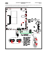
If any of the voltages shown above are out of the acceptable
range(s) shown, adjustment is required. Locate which of the
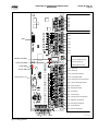
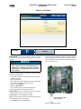
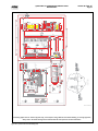
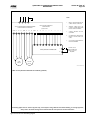
supplies require adjustment. The adjustment access hole for
each supply is located on the lower left of the front of the
supplies. If an adjustment is required, use a small insulated
Philips screwdriver, insert the tip into the access hole for the
appropriate voltage potentiometer (refer to the following
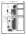
diagram for adjustment location).
090.040-M (JUNE 14)
Page 23
+5 VDC ADJUSTMENT
Locate the DC power terminal strip. Terminal 1001 is the +5
VDC, and 1000 is common (COM).Place the negative lead
on 1000, and the positive lead on 1001. Verify that the DVM
is displaying in the range of +5.10 to +5.20.
If adjustment is required, locate the adjustment access hole
on the +5 VDC supply, as previously shown. While watching
the DVM, slowly rotate the screwdriver blade clockwise to
increase the voltage or counter-clockwise to decrease until
the voltage is correctly adjusted.
+12 VDC ADJUSTMENT
Locate the DC power terminal strip. Terminal 1002 is the +12
VDC, and 1000 is common (COM). Place the negative lead
on 1000, and the positive lead on 1002. Verify that the DVM
is displaying in the range of +12.10 to +12.20.
If adjustment is required, locate the adjustment access hole
on the +12 VDC supply, as previously shown. While watching
the DVM, slowly rotate the screwdriver blade clockwise to
increase the voltage or counter-clockwise to decrease until
the voltage is correctly adjusted.
+24 VDC ADJUSTMENT
Locate the DC power terminal strip. Terminal 1004 is the +24
VDC, and 1000 is common (COM). Place the negative lead
on 1000, and the positive lead on 1004. Verify that the DVM
is displaying in the range of +24.20 to +24.50.
If adjustment is required, locate the adjustment access hole
on the +24 VDC supply, as previously shown. While watching
the DVM, slowly rotate the screwdriver blade clockwise to
increase the voltage or counter-clockwise to decrease until
the voltage is correctly adjusted.
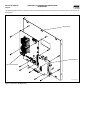
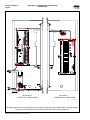
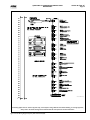
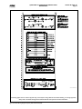
DC
Voltage
Adjust
DC
POWER SUPPLY REPLACEMENT
120 VAC
or
240 VAC
090.040-LD0004.eps
Figure 10.Power Supply Adjustment
NOTICE
Extreme care must be used when adjusting the
potentiometer. Adjustment should only be performed
by qualified personnel. The use of a non-conductive
device is recommended.
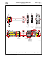
If any of the power supplies are found to be bad, or not
capable of acceptable adjustment, the failing supply will need
replacing. Refer to the Recommended Spare Parts list for the
appropriate part number.