1
Commercial Air Conditioning
SERVICE MANUAL
Models
AD96NAHAEA
AP96NACAEA
AU96NATAEA
Features
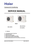
The outdoor can match with both of duct and cabinet type indoor unit
The indoor unit is identical for heat pump and cooling only unit
Infra red remote controller or wired controller
Central control and full automation, if connected with a central controller
24-hour timer (standard)
Auto-restart function
Strong energy distribution
Manual code: SYJS-001-05REV.0
Downloaded from AC-Manual.com Manuals
Edition: 2005-01-04
Commercial Air Conditioner
Model: AU96NATAEA
AD96NAHAEA, AP96NACAEA
CONTENTS
Contents………………………………………………………...2
1. Description of products & features………………………..3
2. Specification…………………………………………………5
3. Safety precaution……………………………………………10
4. Net dimension of indoor and outdoor……………………..12
5. Installation instructions………..……………………………15
6. Parts and functions…………………………………………37
7. Remote controller functions……………………………….38
8. Refrigerant diagram…………………………………………58
9. Electrical control functions………………………………….59
10. Diagnostic information (trouble shooting)……………….67
11. Electrical data………………………………………………71
12. Exploded view and parts lists…………………………….73
13. Performance curves……………………………………….81
14. Noise level charts………………………………………….85
15. Air velocity distribution…………………………………….89
2
Downloaded from AC-Manual.com Manuals
Commercial Air Conditioner
Model: AU96NATAEA
AD96NAHAEA, AP96NACAEA
1.DESCRIPTION OF PRODUCTS & FEATURES
1.1. Products code explanation
A
U 96
N
A T
A E
A
Climate type: T1 (see table 1)
Design number (A stands for design sequence, fixed
frequency
type)
Product type: A stands for heat pump type, refrigerant is R22
B stands for heat pump type, refrigerant is R407C
M stands for cool only type, refrigerant is R22
N stands for cool only type, refrigerant is R407C
Appearance character
Product series: A stands for 1 to 1
Applicable voltage: 2 stands for 220-230V/50Hz,
4 stands for 220V/60Hz,N stand for 380-400V/50Hz
Cooling / Heating capacity,96=96000BTU/h
Product type : “B” stands for cassette type, “C” stands for
convertible type, ”D” stands for duct, “S” stands for split
type, ”Q” stands for chiller system, "E" stands for ceiling
concealed type, “U” stands for outdoor unit
Air Conditioner
1.2 Brief Introduction for T1、T2、T3 working condition
Climate type
Type
of
Conditioner
Air
T1
T2
T3
Cooling Only
18 ℃~43℃
10℃~35℃
21℃~52℃
Heat pump
-7℃~43℃
-7℃~35℃
-7℃~52℃
Electricity Heating
~43℃
~35℃
~52℃
1.3 Operating Range of Air Conditioners
Temp.
Mode
Indoor
Cooling
Outdoor
Indoor
Heating
Outdoor
3
Downloaded from AC-Manual.com Manuals
Rated
Maximum
Minimum
DB
℃
27
32
15
WB
℃
19
23
14
DB
℃
35
43
-5
WB
℃
24
26
6
DB
℃
20
27
10
WB
℃
14.5
---
--
DB
℃
7
23
-10
WB
℃
6
18
---
Commercial Air Conditioner
Model: AU96NATAEA
AD96NAHAEA, AP96NACAEA
1.4 Product features
Universal outdoor unit
The outdoor unit can match with duct and cabinet type indoor unit.
High static pressure design for duct unit
The designed exterior static pressure can be adjusted from 0Pa~196Pa. The air outlet duct can be
selected freely, generally, there are two types as follow:
A:Main duct system
B:Branch duct system
Duct unit: super thin unit body, no occupying the indoor space
The whole unit can be concealed in the building, without effect of the indoor décor.
With air inlet filter, enhance the air quality
The high efficiency filter can collect the dirt and remove the bacterium, which can be installed on the
easy-to-unload place, convenient to be cleaned.
Cabinet unit: newly designed luxurious LCD operation panel
On the front panel, you can find there is a luxurious operation panel. Just slightly pressing, the
comfort will come around you. Meanwhile, the unit is equipped with the advanced large angel remote
receiving technology.
Multiple control types
or (
+
)
The duct and cabinet unit can be controlled be the wired controller or by the infrared controller. The
cabinet type unit can be controlled with the infrared controller. If the unit is duct type and you want
infrared type, you need to add an infrared controller YR-H71.
And the infrared controller can be equipped with the controller holder, convenient to fix the
remote controller.
4
Downloaded from AC-Manual.com Manuals
Commercial Air Conditioner
Model: AU96NATAEA
AD96NAHAEA, AP96NACAEA
Convenient infrared remote controller
The newly designed infrared remote controller YR-H71 can be used for all indoor units of single type,
multi split type, and H-MRV type except for the cabinet unit. This controller can be compatible with all old
remote controllers except for that of cabinet units.
Auto–restart function (optional)
All indoor units have auto-restart function. When the power supply cut off suddenly, the unit will
automatically recover the previous running mode once the power supply is on.
Self-diagnostic function
In the course of operation, if the failure occurs, the failure code will display on the wired controller or
on the operation panel. Then according to the failure code chart, you can eliminate the failure soon.
Central control function, if connected with a detector and a central
controller
24-hour timer (standard)
Changeover function
The unit can realize changeover function to enhance the reliability and the precision by connecting a
detector.
5
Downloaded from AC-Manual.com Manuals
Commercial Air Conditioner
Model: AU96NATAEA
AD96NAHAEA, AP96NACAEA
2. SPECIFICATION
PIPING
Outdoor unit
item
Function
Capacity
Capacity
Sensible heat ratio
Total power input
Max. power input
EER or COP
Dehumidifying capacity
Power cable
Signal cable
Connecting cable
Wired control cable
for wired control unit
Power source
Running /Max.Running
Start Current
Class of anti electric shock
Circuit breaker
Max. operating pressure of heat side
Max. operating pressure of cold side
Unit model (color)
Model / Manufacture
Oil model
Oil type
Compressor
Oil charging
Type
Protection type
Starting method
Type × Number
Speed
Fan
Fan motor output power
Air-flow(H-M-L)
Type / Diameter
Heat exchanger Total area
Temp. scope
External
(L×W×H)
Dimension
Package
(L×W×H)
Drainage pipe (material , I.D./O.D.)
Refrigerant control method
Defrosting
Volume of Accumulator
Noise level
Type of Four way valve
material of reduce noise
crankcase heater power
Weight
(Net / Shipping)
Type / Charge
Refrigerant
Recharge quantity
Liquid
Pipe
Gas
Connecting Method
MAX.Drop
Between I.D &O.D
MAX.Piping length
AU96NATAEA
Model
BTU/h
W
W
W
W/W
10‐³×m³/h
section
section
section
N, VAC, Hz
A/A
A
A
Mpa
Mpa
cm³
r/min
W
m³/h
mm
m²
℃
mm×mm×mm
mm×mm×mm
mm
mm/mm
L
dB(A)
W
kg / kg
g
g/m
mm
mm
m
m
cooling
92000
27000
75%
10000
13000
2.70
heating
96000
28000
/
9000
13000
3.11
10
5*6.0
1*1.5
3*2.5
3*0.5
3, 380-400, 50
cooling 18/22.8
heating16.5/22.8
36
Ⅰ-class
40
3.0
3.0
AU96NATAEA(WHITE)
JT300D-Y1L / DAIKIN
/
MINERAL
3000
scroll
inner thermal protection, 3-phase protection, pressure
direct startup
Axial × 1
/
350
10000/-/6000
TP2M / 9.52x0.35
about 1.8
cooling: 43~60 / heating: 6~7
990*760*1700
1150*925*1870
/
Capillary tube
Automatic
NO
≤65
/
XPE
34*2
161/185
R22/8500
115
12.7
28.58
flared
15
30
Norminal condition: indoor temperature (cooling): 27℃DB/19℃WB, indoor temperature (heating): 20℃DB
Outdoor temperature(cooling): 35℃DB/24℃WB, outdoor temperature(heating): 7℃DB/6℃WB
The noise level will be measured in the third octave band limited values, using a Real Time Analyser calibrated sound intensity meter. It is a sound
pressure noise level.
6
Downloaded from AC-Manual.com Manuals
Commercial Air Conditioner
item
Model: AU96NATAEA
AD96NAHAEA, AP96NACAEA
AD96NAHAEA
Model
Function
cooling
heating
Capacity
BTU/h
92000
96000
Capacity
kW
27000
28000
/
W
75%
10000
9000
13000
2.70
13000
3.11
Sensible heat ratio
Total power input
Max. power input
W
EER or COP
W/W
10‐³×m³/h
10
Signal cable
section
1*1.5
Connecting cable
section
3*2.5
N, V, Hz
1, 220-230, 50
AD96NAHAEA/grey
Dehumidifying capacity
Power source
Unit model (color)
Centrifugal×2
Type × Number
Indoor unit
r/min
1070±30/860±40/960±50
W
270
Air-flow(H-M-L)
m³/h
3600
Type / Diameter
mm
TP2M/Φ9.52
0.41
Speed(H-M-L)
Fan
Fan motor output power
Heat exchanger Total Area
m²
External
(L×W×H)
mm×mm×mm
2-7
1570*840*360
Package
(L×W×H)
mm×mm×mm
1800*980*495
mm
PVC 18/20
Temp. scope
Dimension
℃
Drainage pipe (material , I.D./O.D.)
Control type
Wired
(Remote /wired)
Fresh air hole dimension
mm
/
Electricity Heater
kW
0
Noise level
(H-M-L)
dB(A)
58/-/51
Weight
(Net / Shipping)
kg / kg
92/100
Norminal condition: indoor temperature (cooling): 27℃DB/19℃WB, indoor temperature (heating): 20℃DB
Outdoor temperature(cooling): 35℃DB/24℃WB, outdoor temperature(heating): 7℃DB/6℃WB
The noise level will be measured in the third octave band limited values, using a Real Time Analyser calibrated sound intensity meter. It is a sound
pressure noise level.
7
Downloaded from AC-Manual.com Manuals
Commercial Air Conditioner
item
Model: AU96NATAEA
AD96NAHAEA, AP96NACAEA
AP96NACAEA
Model
Function
cooling
heating
Capacity
BTU/h
92000
96000
Capacity
kW
27000
28000
Sensible heat ratio
Total power input
/
W
75%
10000
9000
Max. power input
W
13000
2.70
13000
3.11
EER or COP
W/W
10‐³×m³/h
10
Signal cable
section
1*1.5
Connecting cable
section
3*2.5
Power source
N, V, Hz
1, 220-230, 50
AP96NACAEA/ivory white
Centrifugal×2
630±30/420±40/360±50
250
4800
Dehumidifying capacity
Unit model (color)
Type × Number
Fan
Speed(H-M-L)
r/min
Fan motor output power
Indoor unit
Air-flow(H-M-L)
Type / Diameter
Heat exchanger Total Area
Temp. scope
Dimension
mm
m²
℃
External
(L×W×H)
mm×mm×mm
Package
(L×W×H)
mm×mm×mm
Drainage pipe (material , I.D./O.D.)
Control type
W
m³/h
2-7
1200*320*1850
mm
1360*510*2030
PVC 18/20
Remote
mm
/
kW
0
58/-/51
102/110
(Remote /wired)
Fresh air hole dimension
Electricity Heater
TP2M/Φ9.52
0.41
Noise level
(H-M-L)
dB(A)
Weight
(Net / Shipping)
kg / kg
Norminal condition: indoor temperature (cooling): 27℃DB/19℃WB, indoor temperature (heating): 20℃DB
Outdoor temperature(cooling): 35℃DB/24℃WB, outdoor temperature(heating): 7℃DB/6℃WB
The noise level will be measured in the third octave band limited values, using a Real Time Analyser calibrated sound intensity meter. It is a sound
pressure noise level. The detailed method please refer to the following information:
8
Downloaded from AC-Manual.com Manuals
Commercial Air Conditioner
Model: AU96NATAEA
AD96NAHAEA, AP96NACAEA
Installation state: the unit should be placed on the flat floor or be mounted in horizontal direction.
Testing method:
standing-on-floor unit: If the unit cooling
capacity is over 28000W, the noise level should
duct unit without auxiliary duct:
be measured at the front, left, right directions
respectively.
2m
duct
1m
1.4m
1m
1m
outdoor unit:
1.air outlet from side: the noise level is the average sound pressure level measured from front, left, right
directions.
2.air outlet from top: the noise level is the average sound pressure level measured from front, back, left, right
directions.
measured point:
H ( height to the ground) = (h (unit height) + 1m) /2
and, it is 1m to each side.
1m
1m
1m
h
Note: ⊙ is the real time analyser position
9
Downloaded from AC-Manual.com Manuals
Commercial Air Conditioner
Model: AU96NATAEA
AD96NAHAEA, AP96NACAEA
3. Safety precaution of indoor and outdoor
Carefully read the following information in order to operate the airconditioner correctly.
Below are listed three kinds of Safety Cautions and Suggestions.
WARNING! Incorrect operations may result in severe consequences of death or serious injuries.
CAUTION! Incorrect operations may result in injuries or machine damages; in some cases may
cause serious consequences.
INSTRUCTIONS: These information can ensure the correct operation of the machine.
Be sure to conform with the following important Safety Cautions.
The Safety Cautions should be at hand so that they can be checked at any time when needed.
If the conditioner is transferred to the new user, this manual should be as well transferred to the new user.
WARNING!
If any abnormal phenomena is found
(e. g.smell of firing), please cut off the
power supply immediately, and contact
the dealer to find out the handling
method.
Don't dismantle the outlet of the
outdoor unit.
The exposure of fan is very dangerous
whichmay harm human beings.
In such case, to continue using the
conditioner will damage the conditioner,
and may cause electrical shock or fire
hazard.
switch
off
After a long time use of air-conditioner
the base should be checked for any
damages.
If the damaged base is not repaired, the
unit may fall down and cause accidents.
10
Downloaded from AC-Manual.com Manuals
When need maintenance and repairment,
call dealer to handle it.
Incorrect maintenance and repairment
may cause water leak, electrical shock
and fire hazard.
Commercial Air Conditioner
Model: AU96NATAEA
AD96NAHAEA, AP96NACAEA
WARNING!
Installed electrical-leaking circuit
breaker.
No goods or nobody is permitted to
placed on or stand on outdoor unit.
It easily cause electrical shock without
circuit breaker.
The falling of goods and people may
cause accidents.
Air-conditioner can't be installed in
the environment with inflammable
gases because the inflammable gases
near to air-conditioner may cause fire
hazard.
Please let the dealer be responsible for
installing the conditioner.
Don't operate the air-conditioner with
damp hands.
Incorrect installation may cause water
leak, electrical shock and fire hazard.
Otherwise will be shocked.
Call the dealer to take measures to
prevent the refrigerant from leaking.
If conditioner is installed in a small
room be sure to take every measure in
order to prevent suffocation accident
even in case of refrigerant leakage.
When conditioner is deinstalled or
reinstalleddealer should be responsible
Only use correctly-typed fuse.
May not use wire or any other materials
replacing fuse, other-wise may cause
faults or fire accidents.
for them.
Incorrect installation may cause water
leaking, electrical shock and fire hazard.
Connect earthing wire.
Earthing wire should not be connected to the gas pipe, water pipe,
lightning rod or phone line, in-correct
earthing may cause shock.
Use discharge pipe correctly to ensure
efficient discharge.
Incorrect pipe use may cause water
leaking.
Earthing
11
Downloaded from AC-Manual.com Manuals
Commercial Air Conditioner
Model: AU96NATAEA
AD96NAHAEA, AP96NACAEA
4. Net dimension of indoor and outdoor
Outdoor dimension
66-
43-
33-
33-
.23-
.1-
9D<=A7 8;63
4--
61-
./-
/3
..2
./-
15
160
3/
.2-
12
Downloaded from AC-Manual.com Manuals
52
Commercial Air Conditioner
Model: AU96NATAEA
AD96NAHAEA, AP96NACAEA
Model: AD96
13
138
Air inlet
1640
1570
M5x20pcs
13
200
163
6x200=1200
35
1500
13
163
35
Control Box
Liquid pipe
60
95
25
100
80
1690
250
138
60
25
18
65
13
830
794
18
Gas pipe
12.7(1/2")
28.58(1-1/8")
M10x4pcs
Air outlet
M5x20pcs
25
510
138
13
250
80
25
49
200
45
170
13
13
530
DRAIN PIPE VP25
13
77
185
138
106
30
310
A
360
25
6X200=1200
138
60
1450
138
60
Installation dimension
Over 900
(900x1730)
Over 100
Over 300
35
Over 900
900
Check Hole
(600x600)
100
over 400
60
35
Ceiling
Over 200
(mm)
13
Downloaded from AC-Manual.com Manuals
Commercial Air Conditioner
Model: AU96NATAEA
AD96NAHAEA, AP96NACAEA
Model: AP96
A
1200
270
105
200
1148
air outlet
1000
terminal block center
50
air outlet
600
880
50
air inlet
40
813
787.5 terminal block center
1850
179
100
power terminal block
50
650
installation space
air inlet
1192.5
1222.5
15
315
4manual tap
425
200
50
50 50 50
425
82
80
8
20-50
150
100
142
view A
1828
8-
adjustment range
20-50
442
300
83 83
19
36
72
8
320
15
gas side
218
drain water
95
liquid side
272
98
277
142
78
310
(mm)
14
Downloaded from AC-Manual.com Manuals
Commercial Air Conditioner
Model: AU96NATAEA
AD96NAHAEA, AP96NACAEA
5. Installation Instructions
5.1 Outdoor installation procedure
Selection of installation site
Warning
It should be installed at places where it is firm enough to withstand the weight of the air
conditioner to prevent falling.
Typhoon and earthquake prevention. It should be installed according to specific
requirements.
Inasppropriate installation may lead to accidents.
Blow out
Installtion space
(1)During installation, connect the outdoor unit and align
Air inlet
Air inlet
the mounting surface(See the figure on the right).Mount
the electric distribution device on the external side of
Air inlet
the unit in accordance to the installation instructions for
maintenance plate
electric distribution device.
(2)To ensure good performance of the machine and faciliOver 300mm
tate installation and maintenance, adequate space must
be reserved (See figure on the right).
Over
Over 20mm
Over Over
20mm 20mm
1000mm
(front side)
Over
20mm
Note: Obstacles should be 2000mm off the top of the outdoor unit. Obstacles nearby should be 400mm lower
Rope
than the top of the unit.
Protection cushion
1. Handing
As there is no protective package for the outdoor unit,so
the following points merit attention:
(1) When forklift is used, insert the fork into the holes in
the base plate.
(2) When crane is used, lift the unit with 4 pieces of steel
rope with diameter above 6 mm.
(3) Put protective materials between the cable and the
unit to prevent deformation and damage of the surface.
Base panel
Rope
2.Mounting
(1) The distance between two connections must not be
less than 20mm.
M12 foot screw bolt
4 screws each unit
15
Downloaded from AC-Manual.com Manuals
Refer to the following figure for the distance between the
foundation bolts.
(2)When the refrigerant pipe is connected from the bottom of
the unit,the unit should be raised at least 500mm(see the
figure below)
(3)In snowy regions,snow-proof facilities should be used(see
the figure below).
(Poor snow-proof facilities may lead to damge.To avoid
inconveniences,the unit should be raised and snow-proof
covers should be installed at the air inlet and outlet.)
Model: AU96NATAEA
AD96NAHAEA, AP96NACAEA
1100
Through hole*15x20*
Above 500mm
Commercial Air Conditioner
Refrigerant tube
Air inlet snow-proof cover
Air outlet snowproof cover
(4)During installation,anti-vibration rubber pads should be used
between the machine and the bracket.
Air inlet snowproof cover
3.Connection of refrigerant pipe
Warning
During installation,if refrigerant leakage occurs,ventilation measures must be taken.When
refrigerant meets with fire,hazadous gas will be produced.
After installation,make sure that there is no refrigerant leakage.
Refrigerant,if meeting with heaters and stoves,ect in the room,may produce hazardous gas.
Connection of refrigerant pipe
(1) The joints of the refrigerant pipe are inside the unit.Take off the access hole cover in front of
the unit.
(2) The pipe can be connected from the front or bottom of the outdoor unit.
(3) Remove the L-shaped pipe from the valve by welding and connect the accessory pipe to the
valve.
(4) In the case of front connection,cut the accessory pipe at the height of the fixing panel.Then
join the pipe with an elbow and let it go through the fixing panel.For the convenience of maintenance,
bend the pipe down (once) and then connect pipe to the right or left.
(5) In the case of bottom connection,join the pipe with accessory pipe through the holes in the
base plate of the outdoor unit,and connect pipe the left or right or the back.
Tube fixing
panel
Bottom plate
Tub
e
to th
M6
M4
e ba
Access hole cover
ck
to
Tube
ht
the tig
to
Tube
16
to
Tube
ft
the le
Downloaded from AC-Manual.com Manuals
to
Tube
ft
the le
ht
the tig
Commercial Air Conditioner
Model: AU96NATAEA
AD96NAHAEA, AP96NACAEA
(6) During welding,the gas pipe valve must be cooled down with a wet cotton cloth.
During welding of the distribution pipe
1.In case of brazing weld of joint,nitrogen must be filled in the pipe to prevent oxidization.
2.The refrigerant pipe should be newly-made and clean.During installation,do not let water and other
substance into the pipe.
3.Use two spanners to tighten the connecting nut.One spanner will make loose connection.
The torque moment should conform to the specified value.(Refer to the below)
Tube diameter
Torque moment for
Torque moment for
(mm)
pre-installation (N.m)
tightening up (N.m)
12.70
49.0(5.0kgf m)
53.9(5.5kgf m)
Selection of tube material and size
Determinaltion of tube diameter (Refer to the diagram on next page for steps 1,2,3,4 and 5 below)
1.Tube between the outdoor unit and the first bypass(main tube):
The diameter of the main tube and the outdoor tube should be the same.
2. Tube between bypasses(sub-tube):
The diameter of the sub-pipe is determined according to the total capacity of all the connected
indoor units.But if it is larger than the capacity of the outdoor unit,the diameter should be determined
according the capacity of the outdoor unit.
Install the nonreturn loop and oil trap
2.Outdoor is higher
1.Outdoor is lower
liquid nonreturn loop
Outdoor
Indoor
Oil trap (one per
6m)
Outdoor
17
Downloaded from AC-Manual.com Manuals
Indoor
Commercial Air Conditioner
Model: AU96NATAEA
AD96NAHAEA, AP96NACAEA
Crucial points:
When testing, never use oxygen,flamable and poisonous gases.
Step 1:Charge for more than 3 minutes under 0.3MPa(3.0kg/cm2g)
Step 2:Charge for more than 3 minutes under 1.5MPa(15kg/cm2g)
--Serious leakage may be found.
Step 3:Charge for more than 24 hours under 3.0MPa(3.0kg/cm2g)
--Small leakage may be found.
Check for pressure decrease
Without pressure decrease-Pass
With pressure decrease-Check for leaage.There will be a 0.01MPa(0.1kg/cm2g) pressure change
for every 1 C ambient temperature change during the 24-hour pressure charge.It should be
corrected during the test.
Low-pressure High-pressure
gauge
gauge
Tightly
closed
Tightly
closed
Outdoor
Solder joint Solder joint
Solder joint
Tightly
closed
Indoor unit
Access hole
Access hole
VL VH
6.4
Copper
pipe
Relief valve
6.4
Copper pipe
Outdoor unit
Three-way valve fully closed liquid side
Detailed diagram of the
three-way valve
(Gas side )access hole
To the gauge
(Gas side)three-way valve
distributor
(Liquid side)access hole
To the unit
To the unit
(Liquid side)three-way valve
Field tube Field tube
installation installation
18
Downloaded from AC-Manual.com Manuals
Gauge distributor
Nitrogen bottle
Indoor
Three-way valve fully
closed(gas side)
Commercial Air Conditioner
Model: AU96NATAEA
AD96NAHAEA, AP96NACAEA
Check for leakage
In the case of pressure decrease during steps 1 to 3 ,check the joints with the ear,hand or soapsuds for
leakage.Repair it by welding or tighten the connecting nut up.
Vacuum Pumping
Use vacuum pump to evacuate the air.Never use the refrigerant for the evacuation.
Drain off the nitrogen gas after the leak test and then connect the vacuum pump as shown in the figure
below.
The vacuum pumping must be done from both the liquid and gas inlets.
Low-pressure High-pressure
gauge
gauge
Indoor
Tightly
closed
Three-way valve fully
closed(gas side)
Outdoor
Solder jointSolder joint
Gauge distributor
6.4Copper
pipe
Access hole
P
Tightly
closed
Tightly
Solder joint closed
Indoor unit
Access hole
Vacuum pump
Outdoor unit
Three-way valve fully closed
liquid side
Detailed diagram of the
three-way valve
(Gas side )access hole
To the gauge
(Gas side)three-way valve
distributor
To the unit
To the unit
(Liquid side)access hole
(Liquid side)three-way valve
Field tube Field tube
installation installation
Use a vacuum pump with high degree of vacuum(below-755mmHg) and large volume displacement
(above 40L/min)
The pumping time depends on the length of the connecting pipe.Generally,it takes about 2-3 hours.
Make sure that the Y-shaped valves on both the gas and liquid sides are closed before pumping.
If the vacuum can no reach-755mmHg within 2 hours,continue pumping for another 1 hour.
If the vacuum can no reach-755mmHg after more than 2 hour's pumping,close the valves VL and
VH on the gauge distributor and stop pumping.One hour later,check the vacuum again.If the
vacuum has changed,it means there is a leakage.Repair it.
After the above steps,replace the vacuum pump with the refrigerant pump and refill refrigerant.
Charging refrigerant
Refrigrant must be charged in liquid state.
Refrigerant bottle with or without a siphon
tube can be refilled with refrigerant upright
or upside down,Respectively.
19
Downloaded from AC-Manual.com Manuals
Containers for R22
refrigerant must be
marked with R22
and a brown Stripe.
R407C refrigerant cannot share the same
instrument distributor and filling pipes.
Commercial Air Conditioner
Model: AU96NATAEA
AD96NAHAEA, AP96NACAEA
Refilling of refrigerant
After the vacuum pumping,replace the vacuum pump with the refrigerant pump and refill refrigerant.
Calculation of refrigerant quantity
The factory filled refrigerant into the piping excludes the part of pipes according to be refilled on the site.
Refill the amount of refrigerant into the piping according to the following formula.
The factory filled refrigerant is listed in the table below:
The quantity of the refrigerant to be refilled during installation depends on the diameter and length
of the liquid piping.
The quantity of the refrigerant t be refilled on the site=Actual length of liquid tube x quantity of
refrigerant to be refilled for per meter of liquid pipe.
Recharge refrigerant
When the outdoor valve is shut,fill the refrigerant from the access hole at the gas and liquid sides.
If the required filling is impossible,open all the gas and liquid valves,then slightly shut the gas
valve, run the compressor and fill the refrigerant from the access hole at the gas side.Now adjust
the gas valve to control the refrigerant flow,which will be gasified during absorption by the system.
If there is insufficient refrigerant in the system caused by leaks,refill it after the remaining refrigerant
is recollected.
Open all valves
Open all the valves of the outdoor unit.
Heat isolation of the pipes
Separate isolation should be made for the liquid and gas pipes.
Materials used for the pipe isolation at the gas side must withstand above 120 C temperature.
For AU96NATAEA:
Charging refrigerant (R22): Before charging refrigerant, the pressure in the system
must be kept at least for 15 minutes under 130Pa, and the pressure will not go up
within 30 minutes, only in this case, the refrigerant can be filled.
When the connection pipe is less than 5 meters, additional refrigerant needs not be
charged. Once the connection jpipe is more than 5 meters, please recharge the
refrigerant as the following formula:
Refrigerant quantity=(lenth of connection pipe-5m)*115g
Detailed procedures:
a.Cut off the vacuum pump pipe to prepare charging refrigerant
b.Place the R22 container on the scales, switch off the low pressre valve of the
pressure pipe to make the liquid type refrigerant enter the system from the high
pressure side.
c.If the system pressure goes up, stop charging refrigerant and when the
refrigerant quantity arrives the rated value, switch off the high pressure valve,
then place the R22 container on the scales with the jaw to up. Open the low pressure
valve to start up the unit, at this time, the refrigerant is gas state.
When the charged refrigerant arrives the rated value, after confirming the refrigerant
quantity is proper, unload the flexible joint and install the copper nut of the connector.
20
Downloaded from AC-Manual.com Manuals
Commercial Air Conditioner
Model: AU96NATAEA
AD96NAHAEA, AP96NACAEA
Electric wiring
Note:
All the wires should be copper core wires.
The power cable of indoor unit should be equipped according to the operation manual indoor unit.
When connecting the indoor & outdoor wire, check the number of the indoor & outdoor terminals,
the terminals with the same number connected together with one wire.
Incorrect wiring will damage the controller of the air conditioner or make the unit work abnormally.
The air conditioner must use special power circuit and special air switch (40A), groundign wire.
The wiring work should be done by a qualified electrician according to the national wiring rule.
The creepage breaker must be installed. The grounding line and the neutral line of the receptacle
must be strictly separated. It is incorrect to connect the neutral line with the grounding line.
The connection type of power cord is Y connection. If the soft power cord is damaged, to avoid
risk, it must be replaced by the manufacturer or their specific repair department or similar professional
worker.
Wiring method
1.The wiring method of orbicular terminal
For the connection wire which end is orbicularterminal,
its wiring method is as the right figure shown.
Dismantle the screw and put it through the ring at
the end of the connection wire, then connect it to
the terminal block and tighten the screw.
The wiring method of orbicular terminal
2.The wiring method of straight terminal For those
Wrong pressing
connection wires whose end are not orbicular terminals, Correct pressing
Terminal block
their wiring method is: Loosen the connecting screw,
insert the end of the wire directly into the terminal block,
and then tighten screw. Pull the wire outwards slightly to
Wire holding clamp
confirm it is held tightly.
3.Pressing method of connection wire:
After wiring, the connection wire must be pressed with wire
holding clamp. The wire holding clamp should press on the
out cover of the connection wire. As the right figure shown:
Connect wire between indoor & outdoor unit
As the wiring diagram show to arrange the connection
wire.
Note: The terminal blocks mark at the two ends of the
connection wire should be corresponding one by one,
otherwise the air conditioner cannot work normally.
(Sketch map)
Terminal block of
indoor unit
1
2
3
1
2
3
Y/G
L1 L2 L3 N
Terminal block of
outdoor unit
Power supply:
3N,380-400V,50Hz
Power terminal
block of outdoor
unit
Others
1. Power supply
The parameter of power cord is over 2.5mm .
Air conditioner must use an exclusive line (over 30A)
When installation air conditioner in a wet place, try to use a circuit breaker against
Current leakage.
For installation in other places, use circuit breaker as far as possible.
21
Downloaded from AC-Manual.com Manuals
Commercial Air Conditioner
Model: AU96NATAEA
AD96NAHAEA, AP96NACAEA
The breaker of the air conditioner should be all-pole switch ; and the distance between
its two contacts should be no less 3 mm.
Such means for disconnection must be incorporation in the fixed wiring
2. Pipe cutting and flaring
Be sure to carry out deburring after pipe cutting with a pipe cutter.
Insert flaring tool to make a flare.
A
Pipe dia.
Flaring tool
Liquid pipe
Correct
12.7mm (1/2")
Dimension A(mm)
1.2 ~ 2.0
Incorrect
Lean Damaged flare Crack
Partial Too outside
Installation inspection and test run:
Please operate unit according to this Manual.
Items to be checked during test run. Please made a " "in " "
Are there any gas leakage?
How is insulation at piping connection carried out?
Are electric wires of indoor and outdoor unit firmly inserted into terminal block?
Is electric wiring of indoor and outdoor securely fixed?
Is draminage securely carried out?
Is earth line ( grounding ) securely connected?
Is power supply voltage abided by the code?
Is there any noise?
Is control display normal?
Is cooling operation normal?
Is room temp. regulator normal?
3.Calculation of refrigerant density
Calculation will be made according to the following methods:
1) Total refrigerant content of each system (kg) =content of 1 outdoor system + refilled refrigerant
Content of 1 outdoor system:Factory filled refrigerant
Refilled refrigerant:Filled content during installation according to the diameter and length of the
liquid piping.
2) Calculation of the minimum room sapce (m3).
3) Calculation of refrigerant density
Total refrigerant content
Refrigerant density:0.3(kg/m3)
Minimum room space
22
Downloaded from AC-Manual.com Manuals
Commercial Air Conditioner
Model: AU96NATAEA
AD96NAHAEA, AP96NACAEA
2.Preventive measures against excess of critical value
1) Make ventilation holes
Ventilation holes should be built above and under the door.The area of each hole should not be
smaller than 0.15% of the room space.Holes can be made directly in the wall.
2) Reduce the filling content of refrigerant
Filling content of refrigerant can be reduced by shortening the distance between the indoor and
outdoor units.
By reducing the capacity of the outdoor unit.
When outdoor unit be made up of several units.the outdoor capacity of each system should
reduce.Sothe refrigerant content of system reduce.
3) Install ventilation fans.
Users can install uninterrupted ventilation fans to keep the refrigerant density under the critical
value.
If uninterrupted ventilation is impossible,a combined fanning and alarming device should be
installed in its stead (through which immediate ventilation is possible when leak occurs).
(See the figure below)
An example
Ventilation fan and gas leak alariming device
The gas leak alarming Vertilation opening
device should be installed
at refrigerant gas
stagnation areas
23
Downloaded from AC-Manual.com Manuals
Commercial Air Conditioner
Model: AU96NATAEA
AD96NAHAEA, AP96NACAEA
Installation instruction
Notice
This manual can not include all kinds of conditions, if you have new
requirements and questions, please contact with local Haier Sales Center.
Warning
Before installing the unit, please read this manual carefully. Improper
installation may cause accidents and make unit damage or death.
Installation tools
1. Screw driver
3. 70mm dia. hole core drill
5. Spanner (14, 17, 27mm)
7. Flaring tool
9. Nipper
11. Measuring tape
13. Refrigerant oil
2. Hacksaw
4. Spanner (dia. 17, 27mm)
6. Pipe cutter
8. Knife
10. Gas leakage detector or soap water
12. Reamer
14. Lead-solder tool
Standard accessories
Following parts shall be field supplied
Parts in the following list are
accessories for the unit installation
which can be used if necessary.
No.
Mark
Parts name
A
Adhesive tape
B
Pipe clip
C
Connecting hose
D
Drain hose
3
E
Insulation material
4
F
Putty
5
1
Downloaded from AC-Manual.com Manuals
1
Fall-prevention fitting metal
2
Self-tapping scerw
5
2
Wooden bolt
Wall hole cover
2
1
Piping hole cover
6
24
Shape and description QTY
L-shaped metal
2
Commercial Air Conditioner
Model: AU96NATAEA
AD96NAHAEA, AP96NACAEA
Installation procedure
1. Before installation
[Before finishing installation, do not throw the attached installation parts away.]
Confirm the route to carry the units to the installation place.
Do not remove the package of the unit, before carrying it to the installation place.
When have to remove the package, use a soft material or protection board with rope to lift
the unit to prevent the unit from damage or bumping scrape.
2. Selection of installation place
Select the firm place that will not influenced by vibration and can bear the weight of the
unit
Select the place with easy drainage and place can perform outdoor unit pipe connecting.
Select the place far away from heat source, vapor source and direct sunshine to avoid
the causing of the trouble in operation parts and the deformation of the casing.
Select the place where the cool air or warm air can evenly spread to every corner of the
room.
Select the place near power receptacle leaving sufficient space around the unit. (Referring
to installation diagram)
Avoid the following installation places
Place with oil fog splash and much vapor (e.g. mechanical plant and kitchen, etc.) to prevent
heat exchanger from performance lowering and plastic parts from corroding to damage.
Place may generate or keep corrosive gas (sulfur dioxide, etc.), flammable gas (diluent,
gasoline, etc.) to prevent heat exchanger from corroding, plastic parts from damage and
flammable gas from causing fire accident.
Hospital, etc. places near the machine generates electromagnetic wave or high frequency
signal to prevent the mixed wave from causing wrong action of the control parts.
Place can be blown by the sea wind (coastal area) to prevent the casing and heat exchanger
from corroding.
(Indoor unit) please keep the spaces larger than the following dimension.
3. Installation space
600
50
Unit (mm)
1000
50
600
50
600
25
Downloaded from AC-Manual.com Manuals
Commercial Air Conditioner
Model: AU96NATAEA
AD96NAHAEA, AP96NACAEA
Installation of indoor unit
Selection of installation place
Place where it is easy to route drainage pipe and outdoor piping.
Place away from heat source and with less direct sunlight.
Place where cool and warm air could be delivered evenly to every corner of the room.
Place near power supply socket. Leave enough space around the unit (refer to installation
drawings).
Fixing of the unit
1. Position of the wall hole
Wall hole should be decided according to installtion place and piping direction. (refer
to installation drawings)
2. Making a wall hole
Drill a hole of 70mm dia. with a little slope towards outside.
Install piping hole cover and seal it with putty after installation.
INDOOR
OUTDOOR UNIT
wall hole
wall thinkness
70mm
( Cross section of wall hole )
Fixing of indoor unit
To prevent it from fall off, please fix the unit with fall-prevention fitting at wall and Lshaped metal at floor.
Self-tapping
screw
all-prevention fitting metal (accessory)
Wood screw
L-shaped metal
(accessory)
Please install the whole unit
horizontally,with a slop of 1
degree at front and rear,left
and right.
Installation of fall-prevention fitting metal:
Fix the fitting metal to the wall by screws so that there is no clearance between them.
With the unit set up vertically, fix the fitting metal to the unit with screws while making an adjustment
at the long portion of the hole so that there is no clearance between the upper surface and the
fitting metal.
26
Downloaded from AC-Manual.com Manuals
Commercial Air Conditioner
Model: AU96NATAEA
AD96NAHAEA, AP96NACAEA
Installation of L-shaped metal
Fix to the unit by screws so that there is no clearance between the fitting metal and the unit.
After confirming that the unit has been set up vertically to the floor, fix it to the floor by bolt.
Piping connection
1. Connecting method
Apply refrigerant oil at half union and flare nut.
To bend a pipe, give the roundness as large as possible not to crash the pipe.
When connecting pipe, hold the pipe centre to centre then screw nut on by hand,refer to Fig.
Be careful not to let sundries, such as sands enter the pipe.
Forced fastening without centering may
damage the threads and cause a gas leakage.
Pipe diameter
Liquid pipe 12.7mm(3/8")
Fastening torque
42N.m
2. Piping connection of indoor unit
Arrangement of piping and drainage pipe
After opening inlet grill, you will see a control box as shown in the Fig.
Remove the cover before working.
Cut away, with a hammer or a saw, the lid for piping according to piping direction.
27
Downloaded from AC-Manual.com Manuals
Commercial Air Conditioner
Insulation material
Model: AU96NATAEA
AD96NAHAEA, AP96NACAEA
Drain hose
Connecting electric cable
for indoor and outdoor unit
Copper tube
According to the piping method, connect the piping on indoor unit with union of connecting pipe.
Arrange the piping as per the wall hole and bind drain hose connecting electric cable and piping
together with polyethylene tape.
Insert the bound piping connecting electric cable and drain hose through wall hole to connect
with outdoor unit.
Arrangement of drain hose
Drain hose shall be placed in under place.
There should be a slope when arrange drain hose. Avoid up and down waves in drain hose.
Indoor unit
Up
Down
Bad
Good
If humidity is high, drain pipe( especially in room and indoor unit ) must be covered with insulation
material.
Main points of installation refrigerant pipe
Slope
Please install the gas pipe and liquid pipe according to the following shown method.
Please remove the cover piece on the gas pipe and the screw cap on the liquid pipe.
A
B
2 Please connect the connecting pipes between indoor and outdoor unit according to the
following method.
a) When introducing the pipe from right side
Use attached accessory <A> to connect the on-the-spot connecting pipe and gas
pipe.
A
28
Downloaded from AC-Manual.com Manuals
B
Commercial Air Conditioner
Model: AU96NATAEA
AD96NAHAEA, AP96NACAEA
b) When introducing pipe from rear side or left side
Use attached accessory <A> to connect the on-the-spot connecting pipe
and gas pipe.
3 After finishing connection of connecting pipe, please do thermal insulation treatment
by using the attached thermal insulation material. Otherwise, it may cause water
leakage.
Setting of wire controller dial switch
Setting of this series of air conditioner dial switch: 1, ON; 2, ON.
29
Downloaded from AC-Manual.com Manuals
Commercial Air Conditioner
Model: AU96NATAEA
AD96NAHAEA, AP96NACAEA
Indoor installation instruction
NOTICE
All Wiring of this installation must comply with NATIONAL, STATE AND LOCAL
REGULATIONS. These instructions do not cover all variations for every kind of
installation circumstance. Should further information be desired or should particular
WARNING
BE SURE TO READ THESE INSTRUCTIONS CAREFULLY BEFORE BEGINNING
INSTALLATION. FAI-LURE TO FOLLOW THESE INSTRUCTIONS COULD
1. Before installation [Before finishing installation, do not throw the attached parts installation needs]
Confirm the way to move the unit to the installation place.
Before moving the unit to the installation place, do not remove their packages.
When have to remove the package, use a soft material or protection board with rope to lift the unit assembly to avoid
unit damage or bumping a scrape.
2. Select installation place
(1) The chosen installation place should meet the following requirements and get the users consent.
Place ensures ideal airflow distribution.
The passage of airflow has no obstacles.
When importing outside air, it should be imported directly from outdoors. (if the pipe can not be extended, it also can
not be imported from top)
Place ensures enough space for maintenance.
The pipe length between indoor and outdoor unit is in the permitted limit (referring to outdoor unit installation part).
The indoor unit, outdoor unit, electric wire and connection wire is at least 1m away from television
and radio. This is to avoid the image disturbance and noise caused by the above-mentioned home appliance. (Even
if 1m away, if the electromagnetic wave is too strong, it can also cause noise.)
(2) The height of ceiling
The indoor unit can install on the ceiling, which height is no more than 3m.
(3) Install and use the hoisting screw. Check if the installation place can bear the weight of unit assembly.
If not certain, strengthen it before install the unit.
Over 300
Air out
Over 900
Checking meatus
(600x600)
Over 200
Over 100
Air in
Ceiling
3. Preparation before installation
(1) The position relation among hoisting screw (unit: mm)
890
360
600
Up side
750
794
250
Down side
30
Downloaded from AC-Manual.com Manuals
Commercial Air Conditioner
Model: AU96NATAEA
AD96NAHAEA, AP96NACAEA
(2) If necessary, cut the opening installation and checking needed on the ceiling. (If has ceiling)
Before installation, finish the preparation work of all the pipes (refrigerant, drainage) and wire
(wire controller connection wire, indoor and outdoor unit connection wire) of indoor unit, so that
after installation, they can be immediately connected with outdoor unit.
Cut the opening on the ceiling. Maybe it needs to strengthen the ceiling to keep the ceiling even
and flat and prevent the ceiling from vibration. For details, please consult to the builder.
(3) Suspending bolts installation
Use care of the piping direction when the unit is
(Use M10 screw bolt)
Built-in anchor
In order to bear the weight of the unit, for
Insert
Built-in plug
existed ceiling, using foundation screw bolt,
for new ceiling,using burying embedded
screw bolt, burying screw bolt or spot
supplied other parts.
Concrete
Before going on installation, adjust the gaps
with ceiling.
suspending bolt M10
4. Installation of indoor unit
Hanging bolt
Fix the indoor unit to the hanger bolts.
M10
nut
M10 washer
If required, it is possible to suspend the unit to
the beam, etc.
Main unit
Note
M10 spring washer
When the dimensions of main unit and ceiling holes does not match, it can be
adjusted with the slot holes of hanging bracket.
Adjusting to the levelness
(a) Adjust the out-of levelness using a level or by the following method.
Make adjustment so that the relation between the lower surface of the unit proper and water level in the
hose becomes as given below.
Piping side
Supply water
Water level
0~5 mm
(0~0.2")
PVC hose
Piping side
Supply water
Water level
0~5 mm
PVC hose
(0~0.2")
Bring the piping side slightly lower.
(b) Unless the adjustment to the levelness is made properly, malfunctioning or failure of the float switch may occur.
5. Drain Piping
(a) Drain piping should always be in a downhill grade (1/50~1/100) and avoid riding across an elevation or making traps.
Good piping
Improper piping
Avoid riding across an elevation
Suspension
1.5m ~ 2m
bolts
Air vent
Keep free from traps
Do not pipe under water
Heat
A downhill grade
insulation of 1/100 or more
31
Downloaded from AC-Manual.com Manuals
Commercial Air Conditioner
Model: AU96NATAEA
AD96NAHAEA, AP96NACAEA
(b) When connecting the drain pipe to unit, pay suffcient attention not to apply excess force to the piping on the unit side.
Also, fix the piping at a point as close as possible to the unit.
(c) For drain pipe, use hard PVC general purpose pipe VP-25(I.D.1") which can be purchased locally. When connecting,
insert a PVC pipe end securely into the drain socket before tightening securely using the attached drain hose and clamp.
Adhesive must not be used connection of the drain socket and drain hose (accessory).
Stage
difference Drain hose
Drain socket part
Drain socket
Main unit
VP 25 joint
Pipe cover(large) (field purchased)
[for insulation]
(accessory)
Drain hose
Clamp (accessory)
(accessory)
Adhesion
Pipe cover(small)
[for insulation]
(accessory)
(d) When constructing drain piping for several units,
position the common pipe about 100 mm below
the drain outlet of each unit as shown in the sketch.
Use VP-30(11/4") or thicker pipe for this purpose.
(e) The stiff PVC pipe put indoor side should be
heat insulated.
VP 25
(field purchased)
Pipe cover
[for insulation]
(field purchased)
Secure the elevation as high as possible
(approx. 100 mm)
A downhill grade of
1/100 or more
VP 30
(f) Avoid putting the outlet of drain hose in the places with irritant gas generated. Do not insert the drain hose directly into
drainage,where the gas with sulfur may be generated.
(g) Backwater bend
Because the drain spout is at the position, which negative pressure may occur. So with the rise of water level in the
drain pan, water leakage may occur. In order to prevent water leakage, we designed a backwater bend.
H2 H1
The structure of backwater bend should be able to be cleaned. As the below figure shown, use T type joint.The backwater
bend is set near the air conditioner.
As figure shown, set a backwater bend in the middle of drain hose.
H1=100mm or the static pressure of air sending motor
H2=1/2H1 (or between 50~100mm)
Drainage Test
Conduct a drainage test after completion of the electrical work.
During the trial, make sure that drain flows properly through the piping and that no water leaks from connections.
3 In case of a new building, conduct the test before it is furnished with the ceiling.
4 Be sure to conduct this test even when the unit is installed in the heating season.
1
2
Procedures
1
2
Supply about 1000 cc of water to the unit through the air outlet using a feed water pump.
Check the drain while cooling operation.
6. Installation of air suction and discharging duct
Please consult the after-sales service worker of Haier Air Conditioner for the choosing and installation
of suction inlet, suction duct, discharging outlet and discharging duct. Calculating the design drawing
and outer static pressure, and choose the discharging duct with proper length and shape.
32
Downloaded from AC-Manual.com Manuals
Commercial Air Conditioner
Model: AU96NATAEA
AD96NAHAEA, AP96NACAEA
muffler cavity (air sending)
Enlarging chart of
profile chart A
Sacking joint
Insulation
A
Air conditioner
main unit
Air outlet
Vibration resistance hook
Air volume adjuster
Checking meatus
Ceiling
Air suction grille with air filter
The length difference among every duct is limited below 2:1.
Reduce the length of duct as possible as can.
Reduce the amount of bend as possible as can.
Use heat insulation material to bind and seal the part connecting main unit and the flare part of air
discharging duct. Perform duct installation work, before the fitment of ceiling.
Bad example
Bad example
Good example
7. Calculation method of the dimension of the simple quadrate air duct
Presuming the unit length friction impedance of the duct is 1Pa/m, when the dimension of one side of
the air duct is fixed as 250mm, as shown below:
Air volume Duct(mmxmm) Air volume Duct(mmxmm)
A
Air conditioner
A
B
B
A
A
Static pressure box
2400m3/h
250x560
(40m3/min)
3
600m /h
250x190
(10m3/min)
1200m3/h
250x310
(20m3/min)
300m3/h
(5m3/min) 250x120
AD42NAHAAA
AU42NAQAAA
(HDU-42H03/H)
AD242AHAAA
AU242AOAAA
(HDU-24H03/H)
Equipped with
air filter (bought)
The calculation of duct resistance (the simple calculation is as follow table)
Straight part
Calculate as per 1m length 1Pa, 1Pa/m
Bend part
Each bend takes as a3~4m long straight duct
Air out part
Calculate as 25Pa
Static pressure box
Calculate as 50Pa/each
Air inlet grille (with air filter) Calculate as 40Pa/each
33
Downloaded from AC-Manual.com Manuals
Commercial Air Conditioner
Model: AU96NATAEA
AD96NAHAEA, AP96NACAEA
The chosen chart of simple duct
Shape
Item
Air volume
3
3
m /h(m /n)
100
200
300
400
500
600(10)
800
1,000
1,200(20)
1,400
1,600
Shape
Square duct
Item
Air volume
Dimension
3
(mmxmm)
250
250
250
250
250
250
250
250
250
250
250
x
x
x
x
x
x
x
x
x
x
x
3
m /h(m /n)
60
90
120
140
170
190
230
270
310
350
390
1,800(30)
2000
2400
3,000(50)
3,500
4,000
4,500
5,000
5,500
6,000(100)
Square duct
Dimension
(mmxmm)
250
250
250
250
250
250
250
250
250
250
x
x
x
x
x
x
x
x
x
x
430
470
560
650
740
830
920
1000
1090
1180
8. The attentive matters in installation of air suction and discharging duct
Recommend to use anti-frost and sound-absorbing duct. (locally bought)
The duct installation work should be finished before the fitment of ceiling.
The duct must be heat insulated.
The specific air-discharging outlet should be installed at the place where the airflow can be reasonably distributed.
The surface should leave a checking meatus for checking and maintenance.
Special air discharging outlet
Use screw bolt to fix
Duct
Air
Air
9. The examples of improper installation
Do not use air in duct and take the ceiling inner side instead. The result is because of the irregular outer air mass,
strong wind and sunshine, the humidity is increased.
There may be water drop on the outside of duct. For cement and other new constructions, even if not taking ceiling
inner side as duct, the humidity will also be so high. At this time, use glass fiber to perform heat preservation to the
whole. (use iron net to bind the glass fiber)
Maybe exceeding the unit operation limit (for example: when indoor dry bulb temperature is 35 C, wet bulb temperature
24 C), it may lead to overload of compressor.
Affected by the capacity of air discharging fan, the strong wind in the outer duct and wind direction,when unit air sending
volume exceeds the limit, the discharged water of heat exchanger will overflow, leading to water leakage.
Air discharging fan
34
Improper example
Downloaded from AC-Manual.com Manuals
Commercial Air Conditioner
Model: AU96NATAEA
AD96NAHAEA, AP96NACAEA
10. The operation method of fan controller
Through the fan controller switch in the electric box, the air volume of this unit can be continuously adjusted.
It is unnecessary to adjust air volume through the duct side wind level (unit outside static adjustment).
The air volume set should be in the operation air volume range.
Figure I shows the position of fan controller in the electric box and operation method.
After finishing the electric work, perform test run. According to the main points in Figure II making the chosen switch No.
accordant. And confirm if it reaches the needed air volume.
Note:
1) When operating the fan controller, it is possible to touch the electric charging part, so do cut off the power supply.
2) Do not set the dial at the position less than 1.
3) The figure circled in Figure II indicate the capacity number of fan controller. The non-listed capacity number may exceed
the permitted operation capacity range, so it is impossible to operate.
4) When delivering from factory, the capacity number of fan controller is set at No.5.
Rotate this switch
Condition of standard air volume
(air volume 100Pa)
High
Low
(capacity number
setting:
No. 1 ~ No. 8)
200
¢ ¢
¢
¢
¢
Outer static pressure Pa
¢
Once the fan controller
has trouble, this linker
can perform emergency
assistant control. When
this linker is connected
to the linker from the
PCB, it can operate with
total load.
¢
150
¢
¢
¢
¢
100
¢
50
0
When this linker is
connected to the linker
from the PCB, through
the fan speed adjustment
panel to adjust speed.
26
30
Lower limit
Figure 1
Example of
duct
¢ ¢
3435
40
43
Upper limit
Standard air volume(m3/min)
Figure 2
The example of the method of choosing capacity number:
3
1) If the unit is in high-speed operation, needing take outer static pressure is 180Pa in capacity air volume 34m /min as working condition
point, according to Figure II The characteristic chart of air volume, the capacity numberof fan controller is No. 2.
3
2) If the unit is in low speed operation, needing take outer static pressure is 60Pa in capacity air volume 32m /min as working condition
point, according to Figure II The characteristic chart of air volume, the capacity number of fan controller is No. 4.
11. Refrigerant pipe
[The air side pipe, liquid side pipe must be faithfully heat insulated, if no heat insulation, it may cause water leakage.]
The outdoor unit has been charged with refrigerant.
When connect the pipe to the unit or dismantling the pipe from the unit, please follow the figure shown,use spanner
and torque spanner together.
When connect cone nut, the inner side and outside of cone nut should paste with refrigerant oil. Use hand to twist 3-4
rings, then fasten with spanner.
Referring to Table I to confirm the fasten torque. (too tight may damage nut leading to leakage)
Check if the connection pipe leaks, then do heat insulation treatment, as below figure shown.
Only use seal cushion to bind the joint part of air pipe and heat insulation parts.
Paste the refrigerant oil here
Torque spanner
Spanner
35
Pipe joint
Cone nut
Downloaded from AC-Manual.com Manuals
Middle size seal cushion (accessory)
(Use seal cushion to
bind the pipe joint)
Clamp
Heat insulation (accessory)
(for liquid pipe)
Heat insulation (accessory)
(for gas pipe)
Gas pipe
Liquid pipe
Commercial Air Conditioner
Liquid pipe
80
510
Gas pipe
Electric box
Upper
310
Air inlet
Down side
530
Specification of pipe Tighten torque
Cone dimension
A (mm)
(mm)
Cone
45
50N.m
Air outlet
30
Drain hose connection mouth
VP25 PVC pipe
12.70
Model: AU96NATAEA
AD96NAHAEA, AP96NACAEA
90
1.2~2.0
2
R0.4~0.8
0.5
A
Electric wiring
WARNING
DANGER OF BODILY INJURY OR DEATH
TURN OFF ELECTRIC POWER AT CIRCUIT BREAKER OR POWER SOURCE BEFORE
MAKING ANY ELECTRIC CONNECTIONS. GROUND CONNECTIONS MUST BE
COMPLETED BEFORE MAKING LINE VOLTAGE CONNECTIONS.
(1) Selection of size of power supply and interconnecting wires.
Precautions for Electric wiring
Electric wiring work should be conducted only by authorized personnel.
Do not connect more than three wires to the terminal block. Always use round type crimped terminal lugs with
insulated grip on the ends of the wires.
Use copper conductor only.
Select wire sizes and circuit protection from table below. (This table shows 20 m length wires with less than 2%
voltage drop.)
Circuit breaker
Item
Model
Phase Switch breaker
(A)
3
Overcurrent
protector
Earth leakage breaker
Power
source wire
Leak
Switch
size
curren
break
40
30
6.0 mm2
30
30mA
(2) Wiring connection
Make wiring to supply power to the outdoor unit, so that the power for the indoor unit is supplied by terminals.
INDOOR UNIT
TERMINIAL BLOCK
1
2
3
1
2
3
Y/G
Power cable
is self-provided.
Connecting cable
is self-provided.
L1 L2 L3 N
OUTDOOR UNIT TERMINIAL BLOCK
36
Downloaded from AC-Manual.com Manuals
Power
380-400V~,50Hz
Commercial Air Conditioner
Model: AU96NATAEA
AD96NAHAEA, AP96NACAEA
6. Parts and Functions
Indoor unit:
top cover
suspending pole
outlet grill
evaporator(inside)
LOCK
MODE TEMP
+
TEMP -
FAN
ON/OFF
guarding plate
operation panel
front panel
stop valve
side plate
inlet grill
duct
bottom plate
electric box
suspending bolt
drain pipe
Outdoor unit:
air outlet grill
side plate
condenser (inside)
electric control assembly (inside)
maintenance plate
compressor (inside)
piping hole
bottom plate
37
Downloaded from AC-Manual.com Manuals
Commercial Air Conditioner
7. Remote controller functions
Remote controller
28
29
27
30
26
31
25
B
24
23
22
33
34
21
35
OFF
M
D
1
3
20
TEMP
ON
OFF
2
SWING
MODE
SET
TIMER
HIGH/SO
CODE
LIGHT
LOCK
9
FAN
5.HEALTH Button
7.CLOCK Button
Used to select TIMER ON, TIMER OFF.
(Note: if time of TIMER ON is the same as TIMER
OFF,TIMER ON/OFF cannot be set)
14
8. FILTER Button
13
Used to set up/down function of filter.
FILTER
RESET
HEAT
Used to set correct time.
15
8
DRY
6.CLOCK Button
16
CLOCK
COOL
18
17
FRESH
AUTO
Used to set health mode, if the unit has the negative ion function
and oxygen bar function.
SLEEP
5
6
7
Used to select operation mode.
Every time you press MODE button, operation mode
changes according to following sequence:
19
FAN
4
HEALTH
4.Operation MODE
A
32
36
Model: AU96NATAEA
AD96NAHAEA, AP96NACAEA
12
9. CODE Button
11
Used to select code A or B, for this unit, the code is A.
10
10.RESET Button
Press this button by using a sharp article to resume
the correct operation of the remote controller in case
of need, i.e. for example in case of malfunctions due
to electromagnetic noise.
11.LOCK Button
1.TEMP Setting Button
(Used to set temperature. Setting ranges:
16 C to 30 C)
In Up/Down function, for controlling up and
down filter.
2.SWING Button
If you press this button once, auto swing will
be activated.
If you press this button again, the louver will
fix in the present position.
3.Power ON/OFF Button
Used for unit start and stop
After power on, the LCD of remote controller
will display the previous operation state (except
for TIMER,SLEEP and SWING state).
Used to lock operation button and LCD display
contents: by pressing this button, other buttons comes
out of function and lock state display appears; if you press
it again, lock state will be no more active and lock state
display will disappear.
12.LIGHT Button
Used to light the control panel (only for cabinet unit)
13.Up and down Button
Used to set TIMER and CLOCK up or down.
14.HIGH/SO Button
Used to select HIGH or SOFT operation.
15.SET Button
Used to confirm TIMER and CLOCK settings.
16.FRESH Button
Used to set fresh mode, the unit will draw in fresh air.
17.SLEEP Button
(The clock must be corrected before setting sleep
function)
Used to set sleep mode.
NOTE: 1.Cooling only air conditioner does not have the displays and functions related to heating.
2.HIGH/SO button
This button is activated in Cooling/Heating mode, the fan speed is in AUTO mode after pressing it and "high
functon" will be cancelled automatically after 15 minutes running.
38
Downloaded from AC-Manual.com Manuals
Commercial Air Conditioner
18.FAN Button
Used to select fan speed:LOW,MID,HIGH,AUTO.
30.DEHUMIDIFICATION Display
31.Operation MODE Display
AUTO RUN
COOL RUN
DRY RUN
HEAT RUN
FAN RUN
32.SLEEP State Display
33.BATTERY Energy Display
Notify the user when it is time to change
the batteries.
34.LOCK State Display
35.FAN SPEED Display
*
Displays when healthy run function is set.
Battery loading
Batteries are fitted as follows:
*
29.HEALTH Display
Battery loading
*
All these functions are not available now.
The distance between the remote controller and the receiver
should be max 7m and there should be no obstacle between them.
Do not throw the remote controller; prevent it from being
damaged.
When operating the remote controller in an area where
electronically controlled lights are installed or wireless handsets
are used, please move closer to the indoor unit as the function
of the remote controller might be affected by signals emitted
by the above mentioned equipments.
*
19.TIMER OFF Display
20.CLOCK Display
21.FILTER Display
22.TEMPERATURE Display
23.AUTO SWING Display
24.HIGH/SO Display
25.SIGNAL SENDING Display
26.FRESH AIR Display
27.ELECTRICAL HEATING Display
28.Some other buttons
Model: AU96NATAEA
AD96NAHAEA, AP96NACAEA
Remove the battery compartment lid
Slightly press and disengage the battery compartment lid marked
with ì î and then hold the remote controller by the upper
section and then remove the battery compartment lid by pressing
in the direction of the arrow as shown in the figure above.
Loading the battery
Ensure that batteries are correctly placed in the compartment
as required for positive and negative terminals.
Replacing the battery compartment lid
The battery compartment lid is reinstalled in the reverse
sequence.
Display review
Press the button to see if batteries are properly fitted. If
no display appears, refit the batteries.
Confirmation indicator
LO
If no indication is displayed after press ON/OFF button,
reload the batteries.
MID
Caution:
HI
AUTO
If the remote controller does not operate as designed after
fitting new batteries of the same
type, press the Reset button (marked ) with a pointed article.
AUTO
36.TIMER ON Display
Remote Controller' Operation
When in use, direct signal transmission
head to the receiver placed on the indoor
unit
Note:
It is recommended that the batteries be removed from the
compartment if the remote controller is not used for an extended
period.
The remote controller is programmed for automatic test of
operation mode after the batteries are replaced. When the test
is conducted, all icons will appear on the screen and then
disappear if the batteries are properly fitted.
Clock Set
When unit is started for the first time and after replacing batteries in remote
controller, clock should be adjusted as follows:
1.Press CLOCK button, clock indication of " AM " or " PM " flashes.
2.Press
or
to set correct time. Each press will increase or decrease
1 min. If the button is kept pressed, time will increase or decrease quickly.
3.After time setting is confirmed, press "SET" : AM or PM stop flashing,
while clock starts working.
Note:AM means morning and PM means afternoon.
39
Downloaded from AC-Manual.com Manuals
MODE
HEALTH
SLEEP
FRESH
CLOCK
1 TIMER
SET
2
HIGH/SO
FILTER
RESET
CODE
LIGHT
LOCK
3
Commercial Air Conditioner
Fan Operation
Model: AU96NATAEA
AD96NAHAEA, AP96NACAEA
1.Unit start
Press ON/OFF button to start your air conditioner.
Previous operation status appears on LCD (except for
TIMER, SLEEP, and SWING setting).
2.Select operating mode
Press MODE button. At each press, operation mode
changes as follows:
A
AUTO
COOL
DRY
HEAT
FAN
Then select FAN
3. Adjust fan speed
TEMP
SWING
4
ON
OFF
1
MODE
2
HEALTH
FAN
3
SLEEP
FRESH
CLOCK
SET
TIMER
HIGH/SO
FILTER
RESET
CODE
Press FAN button. At each press, fan speed changes as
follows:
LIGHT
LOCK
LOW
MID
HIGH
Air conditioner will run at the selected fan speed.
When in AUTO mode, unit will adjust fan speed
according to room temperature automatically.
4. Unit stop
Press ON/OFF button to stop unit.
About FAN mode
When the air conditioner runs in FAN mode,
it is not possible to select AUTO FAN or to
set temperature.
40
Downloaded from AC-Manual.com Manuals
Commercial Air Conditioner
Model: AU96NATAEA
AD96NAHAEA, AP96NACAEA
AUTO, COOL , HEAT and DRY Operation
1. Unit start
A
Press ON/OFF button,unit starts.
Previous operation status appears on LCD (except for TIMER,
SLEEP and SWING setting)
2.Select operation mode
Press MODE button. At each press, operation mode changes
as follows:
TEMP
ON
OFF
3
SWING
3
2 HEALTH
TIMER
HIGH/SO
3.Temperature setting
Press TEMP button.
Every time the button is pressed, temp. setting increases
1 C; if the button is kept pressed, temp. setting will increase
quickly.
FILTER
LIGHT
FAN
select DRY operation or select HEAT operation
SET
CODE
HEAT
Then select AUTO run or select COOL operation or
FRESH
CLOCK
RESET
DRY
4
SLEEP
MODE
COOL
FAN
1
5
AUTO
LOCK
Every time the button is pressed, temp. setting decreases
1 C, if the button is kept pressed, temp. setting will decrease
quickly.
Set proper temperature
4.Adjust FAN button
Press FAN button. At each press, fan speed changes as follows:
A
U
T
O
AUTO
COOL operation starts
when room temp.is
higher than temp.
setting.
LOW
MID
HIGH
Air conditioner will run at the selected fan speed.
Ultra-low air flow
5. Unit stop
Press ON/OFF button,unit stops.
Temp. setting +2 C
Temp.setting
On reaching temp.setting
+2 C, unit will run in mild
DRY mode.
In ATUO mode, the temperature setting is not displayed on LCD. In this mode, during running air conditioner
will select COOL, HEAT or FAN mode automatically according to the room temperature.
In DRY mode, when room temperature becomes 2 C higher than temperature setting, unit will run intermittently
at LOW speed regardless of FAN setting. When room temperature is lower than temperature setting, unit will
only run FAN operation.
In HEAT mode,warm air will blow out after a short period of time due to cold-draft prevention function.
41
Downloaded from AC-Manual.com Manuals
Commercial Air Conditioner
Model: AU96NATAEA
AD96NAHAEA, AP96NACAEA
Adjusting air flow direction
AUTO SWING
AUTO SWING
Press SWING button.
Up and down airflow varies upwards
and downwards. Left and right airflow
varies left and right sides.
A
When the automatic swing louver moves to the proper
angle, press SWING button can fix the airflow direction.
Always use SWING button on the remote
controller to adjust flaps. Adjusting them by hand
may result in air conditioner's abnormally running.
In COOL or DRY mode, do not leave the louver in
downward position for a long time, as the water
vapor close to the grille may condense and water
may drop from the air conditioner.
TEMP
ON
OFF
SWING
MODE
HEALTH
FAN
SLEEP
FRESH
CLOCK
SET
TIMER
HIGH/SO
FILTER
RESET
CODE
Please carefully set temperature when children,
old or infirm people ues the air conditioner.
LIGHT
LOCK
In case of great humidity, If the vertical flaps
are completely turned towards left or right, the
louver will drop water.
Never adjust the louver directly by hand, as this
could make it work abnormally.If the louver work
abnormally, stop unit, restart and adjust the louver
by remote controller.
After unit stops:
Displays on the LCD disappear.
All indicators on the indoor unit go out.
Swing louver automatically close the air outlet.
Hints:
As in COOL mode air flows downwards, adjusting airflow horizontally will be much more helpful
for a better air circulation
As in HEAT mode air flows upwards, adjusting airflow downward will be much more helpful for
a better air circulation.
Be careful not to catch a cold when cold air blows downward directly.
42
Downloaded from AC-Manual.com Manuals
Commercial Air Conditioner
Model: AU96NATAEA
AD96NAHAEA, AP96NACAEA
Sleep Function
Before going to bed you can press down the SLEEP button and the air conditioner will run so as to make
you sleep more comfortably.
Before using this function, the clock must be set.
Use of SLEEP function
After the unit's start, set running mode and then press SLEEP button once to make the air conditioner
have the previous-set sleep time (first power-on is "1h"). The sleep symbol will appear. Press time button
/ : you can choose the time in 1~8 hours. Each time the button is pressed, the time increases/decreases 1
hour: "xh" and "OFF" indications appear on the display.
Operation Mode
1.In COOL, DRY mode
SLEEP RUN STOPS
SLEEP RUN BEGINS
One hour after sleeping operation start, the temperature
is 1 C higher than the setting one. After another hour,
temperature rises 1 C: sleep run continuously for another
6 hours and then stops. The actual temperature is higher
than the setting one which is to prevent from being too
cold to your sleep.
about 6 hrs
increase 1 C
increase 1 C
1 hrs
SETTING T
SHUT DOWN
2.In HEAT mode
One hour after sleeping operation start, the temperature
is 2 C lower than the setting one. After another hour,
temperature decreases by 2 C more. Temperature will
automatically rise by 1 C after another 3 hours'
continuous operation. The actual temperature is lower
than the setting one which is to prevent from being too
hot to your sleep.
In COOL,DRY mode
SETTING T
SHUT DOWN
1 hrs
decrease 2 C
1 hrs
decrease 2 C
3.In AUTO mode.
The air conditioner will run in corresponding sleep
operation according to the automatically selected
operation mode.
about 6 hrs
3 hrs
SLEEP RUN BEGINS
increase 1 C
SLEEP RUN STOPS
In HEAT mode
A
OFF
Notes:
After setting SLEEP function, it is not possible to set clock.
If set-sleep time does not reach 8 hours, unit will automatically stop operation
after set time is reached.
Set " TIMER ON " or " TIMER OFF "In COOL,DRY mode function first,
then set SLEEP. After set SLEEP function, the TIMER function cannot be
set.
43
Downloaded from AC-Manual.com Manuals
TEMP
ON
OFF
SWING
MODE
HEALTH
FAN
SLEEP
FRESH
CLOCK
SET
TIMER
HIGH/SO
FILTER
RESET
CODE
LIGHT
LOCK
Commercial Air Conditioner
Model: AU96NATAEA
AD96NAHAEA, AP96NACAEA
Timer ON/OFF Function
Set clock correctly before starting TIMER operation
1.Unit start
After unit start, select your desired operation mode (operation
mode will be displayed on LCD)
A
2.TIMER mode selection
Press TIMER button on the remote controller to change TIMER
mode. Every time the button is pressed, display of TIMER mode
changes as follows:
ON
AM
TEMP
TIMER ON
ON
OFF
SWING
FAN
1
SLEEP
MODE
HEALTH
SET
3
HIGH/SO
4
2 FILTER
RESET
CODE
PM
12:00
TIMER OFF
ON
AM
12:00
OFF
PM
LIGHT
LOCK
blank
12:00
TIMER ON-OFF
Then select TIMER mode as needed (TIMER ON or TIMER OFF).
Now ON or OFF will flash.
3.TIMER setting (press time adjust buttons
FRESH
CLOCK
TIMER
OFF
12:00
)
Every time the button is pressed, time increases 10 minuts.
If the button is kept pressed, time changes quickly.
Every time the button is pressed, time decreases 10 minuts.
If the button is kept pressed, time changes quickly.
It can be adjusted within 24 hours at will.
4.Confirm setting
After setting correct time, press SET button to confirm time. Now
ON or OFF stop flashing.
Time displayed: unit starts or stops at X hour X min (TIMER ON
or TIMER OFF)
5.Cancel TIMER mode
Just press TIMER button several times until TIMER mode disappears.
Hints:
After replacing batteries or if a power failure occurs, TIMER setting
must be reset.
Remote controller has memory function. When you use TIMER
mode next time, just press SET button after mode selection if timer
setting is the same as the previous one.
Note:
After setting TIMER function, the remote controller displays TIMER time. If you want to see clock time,
just press CLOCK button once: clock time will be displayed (if you press the button again continuously,you
can adjust clock). 5 seconds later, the display will show TIMER time again.
44
Downloaded from AC-Manual.com Manuals
Commercial Air Conditioner
Model: AU96NATAEA
AD96NAHAEA, AP96NACAEA
Timer ON-OFF Function
Set clock correctly before starting TIMER operation
1.Unit start
After unit start, select your desired operation mode (operation
mode will be displayed on LCD)
A
2.TIMER mode selection
Press TIMER button on the remote controller to change TIMER
mode. Every time the button is pressed, display of TIMER mode
changes as follows:
ON
OFF
AM
12:00
TIMER ON
OFF
PM
12:00
TIMER OFF
ON
AM
12:00
OFF
PM
blank
12:00
TIMER ON-OFF
TEMP
Then select TIMER ON-OFF mode. ON
ON
OFF
SWING
FAN
1
SLEEP
MODE
HEALTH
FRESH
SET
CLOCK
2
3HIGH/SO 6
TIMER
4 FILTER 5
RESET
CODE
will flash.
LIGHT
LOCK
3.Time setting for TIMER ON
Press time button
Every time the button is pressed, time increases 10 minuts.
If the button is kept pressed, time will changes quickly.
Every time the button is pressed, time decreases 10 minuts.
If the button is kept pressed ,time will changes quickly.
It can be adjusted within 24 hours at will.
AM refers to morning and PM refers to afternoon.
4.Timer confirming for TIMER ON
After setting correct time, press TIMER button to confirm time. Now
ON stops to flash, while OFF starts flashing.
Time displayed : unit starts at X hour X min.
5.Timer setting for TIMER OFF
Press time buttons
for TIMER ON"
and follow the same procedures in " Time setting
6.Time confirming for TIMER OFF
After time setting, press SET button to confirm time. OFF stops to flash.
Time displayed: unit starts at X hour X min.
7.Canel TIMER mode
Just press TIMER button several times until TIMER mode disappears.
According to the time setting sequence of TIMER ON and TIMER OFF,
either start-stops or stops-start can be realized.
If the time setting of TIMER ON is the same as TIMER OFF, TIMER
ON-OFF function cannot be set.
45
Downloaded from AC-Manual.com Manuals
Commercial Air Conditioner
Model: AU96NATAEA
AD96NAHAEA, AP96NACAEA
Filter Up/Down
(Only for 600*600 panel of single unit)
After the air conditioner has operated for a certain period, dust has
accumulated on the filter, and the filter up/down function can be used
to clean it.
A
1.Whether unit starts or stops, continuously press FILTER
button for 3 seconds, and enter the filter up/down waiting
status (when unit stops, the yellow TIMER indicator flashes,
and filter and clock indication are displayed on the remote
controller. Only the FILTER button, the temperature buttons
" " " " and time buttons are active).
TEMP
ON
OFF
SWING
MODE
HEALTH
FAN
SLEEP
FRESH
CLOCK
SET
TIMER
HIGH/SO
FILTER
RESET
1
CODE
2.Press temperature " " button or time " " button in filter
up/down waiting status: the up/down mechanism makes
the filter moving downward and does not stop until it has
reached the maximum limit.
3.Press temperature " " button or time " " button in filter
up/down waiting status: the up/down mechanism makes
the filter to moving upward till near the surface board and
then automatically adjusts it to reset (when adjusting to reset,
it will not be controlled by the remote controller till the adjustment is finished).
LIGHT LOCK
4.During moving downward, press temperature" " button
or time " " button: moving stops.
5.During moving downward, press temperature" " button
or time " " button: moving stops.
6.Continuously press FILTER button 3 seconds again to
cancel the filter up/down waiting mode (unit stops, the
black timer indicator stops flashing, the filter goes back to
the original position, the remote controller goes back to off
status and only clock is displayed).
Note:
If the filter does not thoroughly go back to the original position, only needs to
operate several times repeatedly.
46
Downloaded from AC-Manual.com Manuals
Commercial Air Conditioner
Model: AU96NATAEA
AD96NAHAEA, AP96NACAEA
" High mode " Operation
Outline of operation in "High Mode"
This function is suitable when the set temperature must be
reached in the shortest delay.
The button "HIGH/SO", referred to this function, is effective
in Cooling/Heating mode (not in Auto/Dry/Fan modes).
A
A
U
T
O
ON
TEMP
Press the HIGH/SO button noce
ON
OFF
SWING
MODE
HEALTH
FAN
SLEEP
FRESH
CLOCK
SET
TIMER
HIGH/SO
1
FILTER
RESET
CODE
The indication
appears on the display of the remote
controller and operation in "High Mode" starts.
The AUTO fan speed is automatically set and the corresponding
indication is also displayed.
LIGHT
OFF
LOCK
Press the HIGH/SO button twice
If the button is pressed once, the indication
is displayed
on the remote controller. If you press the button once again,
the indication disappears, regular operation is restored and fan
speed goes back to the mode set before "High Mode" operation.
NOTICE:
When the air conditioner is operating in " High Mode " , unevenness of room air temperature
may occur due to the intensive operation in a short time.
Anyway, operation in "High Mode", does not last for more than 15 minutes, then regular
operation is automatically restored.
47
Downloaded from AC-Manual.com Manuals
Commercial Air Conditioner
Model: AU96NATAEA
AD96NAHAEA, AP96NACAEA
" Soft mode " Operation
A
Outline of operation in "Soft Mode"
Operation in "Soft Mode", more silent, is suitable when noises
should be reduced, e.g.. for reading or sleeping.
The button "HIGH/SO", referred to this operation, is effective
in Cooling/Heating mode (not in Auto/Dry/Fan modes).
A
U
T
O
OFF
TEMP
ON
OFF
SWING
MODE
FAN
ON
SLEEP
Press the HIGH/SO button twice
HEALTH
FRESH
CLOCK
SET
TIMER
HIGH/SO
1
FILTER
RESET
CODE
The indication
appears on the display of the remote
controller and operation in "Soft Mode" starts.
The AUTO fan speed is automatically set and the corresponding
indication is also displayed.
LIGHT
LOCK
OFF
Press the HIGH/SO button twice
If the button is pressed once, the indication
is disappears
from the remote controller's display. If you press the button
once again, regular operation is restored and fan speed goes
back to the mode set before "Soft Mode" operation.
NOTICE:
When the air conditioner is operating in " High Mode " , unevenness of room air temperature
may occur due to the intensive operation in a short time.
Anyway, operation in "High Mode", does not last for more than 15 minutes, then regular
operation is automatically restored.
48
Downloaded from AC-Manual.com Manuals
Commercial Air Conditioner
Model: AU96NATAEA
AD96NAHAEA, AP96NACAEA
Auto restart function setting
A
A
U
T
O
TEMP
ON
OFF
SWING
MODE
HEALTH
FAN
SLEEP
FRESH
CLOCK
SET
TIMER
HIGH/SO
FILTER
RESET
CODE
LIGHT
LOCK
Setting method (to be applied for a necessary situation) :
After the power failure compensation is set, if power failure suddenly occurs while the air conditioner
is working, it will resume the previous working state when the power is supplied again.
Setting Method: When the remote controller is on (excluding timer mode and fan mode),
press the "Sleep" button on the remote controller 10 times within 5
seconds, and after the buzzer rings 4 times, the air conditioner will enter
the state of auto restart.
Cancel Method: Press the "Sleeping" button on the remote controller 10 times within 5
seconds, and after the buzzer rings 2 timer, the auto restart mode will be
cancelled.
Notes: When a power failure suddenly occurs during the air conditioner is working after the power
failure compensation is set, if the air conditioner will not be used for a long time, please cut off the
power supply to prevent its operation from being resumed after the power is supplied again, or press
the "Switch On/Off" button after the power comes again.
If the unit has not the "sleep" button or function, please realize the function by pressing "swing"
with the same method.
49
Downloaded from AC-Manual.com Manuals
Commercial Air Conditioner
Model: AU96NATAEA
AD96NAHAEA, AP96NACAEA
Wired controller YR-E06
sv sw sx sy sz
su
st
ss
sr
a\i
hj_`
{
z
y
x
\onj
n`hk
PDQ
w
v
s{
mqdib
tr
c`\gnc
t{
^gj^f
m`n
ndh`l
mg``k
PRO
adgn`l l`m`n l`m`n
u
jiOjaa
t
s
QNjiOjaa u322-,
o1xw 2- 230, -,O-yy 3,|2
RNnx+.x0t230x w|1.*t7
SN^*-v~ w|1.*t7
TNn|+x0 jiOjaa w|1.*t7
UNc3+|w|27 w|1.*t7
VN\|0 y|*2x0 v*xt,|,z w|1.*t7
q{x, 2{x0x |1 2-- +3v{ w312 v-**xv2xw -,
2{x t|0 |,*x2L 2{x 5|0x v-,20-**x0 5|** 1{-5
2{|1 w|1.*t7 2- 0x+|,w 2{x31x0 2- v*xt, 2{x
t|0 |,*x2N\y2x0 v*xt,|,z t,w |,12t**t2|-,L
}312 .0x11 2{x t|0 y|*2x0 0x1x2 u322-,N
WNm3.x0Om-y2 -.x0t2|-, w|1.*t7
XNat, 1.xxw w|1.*t7
|
@ihc
g-5 at, hxw at, c|z{ at, \32-
YN\32- m5|,z w|1.*t7
QPNcxt*2{ 12t2x w|1.*t7
QQNa0x1{ t|0 12t2x w|1.*t7
QRNc3+|w|y7|,z 12t2x w|1.*t7
ts
tt
tu
tv
tw
tx
ty
tz
ur
QTNix25-0~ v-,20-* w|1.*t7
QUNq-0~|,z +-wx w|1.*t7
Scf_]b[ @ihc
Bcc`]b[ CY\ia]X]Zm]b[ GYUh]b[ EUb
acXY
cdYfUh]cb cdYfUh]cb cdYfUh]cb
cdYfUh]cb cdYfUh]cb
S]fY
Wcbhfc``Yf
QVN`*xv20|v {xt2|,z w|1.*t7
QWNj.x0t2|-, +-wx u322-,
o1xw 2- 1x2 5-0~|,z +-wxZ
\32-L ^--*|,zL _x{3+|w|y7|,zL
cxt2|,zL at,
QXNat, 1.xxw u322-,
o1xw 2- 1x2 yt, 1.xxwZ g-5
at,L hxw at,L c|z{ at,L \32QYNm5|,z u322-,
o1xw 2- 1x2 \32- m5|,z -0
a|6xw t|0 1x,w|,z w|0xv2|-,
RPNnx+.x0t230x mx22|,z u322-,
o1xw 2- 1x2 2x+.x0t230xL
2x+.x0t230x 0t,zxZ QV ^9SP ^
RQN^*-v~ u322-,
o1xw 2- vt*|u0t2x 2{x 2|+x -y
2|+x0 t,w v*-v~
RRNmx22|,z u322-,
o1xw 2- v-,y|0+
2{x 2|+x -y 2|+x0
t,w v*-v~
RSNm*xx. u322-,
o1xw 2- 1x2 m*xx.
12t2x
RTNn|+x \w}312|,z
u322-,
o1xw 2- tw}312 2{x
2|+x -y 2|+x0 t,w
v*-v~
RUNlx1x2 u322-,
q{x, 2{x 5|0x
v-,20-**x0 t..xt01
tu,-0+t* v-,w|2|-,L
31x t 1{t0.M.-|,2xw
t02|v*x 2- .0x11 2{|1
u322-, 2- +t~x 2{x
5|0x v-,20-**x0
0x13+x ,-0+t*
RVN\|0 a|*2x0 lx1x2 u322-,
\y2x0 v*xt,|,z 2{x
t|0 |,*x2L .0x11 2{|1
u322-,L 2{x 3,|2
vt, 12t02 2- -.x0t2x
RWNn|+x0 u322-,
o1xw 2- 1x2 2{x
+-wx -y 2|+x0
RXNg-v~ 12t2x w|1.*t7
RYNcxt*2{
o1xw 2- v-,20-* 2{x
zx,x0t2|,z -67zx,
y3,v2|-, t,w ,xzt2|4x
|-,My3,v2|-,
SPNlx+-2x v-,20-* 5|,w-5
o1xw 2- 0xvx|4x 2{x
0x+-2x v-,20-* 1|z,t*
QSNm*xx. 12t2x w|1.*t7
i-2xZ QNn{|1 +-wx* w-x1 ,-2 {t4x 2{x y-**-5|,z 0x*t2xw w|1.*t7 t,w y3,v2|-, w x y { ss st sv sx tx
RNn{x -32w--0 3,|2 ,- -67zx,Mut0 y3,v2|-, -0 ,- ,xzt2|4x |-, 3,|2 ,- sr t{ {xt*2{ y3,v2|-, t,w {xt*2{ w|1.*t7N
M\fd]k\mdih ia ^fi^e
q{x, 230,|,z -, 2{x 3,|2 y-0 2{x y|012 2|+xL 2{x v*-v~ 1{-3*w ux vt*|u0t2xwN n{x +x2{-w -y vt*|u0t2|-, |1Z
QNk0x11 G^*-v~G u322-,L 2{x ^*-v~ w|1.*t7 G \hG G khG 5|** y*t1{N
RNk0x11 -0 2- tw}312 2|+xN a-0 xtv{ .0x11L 2{x 2|+x 5|** |,v0xt1x -0 wxv0xt1x Q +|,32xN dy wx.0x11|,z
2{x u322-,L 2{x 2|+x 5|** |,v0xt1x -0 wxv0xt1x 0t.|w*7N
SN\y2x0 v-,y|0+|,z 2{x 2|+xL .0x11 G mx2G u322-,L G \hG -0 G khG 5|** 12-. y*t1{|,zL2{x v*-v~ 5|** uxz|, 2- 5-0~N
50
Downloaded from AC-Manual.com Manuals
Commercial Air Conditioner
Model: AU96NATAEA
AD96NAHAEA, AP96NACAEA
lxv-++x,wt2|-,1
o1x ^jjg |, 13++x0N
o1x c`\n |, 5|,2x0N
o1x _ls |, 1.0|,zLt323+, t,w |, wt+. v*|+t2xN
IQJ o,|2
\onj
k0x11 jiOjaa u322-,L 3,|2 12t021N
k0x4|-31 -.x0t2|-, 12t231 t..xt01 -, w|1.*t7
Ii-2 n|+x0 1x22|,zJN k-5x0 |,w|vt2-0 *|z{21 3.N
a\i
hj_`
6
n`hk
c`\gnc
7
m`n
^gj^f
IRJ mx*xv2 -.x0t2|-,
8
ndh`l
k0x11 hj_` u322-,N a-0 xtv{ .0x11L -.x0t2|-,
+-wx v{t,zx1 t1 y-**-51Z
\h
mqdib
mg``k
adgn`l l`m`n l`m`n
9
\onj
^jj
_ls
c`\n
jiOjaa
a\i
o,|2 5|** 03, |, -.x0t2|-, +-wx w|1.*t7xw -,
g^_Nm2-. w|1.*t7 t2 7-30 wx1|0xw +-wxN
5
o,|2 03,1 t2 2{x 1.xxw w|1.*t7xw -, g^_Nd,
c`\n +-wxL 5t0+ t|0 5|** u*-5 -32 ty2x0 t
k0x11 n`hk u322-,
1{-02 .x0|-w -y 2|+x w3x 2- v-*wMw0ty2 .0x4x,2|-,
`4x07 2|+x 2{x u322-, |1 .0x11xwL 2x+.N 1x22|,z y3,v2|-,N
d, _ls +-wxL 5{x, 0--+ 2x+.N uxv-+x1 R ^
|,v0xt1x1 Q ^N
dy u322-, |1 ~x.2 wx.0x11xwL 2x+.N1x22|,z 5|** {|z{x0 2{t, 2x+.N 1x22|,zL 3,|2 5|** 03, |,2x0+|22xM
,2*7 t2 gjq 1.xxw 0xzt0w*x11 -y a\i 1x22|,zN
|,v0xt1x /3|v~*7N
`4x07 2|+x 2{x u322-, |1 .0x11xwL 2x+.N 1x22|,z IUJ o,|2 12-.
wxv0xt1x1 Q ^N
k0x11 jiOjaa u322-,N
dy u322-, |1 ~x.2 wx.0x11xwL 2x+.N 1x22|,z 5|**
j,*7 2|+x t,w 0--+ 2x+. 0x+t|,1 -, g^_N
wxv0xt1x /3|v~*7N
\** |,w|vt2-01 z- -32N
o,|2 5|** 12t02 03,,|,z 2- 0xtv{ 2{x 2x+.N 1x22|,z px02|vt* y*t. v*-1x1 t32-+t2|vt**7N
-, g^_N
ISJ mx*xv2 2x+.N
ITJ at, 1.xxw
k0x11 a\i u322-,N a-0 xtv{ .0x11L
yt, 1.xxw v{t,zx1 t1 y-**-51Z
q|0x v-,20-**x0
@RQM
JMS
KHC
GHFG
KHC
q|0x v-,20-**x0 vt, +x+-0|8x xtv{ -.x0t2|-,
12t231N
q{x, 12t02|,z |2 ,x62 2|+xL }312 .0x11 jiOjaa
u322-, t,w 3,|2 5|** 03, |, .0x4|-31 12t231N
@RQM
lx+-2x v-,20-**x0
JMS
c|,2
x
.
*
GHFG
@RQM
\32- 03,,|,zZ _30|,z 2{x \32- 03,,|,z +-wxL t|0 v-,w|2|-,|,z 03,,|,z t,w vt, t32-M1x*xv2 2{x
v--*|,zL{xt2|,zL yt, +-wx tvv-0w|,z 2- 2{x 0--+ 2x+.x0t230xN
at, 03,,|,zZ n{x \^ -,*7 {t4x t|0 13..*7 03,,|,z ,- v--*|,z t,w {xt2|,z 03,,|,z t2 2{x v-,w|2|-,L
\^ vt,H2 {t4x t32- t|0 13..*7 03,,|,zL t,w vt,H2 w|1.*t7 2{x 1x22|,z 2x+.x0t230x 4t*3x -, 2{x g^_N
_30|,z 2{x {xt2|,z 03,,|,zL ty2x0 12t02 2{x \^L |, -0wx0 2- .0x4x,2 v--*xw t|0L \^ vt, 12-. y-0 t
5{|*x uxy-0x 1x,w {xt2 t|0N
_30|,z 2{x wx{3+|y|vt2|-, 03,,|,zL 5{x, 2{x 0--+ 2x+.N 1x22|,z 2x+.N L ,-2 1x22|,z v-,w|2|-,
tvv-0w|,z 2- 2{x t|0 1.xxwN
51
Downloaded from AC-Manual.com Manuals
Commercial Air Conditioner
Model: AU96NATAEA
AD96NAHAEA, AP96NACAEA
X`m Mfi^e ^ikk`^mfq ]`aik` lm\kmdhb Ydg`k ij`k\mdihC
s-3 vt, *x2 3,|2 12t02 -0 12-. t32-+t2|vt**7 t2 y-**-5|,z 2|+xZ ]xy-0x
7-3 5t~x 3. |, 2{x +-0,|,zL -0 zx2 utv~ y0-+ -321|wx -0 ty2x0 7-3
yt** t1*xx. t2 ,|z{2N
ndh`l
@DAKam`k nhdm lm\kmB l`f`^m qink
_`ldk`_ ij`k\mdih gi_`C
j.x0t2|-, +-wx 5|** ux w|1.*t7xw
-, g^_Nk-5x0 |,w|vt2-0 *|z{21 3.N
@EAYRSOW gi_` l`f`^mdih
k0x11 ndh`l u322-, 2- v{t,zx
ndh`l +-wxN`4x07 2|+x 2{x
u322-, |1 .0x11xwL w|1.*t7
v{t,zx1 t1 y-**-51Z
ML
MEE
ML
MEE
V`Ub_
a\i
hj_`
n`hk
mqdib
c`\gnc
^gj^f
m`n
6 ndh`l
m`n
mg``k
o
ML
\h
\h
mx*xv2 7-30 wx1|0xw ndh`l +-wx
Iji -0 jaaJ
8
7
adgn`l l`m`n ODPDQ
jiOjaa
5
@FAYdg`k l`mmdhb
k0x11 ndh`
u322-,N
`4x07 2|+x 2{x u322-, |1 .0x11xwL 2|+x |,v0xt1x1 QP+|,Ndy u322-, |1 ~x.2
wx.0x11xwL 2|+x 5|** v{t,zx /3|v~*7N
`4x07 2|+x 2{x u322-, |1 .0x11xwL 2|+x wxv0xt1x1 QP+|,Ndy u322-, |1 ~x.2 wx.0x11xwL
2|+x 5|** v{t,zx /3|v~*7N
n|+x 5|** ux 1{-5, -, g^_N d2 vt, ux tw}312xw 5|2{|, RT{-301N
@GAMihadkgdhb qink l`mmdhb
\y2x0 1x22|,z v-00xv2 2|+xL .0x11 m`n u322-, 2- v-,y|0+ GjiG -0 GjaaG 12-.1 y*t1{|,zN
n|+x w|1.*t7xwZ o,|2 12t021 -0 12-.1 t2 6 {-30 6 +|, Iji -0 jaaJN n|+x0 +-wx |,w|vt2-0 *|z{21 3.N
n- vt,vx* ndh`l
e312 .0x11 ndh`l u322-, 1x4x0t* 2|+x1 3,2|* ndh`l +-wx w|1t..xt01N
\vv-0w|,z 2- 2{x 1x2|,z 2|+|,z -.x,L v*-1x 1x/3x,vxL vt, 0xt*|8x y|012 -.x, 2{x, v-*1x 2{x 3,|2
-0 y|012 v*-1x 2{x, -.x, 2{x 3,|2N
QdhmlJ q|0x v-,20-**x0 .-11x11x1 +x+-07 y3,v2|-,L 5{x, 31x ndh`l +-wx ,x62 2|+xL }312
.0x11 m`n u322-, ty2x0 +-wx 1x*xv2|,z |y 2|+x0 1x22|,z |1 2{x 1t+x t1 .0x4|-31 -,xN
q|0x 0x+-2x v-,20-**x0 -0 0x+-2x v-,20-**x0 vt, +x+-0|8x xtv{ 5-0~|,z v-,w|2|-,N ix62
2|+x -.x, 2{x 3,|2L -,*7 ,xxw 2- .0x11 2{x jiOjaa ~x7L 2{x \^ vt, 5-0~ tvv-0w|,z 2*t12 2|+x 5-0~|,z v-,w|2|-,NIn|+|,zL m*xx.|,z t,w m5|,z +-wx ,-2 |,v*3wxwNJ
a0-+ n|+|,z v*-1x 2- 2|+|,z -.x,L vt, 1x22|,z 1*xx. +-wxN
k*xt1x v*-1x {xt*2{ y3,v2|-, y|012 uxy-0x 1x22|,z n|+x0L 2{x, 7-3 vt, w- 2{x ndh`l ji
-.x0t2|-,Nk*xt1x w- ,-2 31x 2{x {xt*2{ y3,v2|-, 5{x, |, ndh`l ji 12t2xN
52
Downloaded from AC-Manual.com Manuals
Commercial Air Conditioner
hj_`
mqdib
a\i
n`hk
c`\gnc
7
^gj^f
6 ndh`l
m`n
ji
jaa
\h
m`n
mg``k
o
kh
Model: AU96NATAEA
AD96NAHAEA, AP96NACAEA
:
9
adgn`l l`m`n ODPDQ
8
jiOjaa
5
ndh`l jiMjaa
@DAKam`k nhdm lm\kmB l`f`^m qink _`ldk`_ ij`k\mdih gi_`
j.x0t2|-, +-wx 5|** ux w|1.*t7xw -, g^_N k-5x0 |,w|vt2-0 *|z{21 3.N
@EA Vk`ll YRSOW ]nmmih mi ^c\hb` YRSOW gi_`
`4x07 2|+x 2{x u322-, |1 .0x11xwL w|1.*t7 v{t,zx1 t1 y-**-51Z
ML
MEE
ML
MEE
V`Ub_
ji
mx*xv2 jaa
N
@FAYdg` l`mmdhb aik YRSOW UT
k0x11 ndh` u322-,N
`4x07 2|+x 2{x u322-, |1 .0x11xwL 2|+x |,v0xt1x1 QP+|,Ndy u322-, |1 ~x.2 wx.0x11xwL 2|+x 5|** v{t,zx
/3|v~*7N
`4x07 2|+x 2{x u322-, |1 .0x11xwL 2|+x wxv0xt1x1 QP+|,Ndy u322-, |1 ~x.2 wx.0x11xwL 2|+x 5|** v{t,zx
/3|v~*7Nn|+x 5|** ux 1{-5, -, g^_Nd2 vt, ux tw}312xw 5|2{|, RT{-301N
\h 0xyx01 2- +-0,|,z t,w kh 2- ty2x0,--,N
@GA Ydg` ^ihadkgdhb aik YRSOW
\y2x0 2|+x 1x22|,zL .0x11 ndh`l u322-, 2- v-,y|0+NGjiG 12-.1 u*|,~|,zL q{|*x GjaaG 12t021 u*|,~|,zN
n|+x w|1.*t7xwZ o,|2 12t021 t2 r{-30 r +|,N
@HAYdg` l`mmdhb aik YRSOW UPP
a-**-5 2{x 1t+x .0-vxw30x1 |, Gn|+x 1x22|,z y-0 ndh`l jiGN
@IAYdg` ^ihadkgdhb aik YRSOW UPP
\y2x0 2|+x 1x22|,zL .0x11 m`n u322-, 2- v-,y|0+GjaaG 12-.1 y*t1{|,zN
n|+x w|1.*t7xwZ o,|2 12-.1 t2 r {-30 r +|,N
n- vt,vx* ndh`l +-wx
e312 .0x11 ndh`l u322-, 1x4x0t* 2|+x1 3,2|* ndh`l +-wx w|1t..xt01N
\vv-0w|,z 2- 2{x n|+x 1x22|,z 1x/3x,vx -y ndh`l ji -0 ndh`l jaaL x|2{x0 m2t02Mm2-. -0
m2-.Mm2t02 vt, ux tv{|x4xwN
53
Downloaded from AC-Manual.com Manuals
Commercial Air Conditioner
Model: AU96NATAEA
AD96NAHAEA, AP96NACAEA
i-2xZ ]xy-0x 31|,z 2{|1 y3,v2|-,L +312 tw}312 2{x
v*-v~L -0 2{x 1*xx. y3,v2|-, 5|** ux w|1-0wx0xwN
^-+y-02tu*x m*xx.
\2 ,|z{2L uxy-0x z-|,z 2- uxw 7-3 vt, .0x11
w-5, 2{x mg``k u322-, -, 2{x v-,20-**x0
t,w 2{x t|0Mv-,w|2|-,x0 5|** 03, u7 2{x
;
v-+y-02tu*x 1*xx.|,z +-wx 2- +t~x 7-3 1*xx.
+-0x v-+y-02tu*xN
k0x11 mg``k u322-, -,vx 2- +t~x 2{x t|0 v-,w|2|-,x0 {t4x
jiOjaa
2{x .0xM1x2 1*xx. 2|+x Iy|012 .-5x0M-, |1 GQ{GJL 2{x 1*xx. 17+u-*
5|** t..xt0N k0x11 2|+x u322-,
L 7-3 vt, 1{--1x 2{x 2|+x
|, Q9X {-301N `tv{ .0x11 -y
L 2{x 2|+x |,v0xt1x1O0xw3vx1
Q{-30 t,w G6{G t..xt0 |, 2{x {3+|w|27 1x22|,z t0xtL GjaaG t..xt01
|, Gndh`l jaaG w|1.*t7 t0xt t,w 2|+x0M-yy 2|+x[ .0x11 mg``k
u322-, tzt|, 2- vt,vx* 1*xx. y3,v2|-,L 2{x 1*xx. 17+u-* w|1t..xt01N
Rh ^iifdhbB _`cngd_daqdhb gi_`
j,x {-30 ty2x0 1*xx.|,z -.x0t2|-, 12t02L 2{x 2x+.N |1 Q B {|z{x0 2{t, 2{x 1x22|,z -,xN \y2x0 t,-2{x0 {-30 2{x
2x+.N 0|1x1 Q B t,w 2{x, 03, v-,2|,3-31*7 y-0 t,-2{x0 V{01H t,w 2{x, v*-1xN n{x tv23t* 2x+.N |1 {|z{x0 2{t,
2{x 1x22|,z -,x 5{|v{ |1 2- .0x4x,2 y0-+ ux|,z 2-- v--* 2- 7-30 1*xx.N
a\i
hj_`
n`hk
^gj^f
m`n
c`\gnc
m`n
ndh`l
mg``k
adgn`l l`m`n l`m`n
jaa
\h
\h
mqdib
Rh c`\mdhb gi_`
j,x {-30 ty2x0 12t02 3.L 2{x 2x+.N wxv0xt1x R B *-5x0 2{t, 2{x 1x22|,z -,xN \y2x0 t,-2{x0 {-30 wxv0xt1x u7
+-0x R B N
n{x 2x+.x0t230x 5|** t32-+t2|vt**7 0|1x u7 Q B ty2x0 t,-2{x0 S{01H -.x0t2|-,L t,w 2{x, t32-+t2|vt**7 v*-1x
ty2x0 S{01H v-,2|,3-31 -.x0t2|-,N n{x tv20t* 2x+.x0t230x |1 *-5x0 2{t, 2{x 1x22|,z -,x 5{|v{ |1 2- .0x4x,2
y0-+ ux|,z 2-- {-2 2- 7-30 1*xx.N
Tim`J d, \onj +-wxL 3,|2 5|** 03, |, mg``k y3,v2|-, tvv-0w|,z 2- 2{x -.x0t2|-, +-wxN
\y2x0 1x22|,z mg``k y3,v2|-,L |2 |1 y-0u|wwx, 2- vt*|u0t2x v*-v~N
dy 2{x 1x2 1*xx.M2|+x w-x1 ,-2 0xtv{ X {-301L 2{x 3,|2 5|** 12-. -.x0t2|-, t32-+t2|vt**7 ty2x0 1x2 2|+x
|1 v-+.*x2xN
mx2 Gndh`lMjaaG y3,v2|-, y|012L 2{x, 1x2 mg``kL t,w 2{x 1*xx.M1x2 |1 .x0y-0+t,vx[ 1x2 ndh`lMji
y3,v2|-, y|012L 2{x 1*xx. y3,v2|-, vt, -,*7 ux 1x2 uxy-0x ndh`lMji[ |y 1x2 2{xmg``k y3,v2|-, y|012L
2{x ndh`l y3,v2|-, vt, ,-2 ux 1x2N
\y2x0 1x22|,z 1*xx. y3,v2|-,L ,-2 t**-5xw 2- tw}312 2{x v*-v~N ^t,H2 31x 2{x 0x+-2x v-,20-**x0 -.x0t2x 2{x
\^N dy 1-L .*xt1x vt,vx* 2{x 1*xx. y3,v2|-, y|012N
\y2x0 1x22|,z 1*xx. y3,v2|-,L vt,H2 1x2 2{x 2|+|,z y3,v2|-,N
m`nndib n
mcon _jqi
5 \f
mg``k loi ]`bdim
mg``k loi mnjkm
tu-32 V {01
wxv0xt1x RB
5 \f
Q {0
wxv0xt1x1 RB
tu-32 S {01
S {01
mg``k loi ]`bdim
cxt2 +-wx
54
Downloaded from AC-Manual.com Manuals
Q {0
|,v0xt1xQ B
|,v0xt1x Q^
|,v0xt1x Q^
mcon _jqi
m`nndib n
mg``k loi mnjkm
^--*|,z +-wx
Commercial Air Conditioner
Model: AU96NATAEA
AD96NAHAEA, AP96NACAEA
Knmi k`lm\km anh^mdih @mi ]` \jjfd`_ aik \ h`^`ll\kq ldmn\mdihA J
\y2x0 2{x t32-M0x12t02 y3,v2|-, |1 1x2L |y .-5x0 yt|*30x 13wwx,*7 -vv301 5{|*x 2{x t|0 v-,w|2|-,x0
|1 5-0~|,zL |2 5|** 0x13+x 2{x .0x4|-31 5-0~|,z 12t2x 5{x, 2{x .-5x0 |1 13..*|xw tzt|,N
mx22|,z hx2{-wZ q{x, 2{x 0x+-2x v-,20-**x0 |1 -, Ix6v*3w|,z 2|+x0 +-wx t,w yt, +-wxJL .0x11
2{x Gmg``kG u322-, -, 2{x 0x+-2x v-,20-**x0 QP 2|+x1 5|2{|, U 1xv-,w1L t,w ty2x0 2{x u388x0
0|,z1 T 2|+x1L 2{x t|0 v-,w|2|-,x0 5|** x,2x0 2{x 12t2x -y t32-M0x12t02 y3,v2|-,N
^t,vx* hx2{-wZ k0x11 2{x Gm*xx.|,zG u322-, -, 2{x 0x+-2x v-,20-**x0 QP 2|+x1 5|2{|, U 1xv-,w1L
t,w ty2x0 2{x u388x0 0|,z1 R 2|+x0L 2{x .-5x0 yt|*30x v-+.x,1t2|-, +-wx 5|** ux vt,vx**xwN
i-2x1Z q{x, t .-5x0 yt|*30x 13wwx,*7 -vv301 w30|,z 2{x t|0 v-,w|2|-,x0 |1 5-0~|,z ty2x0 2{x .-5x0
yt|*30x v-+.x,1t2|-, |1 1x2L |y 2{x t|0 v-,w|2|-,x0 5|** ,-2 ux 31xw y-0 t *-,z 2|+xL .*xt1x v32 -yy 2{x
.-5x0 13..*7 2- .0x4x,2 |21 -.x0t2|-, y0-+ ux|,z 0x13+xw ty2x0 2{x .-5x0 |1 13..*|xw tzt|,L -0
.0x11 2{x Gm5|2v{ j,OjyyG u322-, ty2x0 2{x .-5x0 v-+x1 tzt|,Ndy 2{x v-,20-**x0 ,- 1*xx. ~x7 L31x
2{x G15|,zG ~x7 |,12xtw 2{x G1*xx.|,zG -, 1x22|,z 2{x t32- 0x12t02 y3,v2|-,N
^-,vx0,|,z hlp \32- lx12t02 y3,v2|-, y-0 cMhlp +-wx*1
ct|x0 \32- lx12t02 y3,v2|-, 5{x, 2{x 3,|2 .-5x0 w0-.1 w-5, 13wwx,*7L 2{x 3,|2 +|v0-.0-vx11-0
5|** 12-0x 2{x .0x4|-31 5-0~|,z v-,w|2|-, t,w 5{x, 2{x .-5x0 |1 -, tzt|,L 2{x 3,|2 5|** 03, t1 2{|1
+x+-07N
\32- lx12t02 y3,v2|-, |1 wx1|z,xw ut1|vt**7 -, 2{x hlp 5{-*x 1712x+L u32 |2 |1 13|2tu*x y-0 xtv{
|,w--0 3,|2 |,w|4|w3t**7N
dy 1-+x -y |,w--0 3,|21 .-5x0 v32 w-5,L u32 2{x -32w--0 3,|2 t,w 2{x -2{x0 |,w--0 3,|21 12|** 5-0~L
+t7ux .0-u*x+1 5|** {t..x, 13v{ t1 y0xx8|,z t2 v--*|,z +-wx t,w -4x0*-tw .0-2xv2|-, t2
{xt2|,z +-wx -, 2{-1x |,w--0 3,|21 5|2{-32 .-5x0N
lxt1-,
q{x, -,x -0 1-+x |,w--0 3,|21 .-5x0 w0-.1 w-5, t,w 2{x -2{x0 |,w--0 3,|21 t0x 12|** 5-0~L 2{x
|,w--0 3,|21 5|2{-32 2{x .-5x0L 5|** ~xx. 2{x .0x4|-31 5-0~|,z v-,w|2|-, uxy-0x 2{x .-5x0 |1 -yyN
\,w x6.t,1|-, 4t*4x ~xx.1 -.x, t2 t ~|,w -y -.x,|,z 0t2x v-,w|2|-, t1 2{x .0x4|-31 0x/3|0x+x,2L
1- 2{x0x |1 0xy0|zx0t,2 y*-5|,z |, 2{x x6v{t,zx0L u32 2{x |,w--0 yt, 12-.1 5-0~|,zN dy 2{x 3,|21 5-0~
t2 v--*|,z +-wxL 2{x |,w--0 3,|21 5|2{-32 2{x .-5x0 5|** +t7ux +t~x y0xx8|,zN dy 2{x 3,|2 5-0~1
t2 {xt2|,z +-wxL +t7ux 2{x -32w--0 3,|2 v-+.0x11-0 5|** 12-. uxvt31x -y 2{x .0x1130x -0
2x+.x0t230x .0-2xv2|-,N n{|1 |1 -30 wx1|z, ut1|vt**7 -, \32- lx12t02 y3,v2|-, v300x,2*7N
ct|x0L cx0x5|2{L 1-*x+,*7 |,y-0+1 -30 v312-+x01L |,12t**x01L w|120|u32-01L x2vN pc`h g\edhb dhlm\ff\mdihB
jf`\l` g\e` lnk` pc`h mc` jip`k dl lcnm _iph pc`mc`k \kmdad^d\ffq ik \^^d_`hm\ffqB mc` pcif`
lqlm`g dh^fn_dhb inm_iik nhdm \h_ \ff mc` dh_iik nhdml gnlm ]` iaaC Ra qin _i him g\e` mc`
dhlm\ff\mdih \l ink dh_d^\mdihB Q\d`k pdff him ]` k`ljihld]f` aik \hq jki]f`g k`lnfmdhb akig mcdlC
Zl`k M\nmdih
\u-32 2{x 0x+-2x v,-20-* -.x0t2|-,L tu-4x -,*7 2t~x 5|0xw 0x+-2x v-,20-**x0 t,w 0x+-2x v-,20-**x0
t1 t x6t+.*x tu-32 2{x 0x+-2x v-,20-**x0 t,w 0x+-2x 0xvx|4x0 31x +x2{-wL |2 |1 2{x 1t+x 0x+-2x
v-,20-**x0 L .*xt1x 31x 0xyx0 2- tu-4x +x2{-wN
i- 1*xx. y3,v2|-, 5{x, 31x 0x+-2x t,w 0x+-2x 0xvx|4x0N
55
Downloaded from AC-Manual.com Manuals
Commercial Air Conditioner
Model: AU96NATAEA
AD96NAHAEA, AP96NACAEA
K]inm c`\fmc anh^mdih
a\i
hj_`
c`\gnc
n`hk
m`n
mqdib
^gj^f
m`n
ndh`l
mg``k
;
adgn`l l`m`n l`m`n
jaa
\h
\h
jiOjaa
j, 2{x Gcxt*2{G +-wxL |y 7-3 5t,2 21x22|,z 2|+|,z -.x, +-wxL 1{-3*w
v*-1x 2{x {xt*2{ y|012Z j, 2{x 2|+|,z
-.x, +-wxL .*xt1x w-,H2 31x {xt*2{
y3,v2|-,N
QNc-5 2- 31x 2{x {xt*2{ y3,v2|-, I-,*7 y-0 3,|21 5|2{ 2{|1 y3,v2|-,J
\y2x0 1x2 2{x 0|z{2 y3,v2|-, +-wxL .0x11 {xt*2{ u322-,L
0x+-2x v-,20-**x0 -0 5|0x v-,20-**x0 w|1.*t71 G GL-67zx, .3+.
-0 ,xzt2|4x |-, zx,x0t2-0 12t021 3. 2- t..*7 -67zx, -0 ,xzt2|4x
|-, 2- |,w--0 3,|2N k0x11 2{x u322-, tzt|,L2{x 1|z, G G w|1t..M
xt0xw t,w ,xzt2|4x |-, zx,x0t2-0 12-.1 5-0~|,zN \y2x0 t** {xt*2{
y3,v2|-, -y 2{x |,w--0 3,|2 ux|,z y3**7 vt,vx*xwL -67zx, .3+.
12-..xwN
^\ondjiZ
q{x, 2{x 2x+.x0t230x -y 2{x -32w--0 3,|2 |1 *-5x0 2{t, TB L
-67zx, .3+. |1 t32-+t2|vt**7 12-..xwL |y .0x11 {xt*2{ u322-,
}312 2{x,L -67zx, .3+. v-3*w ,-2 12t02 3.N ]32 |y 2{x t|0 v-,w|M
2|-,x0 {t1 2{x ,xzt2|4x |-, y3,v2|-, 1|+3*2t,x-31L5{x, .0x11
2{x {xt*2{ u322-,L ,xzt2|4x |-, y3,v2|-, v-3*w 12|** ux -.x0t2xwN
q{x, 2{x 2x+.x0t230x -y 2{x -32w--0 3,|2 |1 {|z{x0 2{t, V B L
-67zx, .3+. v-3*w t32-+t2|vt**7 0x13+x 2- -67zx,M+t~x
y3,v2|-,N
a-0 cMhlp 5|0xw 27.x |,w--0 3,|2L 2{x 5|0xw v-,20-**x0 vt, ux +t2v{xw 5|2{ 2{x 0x+-2x v-,20-**x0
slMcWQ 2- 0xt*|8x 2{x 0x+-2x v-,20-* y3,v2|-,N
]
gxy2 .|v230x |1 t 5|0xw 0x+-2x v-,20-**x0L 5{|v{ vt, ux 31xw -, mx0|x1 5|0xw v-,20-*
3,|21 Ln{x 0x+-2x v-,20-**x0 vt, ux .30v{t1xw x620t**7N
q|0xw 0x+-2x ^-,20-**x0 31|,z +x2{-wZ
QNo1x -,x 5|0xw 0x+-2x v-,20-**x0N mxx y|z IQJ
RN\*1- vt, u37 t 0x+-2x v-,20-**x0 x620t**7L 0xt*|8x
5|0xw 0x+-2x v-,20-* K 0x+-2x v-,20-* w3t* v-,20-* +-wx1N
FC[c`h mc` k`gim` ^ihmkiff`k ^\h ]` nl`_ ih l`kd`l pdk`_ k`gim` ^ihmkiff`k
nhdml Bmc\h jf`\l` jk`ll mc` ]immih ?MUNO?mi ^ciil` mc` jkibk\g ia ^i_` ?K?
\
K
Z
Y
U
h
_
UPP
n`hk
ji
jaa
mqdib
hj_`
a\i
mg``k
c`\gnc
al`mc
^gj^f
m`n
ndh`l
cdbcOmj
adgn`l
hj_`
l`m`n
^j_`
gdbcn
gj^f
\onj
m`n
<
ji
a\i
n`hk
ljjh
jaa
hj_`
mqdib
c`\gnc
^gj^f
m`n
ndh`l
mg``k
^
adgn`l l`m`n l`m`n
jiOjaa
lx+-2x v-,20-***x0 q|0x 0x+-2x v-,20-***x0
lx+-2x v-,20-***x0 |1 t, tvvx11-07L 2- ux -0wx0xw x620t**7
56
Downloaded from AC-Manual.com Manuals
\onj
m`n
<
ji
a\i
n`hk
ljjh
jaa
mqdib
c`\gnc
^gj^f
m`n
ndh`l
mg``k
^
adgn`l l`m`n l`m`n
jiOjaa
Commercial Air Conditioner
Model: AU96NATAEA
AD96NAHAEA, AP96NACAEA
o..x0 v-4x0 -y 5|0x
v-,20-**x0
DC W`gio` njj`k ^io`k ia pdk` ^ihmkiff`k
lx+-4x 3..x0 .t02 -y 5|0x v-,20-**x0 u7 .0x11N
k^] |1 +-3,2xw -, *-5x0 .t02 -y 5|0x
v-,20-**x0L ux vt0xy3* ,-2 2- wt+tzx |2N
g-5x0 v-4x0 -y 5|0x
v-,20-**x0
EC Rhlm\ff mc` pdk`_ k`gim` ^ihmkiff`k
k*xt1x w0|** 25- {-*x1 -, 2{x 5t** tvv-0w|,z 2- 2{x
utv~ v-4x0 1v0x5 {-*x .-1|2|-, -y 2{x 5|0x 0x+-2x
v-,20-**x0L 2{x, 120|~x 2{x 5--w u*-v~ 2- 2{x {-*x1
0x1.xv2|4x*7L 2{x, t*|z, 2{x R 1v0x5 {-*x -y 2{x 5|0x
v-,20-**x0 utv~ v-4x0 2- 2{x 5--w u*-v~L yt12x, 2{x
5|0x 0x-2x v-,20-**x0 2- 2{x 5t** 31x 5--w 1v0x51N
m5|2v{ u322-,
FC Xpdm^c l`mmdhb
mv0x5 {-*x
n{x 15|2v{1 1x22|,z t1 y-**-51ZQNji RNjaa SNji TNjaa
Tim`
n07 t1 yt0 t1 .-11|u*x t y*t2 130ytvx y-0 |,12t**t2|-,N
_-,H2 31x x6vx11|4x y-0vx 5{x, 2|z{2x,|,z 1v0x51L
-0 *-5x0 .t02 +|z{2 z-2 wxy-0+xwN
GC Mihh`^mdhb g`mci_ \l mc` aiffipdhb ^c\km
i- m7+u-*
v-,2x,21
v-*-30
Q
\
q{|2x -0 b0xx,
QRp
R
]
lxw
b,w
S
^
sx**-5
T
_
55
]tv~ v-4x0 -y 2{x 5|0x
v-,20-**x0
^jh
o1x 1{|x*xwx 5|0x1 y-0 2x*xv-++3,|vt2|-,
ux25xx, 5|0x v-,20-**x0 t,w |,w--0 3,|2[
|,w--0 3,|2 t,w -32w--0 3,|2N b0-3,w 2{x
1{|x*w -, -,x 1|wxN
j2{x05|1x +|1-.x0t2|-, uxvt31x -y ,-|1x
+t7 -vv30N
m|z,t* 5|0x |1 1x*yM.0-4|wxw u7 31x0N
m{|x*wxw 5|0x
z0-3,w
HC W`jf\^` mc` njj`k ^io`k ia pdk` ^ihmkiff`k
]x vt0xy3* ,-2 2- {-*w w-5, 2{x 5|0|,zN
Qdhm QN k-5x0 13..*7 15|2v{ t,w 1|z,t* 5|0x 1{-3*w ux .0x.t|0xw u7 2{x 31x0N
RN _-,H2 2-3v{ k^] 5|2{ {t,wN
57
Downloaded from AC-Manual.com Manuals
Commercial Air Conditioner
Model: AU96NATAEA
AD96NAHAEA, AP96NACAEA
8. Refrigerant Diagram
58
Downloaded from AC-Manual.com Manuals
capillary
indoor unit
welded
point
gas pipe
3-way stop valve
object.
welded
point
steam, which can absorb the heat energy of cooled
strainer
Make the liquid state refrigerant evaporated into
4-way valve
Evaporator:
2-way stop valve
b.Make the partial liquid change into steam
liquide pipe
pressure to evaporating pressure
silencer
a.Make the pressure change from condensing
heat exchanger
Capillary:
nonreturn valve
from the compressor into the liquid state.
outdoor unit
Condenser:
welded
point
discharge them to the condenser.
temperature
sensor
welded
point
compress to the condensing pressure, then
accumulator
To absorb the refrigerant in the evaporator, and
compressor
heat exchanger
Compressor:
Condense the refrigerant with high pressure
temperature
sensor
The part function as follow:
Commercial Air Conditioner
Model: AU96NATAEA
AD96NAHAEA, AP96NACAEA
9. Electrical Control Functions
Anti-freezed protection:
After running for 9 minutes from compressor startup, the unit will check if the indoor coil
temperature is below 0℃, the outdoor fan motor will stop running.
After the compressor stops, if the below conditions can be met, the compressor and the outdoor fan
motor will begin to run again:
1.Shutoff time over 3 minutes
2.Indoor coil temperature up to over 7℃
3-minute protection of compressor when startup
Once the compressor stops running, you can restart up only after 3 minutes. When the unit
powered off in operation, if the shutoff time is below 3 minutes, it will be 3 minutes at least after
powered on when the compressor starts up again. Powered on for the first time, there is no
3-minutes delay protection.
Auto defrosting function
1) Starting condition
The unit is in heat mode, and the compressor runs for 35 minutes continuously.
The compressor has run totally for 45 minutes, and the compressor runs for over 5 minutes
continuously.
If either of the above conditions is met, and the indoor receives the defrosting signal from the
outdoor unit, the unit begins to defrost and send the signal to outdoor.
2) Quit condition
The outdoor receives the signal to quit from the defrost or the defrosting time is over 12 minutes,
the defrost will be over and send the relative signal to the outdoor.
Temperature cutoff protection:
When the indoor coil temperature is over 68℃ for 10 seconds, the compressor and the outdoor fan
motor will stop. When the compressor has stopped for 3 minutes and when the coil temperature is
below 46℃, the compressor and the outdoor fan motor will operate again.
Anti cold air protection in heat mode:
If it is the first time in heat mode or the defrost is over, when the indoor coil temperature is below 28
59
Downloaded from AC-Manual.com Manuals
Commercial Air Conditioner
Model: AU96NATAEA
AD96NAHAEA, AP96NACAEA
℃, the indoor fan motor will stop when the indoor coil temperature is no less than 28℃ and less
than 38℃, the indoor fan motor will run in low speed when the indoor coil temperature is over 38℃
or the compressor has run for over 4 minutes, the indoor fan motor will run at the set speed.
10. Diagnostic information (troubleshooting)
10.1 System failure
If the refrigerant in the system cannot flow fluently or the airflow circles more slowly, please check
due to the following procedures.
10.1.1 Cooling
bad cooling
refrigerant flow
malfunction
if set temp. is proper
change the set temp.
if the cooling load too large
check the evaluation of
cooling load
4-way valve failure
lack of refrigerant
solenoid valve failure
compressor failure
bad ventilation
if fan is set as low speed
if air inlet filter is blocked
if the refrigerant pipe between
I.D and O.D is insulated
Figure 1 10.1.2 Hearting
60
Downloaded from AC-Manual.com Manuals
change 4-way valve
recharge refrigerant
change the solenoid valve
change compressor
set the fan as med speed
clean the filter
insulate the thick pipe
and slim pipe separately
Commercial Air Conditioner
Model: AU96NATAEA
AD96NAHAEA, AP96NACAEA
bad he ating
if se t tem p. is proper
if the h ea tin g loa d too large
refrigera nt flow
m alfun ction
4 -w a y v alv e failure
la ck o f re frigerant
soleno id valv e failure
co m presso r failure
ba d ven tilation
if fan is s et a s low sp eed
if air in let filter is blocked
ou tdoo r defro sting tem p.
se nsor is d am aged,w hich
re sults in the outdoor untrue
de fro s ting
if re frige rant pipe betw een I.D
an d O .D is insulated
b low out
co ld air
a nti co ld air invalid
4-w ay valve failure
ind oor c oil tem p. sens or
failure
Figure 2
10.1.3 Unit operation
a. Indoor fan not running
61
Downloaded from AC-Manual.com Manuals
c han ge the set tem p.
che c k th e e valuation of
he ating load
cha ng e 4 -w ay valve
rech arge re frigerant
ch an ge th e solenoid valve
cha ng e com pressor
set the fa n a s m ed speed
clea n th e filter
cha ng e o utdo or defrosting
tem p. sensor
insu la te th e thick pipe and
th e slim p ip e respectively
ch an ge 4 -w ay valve
cha nge the sensor
Commercial Air Conditioner
Model: AU96NATAEA
AD96NAHAEA, AP96NACAEA
if the power LED on indoor PCB is
proper
yes
check if there is
voltage output at
the fan motor output
terminal
no
no
check if power supply is proper
yes
yes
no
check if there
is level output
at the chip of
PCB
check if the fuse is proper
yes
change
fuse
check if the voltage dependent
resistor is conductive
yes
change voltage
dependent resistor
check if the fan
capacitor is proper
no
yes
yes
no
check if fan
speed control
relay is bad
if the chip of
PCB is bad
check if fan motor
coil is proper
no
yes
yes
change voltage
dependent resistor
change fan
capacitor
change fan
motor
change PCB
Figure 3
b. Outdoor fan not running
if the power LED on outdoor PCB
is proper
yes
no
check if there is
voltage output at
the fan m otor output
term inal
no
check if power supply is proper
yes
yes
no
check if there
is level output
at the chip of
PCB
check if the fuse is proper
yes
change
fuse
check if the voltage dependent
resistor is conductive
check if the fan
capacitor is proper
no
yes
yes
no
yes
change voltage
dependent resistor
check if fan
speed control
relay is bad
yes
change voltage
dependent resistor
if the chip of
PCB is bad
check if fan m otor
coil is proper
yes
change PCB
change fan
capacitor
no
change fan
m otor
Figure 4
10.2 Failure code
AP96NACAEA adopts operation panel+infrared control type, while AD96NAHAEA adopts wired
control type. If the air conditioner occurs failure, the failure code will be displayed on the wired
controller or the operation panel as the following chart:
Failure code
Reason
E0
Indoor float switch abnormal
E1
Indoor ambient temp. sensor abnormal
62
Downloaded from AC-Manual.com Manuals
Commercial Air Conditioner
Model: AU96NATAEA
AD96NAHAEA, AP96NACAEA
E2
Indoor coil temp. sensor abnormal
E3
Outdoor ambient temp. sensor abnormal
E4
Outdoor coil temp. sensor abnormal
E5
Over current protection
E6
High/low pressure protection
E8
Communication abnormal between panel and
indoor unit
E9
Communication abnormal between outdoor
and indoor unit
Diagnose and troubleshooting
1) No display on LCD of wired controller, and the unit not running
start
if LED on PCB is
lighted on
yes
if there is voltage output at
primary side of transformer of
indoor PCB
check if the power cable,
communication wire of
indoor/outdoor are
connected correctly
yes
yes
no
if there is 220VAC
on the power input
side of indoor PCB
if there is 12V voltage
between A and B,C,D
of wired controller
yes
change wired
controller
yes
check ther power
terminal block
reconnect
no
if indoor transformer
is connected to the no
socket firmly
yes
change transformer of
indoor power supply
no
if there is 15VAC
at secondary side
of transformer of
indoor PCB
yes
if the fuse of indoor
PCB is burnt off
yes
if the primary side of
no
indoor transformer is
short circuit
yes
change the transformer
63
Downloaded from AC-Manual.com Manuals
change PCB
no
change or
repair wired
controller
Commercial Air Conditioner
Model: AU96NATAEA
AD96NAHAEA, AP96NACAEA
2) E0 – float switch abnormal
s ta rt
d is p la y E 0
c h e c k if t h e f lo a t
s w it c h is lo c a t e d
no
m o d if y it s p o s it io n
yes
c h e c k if f lo a t s w it c h
w o r k s n o r m a lly
no
c h a n g e f lo a t s w it c h
3) E1 – indoor ambient temperature sensor abnormal
s ta r t
d is p la y E 1
c h e c k if th e in d o o r
a m b ie n t te m p . s e n s o r
is lo c a te d p r o p e r ly
no
a d ju s t its p o s itio n
yes
c h e c k if th e s e n s o r
v a lu e is r ig h t
no
change sensor
Note: value of indoor ambient temperature sensor is 23KΩ.
64
Downloaded from AC-Manual.com Manuals
Commercial Air Conditioner
Model: AU96NATAEA
AD96NAHAEA, AP96NACAEA
4) E2 – indoor coil temperature sensor abnormal
s ta rt
d is p la y E 2
c h e c k if in d o o r c o il
te m p .s e n s o r is
lo c a te d
yes
no
a d ju s t th e p o s itio n
c h e c k if th e s e n s o r
v a l u e i s r ig h t
no
c h a n g e th e s e n s o r
Note: indoor coil temperature sensor value is 10KΩ.
5) E3 – outdoor ambient temperature sensor abnormal
s ta rt
d is p la y E 3
c h e c k if o u t d o o r
a m b ie n t t e m p . s e n s o r
is lo c a t e d
yes
c h e c k if t h e s e n s o r
v a lu e is r ig h t
no
c h a n g e th e s e n s o r
65
Downloaded from AC-Manual.com Manuals
no
a d ju s t t h e p o s it io n
Commercial Air Conditioner
Model: AU96NATAEA
AD96NAHAEA, AP96NACAEA
6) E4 – outdoor coil temperature sensor abnormal
s ta rt
d is p la y E 4
c h e c k if o u td o o r c o il
te m p .s e n s o r is
lo c a te d
yes
no
c h e c k if th e s e n s o r
v a lu e is r ig h t
no
c h a n g e th e s e n s o r
7) E5 – over current protection
start
display E5
if compressor
stops suddenly in
running and
alarms
compressor not
runs or stops after
running a little
no
compressor load too
large,current is
more than limitation
yes
analyse reason of
compressor overheat,
and refer to the system
information
yes
analyse reason of
compressor overheat,
and solve it
yes
switch off power,and power
on when temperature reduces
to 30-40degree, start up again
8) E6 – pressure protection
66
Downloaded from AC-Manual.com Manuals
a d ju s t th e p o s itio n
Commercial Air Conditioner
Model: AU96NATAEA
AD96NAHAEA, AP96NACAEA
start
display E6
check if the wires of
pressure switch is
proper,and firm
no
yes
fix the wires of
pressure switch
again
analyse the reason
of high pressure
and solve it
9) E8 – communication failure between operation panel and indoor unit
s ta rt
if th e w ire d c o n tro lle r
a n d in d o o r P C B a re
c o m p a tib le
no
c h a n g e w ire d
c o n tro lle r
yes
if te rm in a ls A ,B ,C ,D o n
w ire d c o n tro lle r a re
c o rre s p o n d in g w ith
te rm in a ls o f in d o o r P C B
no
w ire c o rre ctly
yes
if te rm in a ls A ,B ,C ,D o f
w ire d c o n tro lle r a re in
o p e n c irc u it o r
c o n n e c te d w e ll
no
w ire c o rre c tly
yes
if te rm in a ls A ,B (o r
C ,D )o f w ire d c o n tro lle r
a re s h o rt c irc u it
yes
10) E9 – communication failure between indoor and outdoor
67
Downloaded from AC-Manual.com Manuals
w ire c o rre ctly
Commercial Air Conditioner
Model: AU96NATAEA
AD96NAHAEA, AP96NACAEA
start
display E9
if indoor and outdoor are
powered on respectively
yes
no
if the live wire and
neutral wire of indoor
and outdoor are
accordant
yes
if the wires between
indoor and outdoor
are correct
wire correctly
yes
if the communication
wires between outdoor
and indoor are in open
circuit or not connected
well
adjust live wire and
neutral wire
no
yes
re-wire
no
check if communication
circuit of indoor and
outdoor is damaged
yes
change
PCB
10.3 Typical resistance value of sensors
Indoor coil temperature sensor: R25℃=10KΩ+3%, B(25/50)=3741K+70K
temperature
value
temperature
value
temperature
value
-30℃
155.4
11℃
18.4
52℃
3.525
-29℃
146.4
12℃
17.59
53℃
3.402
-28℃
138.1
13℃
16.81
54℃
3.283
-27℃
130.2
14℃
16.08
55℃
3.17
-26℃
122.9
15℃
15.38
56℃
3.061
-25℃
116
16℃
14.71
57℃
2.956
-24℃
109.5
17℃
14.08
58℃
2.855
-23℃
103.5
18℃
13.48
59℃
2.759
-22℃
97.77
19℃
12.91
60℃
2.666
-21℃
92.44
20℃
12.36
61℃
2.577
-20℃
87.42
21℃
11.84
62℃
2.491
-19℃
82.71
22℃
11.35
63℃
2.408
-18℃
78.29
23℃
10.88
64℃
2.329
-17℃
74.12
24℃
10.43
65℃
2.253
-16℃
70.21
25℃
10
66℃
2.179
-15℃
66.52
26℃
9.592
67℃
2.108
-14℃
63.06
27℃
9.204
68℃
2.04
-13℃
59.79
28℃
8.833
69℃
1.975
68
Downloaded from AC-Manual.com Manuals
Commercial Air Conditioner
Model: AU96NATAEA
AD96NAHAEA, AP96NACAEA
-12℃
56.71
29℃
8.479
70℃
1.912
-11℃
53.81
30℃
8.141
71℃
1.851
-10℃
51.08
31℃
7.819
72℃
1.793
-9℃
48.5
32℃
7.511
73℃
1.737
-8℃
46.07
33℃
7.217
74℃
1.682
-7℃
43.77
34℃
6.936
75℃
1.63
-6℃
41.6
35℃
6.668
76℃
1.58
-5℃
39.55
36℃
6.411
77℃
1.531
-4℃
37.62
37℃
6.166
78℃
1.484
-3℃
35.79
38℃
5.931
79℃
1.439
-2℃
34.06
39℃
5.707
80℃
1.395
-1℃
32.43
40℃
5.492
81℃
1.353
0℃
30.88
41℃
5.287
82℃
1.313
1℃
29.42
42℃
5.09
83℃
1.274
2℃
28.03
43℃
4.902
84℃
1.236
3℃
26.72
44℃
4.722
85℃
1.2
4℃
25.48
45℃
4.549
86℃
1.164
5℃
24.3
46℃
4.383
87℃
1.13
6℃
23.18
47℃
4.225
88℃
1.098
7℃
22.12
48℃
4.073
89℃
1.066
8℃
21.12
49℃
3.927
90℃
1.035
9℃
20.17
50℃
3.788
10℃
19.26
51℃
3.654
Indoor ambient temperature sensor: R25℃=23KΩ±3.5%, B(25/5)=4177K±103K
temperature
value
temperature
value
temperature
value
-20℃
251.8
16℃
35.31
52℃
7.178
-19℃
236.9
17℃
33.63
53℃
6.897
-18℃
223.1
18℃
32.04
54℃
6.628
-17℃
210.1
19℃
30.53
55℃
6.371
-16℃
197.9
20℃
29.1
56℃
6.125
-15℃
186.5
21℃
27.75
57℃
5.889
-14℃
175.9
22℃
26.47
58℃
5.664
-13℃
165.9
23℃
25.25
59℃
5.449
-12℃
156.5
24℃
24.1
60℃
5.243
-11℃
147.7
25℃
23
61℃
5.046
-10℃
139.5
26℃
21.96
62℃
4.857
-9℃
131.8
27℃
20.97
63℃
4.676
-8℃
124.5
28℃
20.03
64℃
4.502
-7℃
117.7
29℃
19.14
65℃
4.336
-6℃
111.3
30℃
18.3
66℃
4.177
-5℃
105.3
31℃
17.49
67℃
4.024
-4℃
99.63
32℃
16.73
68℃
3.878
-3℃
94.3
33℃
16
69℃
3.738
69
Downloaded from AC-Manual.com Manuals
Commercial Air Conditioner
Model: AU96NATAEA
AD96NAHAEA, AP96NACAEA
-2℃
89.3
34℃
15.3
70℃
3.603
-1℃
84.58
35℃
14.65
71℃
3.474
0℃
80.14
36℃
14.02
72℃
3.35
1℃
75.96
37℃
13.42
73℃
3.231
2℃
72.02
38℃
12.85
74℃
3.117
3℃
68.31
39℃
12.31
75℃
3.008
4℃
64.81
40℃
11.79
76℃
2.903
5℃
61.51
41℃
11.3
77℃
2.802
6℃
58.39
42℃
10.83
78℃
2.705
7℃
55.45
43℃
10.39
79℃
2.611
8℃
52.68
44℃
9.96
80℃
2.522
9℃
50.06
45℃
9.553
10℃
47.58
46℃
9.165
11℃
45.24
47℃
8.794
12℃
43.02
48℃
8.441
13℃
40.93
49℃
8.103
14℃
38.95
50℃
7.78
15℃
37.08
51℃
7.472
Outdoor ambient/coil temperature sensor: R25℃=5KΩ±1%, B(25/50)=3450K±1%
temperature
value
temperature
value
temperature
value
-20℃
37.44
16℃
7.142
52℃
1.912
-19℃
35.55
17℃
6.857
53℃
1.85
-18℃
33.77
18℃
6.586
54℃
1.79
-17℃
32.08
19℃
6.327
55℃
1.733
-16℃
30.49
20℃
6.08
56℃
1.678
-15℃
29
21℃
5.844
57℃
1.625
-14℃
27.58
22℃
5.619
58℃
1.574
-13℃
26.24
23℃
5.403
59℃
1.525
-12℃
24.98
24℃
5.197
60℃
1.477
-11℃
23.78
25℃
5
61℃
1.432
-10℃
22.65
26℃
4.812
62℃
1.388
-9℃
21.59
27℃
4.631
63℃
1.345
-8℃
20.58
28℃
4.459
64℃
1.304
-7℃
19.62
29℃
4.294
65℃
1.265
-6℃
18.72
30℃
4.136
66℃
1.227
-5℃
17.86
31℃
3.985
67℃
1.19
-4℃
17.05
32℃
3.84
68℃
1.154
-3℃
16.27
33℃
3.701
69℃
1.12
-2℃
15.54
34℃
3.568
70℃
1.087
-1℃
14.85
35℃
3.44
71℃
1.055
0℃
14.19
36℃
3.318
72℃
1.024
1℃
13.56
37℃
3.201
73℃
0.9946
2℃
12.97
38℃
3.088
74℃
0.9657
70
Downloaded from AC-Manual.com Manuals
Commercial Air Conditioner
Model: AU96NATAEA
AD96NAHAEA, AP96NACAEA
3℃
12.41
39℃
2.981
75℃
0.9379
4℃
11.87
40℃
2.877
76℃
0.911
5℃
11.36
41℃
2.778
77℃
0.8849
6℃
10.88
42℃
2.682
78℃
0.8598
7℃
10.41
43℃
2.591
79℃
0.8354
8℃
9.976
44℃
2.503
80℃
0.8119
9℃
9.559
45℃
2.418
10℃
9.161
46℃
2.337
11℃
8.783
47℃
2.259
12℃
8.422
48℃
2.184
13℃
8.079
49℃
2.112
14℃
7.752
50℃
2.043
15℃
7.439
51℃
1.976
11. Electric data
11.1 Wiring diagram
WIRING DIAGRAM OF DUCT INDOOR UNIT
WIRED CONTROLLER PIPING TEMP.SENSOR
BL
R
B
FAN MOTOR
FAN MOTOR
DETECTOR
T6.3A/250VAC
Y/G
CAPACITOR
M
FUSE
W
M
Y/G W
W
TRANSFORMER
B
R
Y/G
FC
CAPACITOR
NOTE:
B:BLACK W:WHITE
Dashed part
R:RED
BL:BLUE
BR:BROWN GR:GREY
Y/G:YELLOW/GREEN
71
Downloaded from AC-Manual.com Manuals
is optional
TO OUTDOOR UNIT
Commercial Air Conditioner
Model: AU96NATAEA
AD96NAHAEA, AP96NACAEA
WIRING DIAGRAM OF CABINET INDOOR UNIT
PIPING TEMP.SENSOR
REMOTE RECEIVER
SWING MOTOR
M
~
CN17
CN18
CN3
CN12
B B
Y
CN6
REMOTE DETECTOR
T6.3A/250VAC
CN15 CN20 CN19
CN9
FUSE
Y
BL
CN11
1 CN2
CN10
CN16
CN21
BL
ROOM TEMP.
SENSOR
R
W
TRANSFORMER
B
R
FAN MOTOR
M
FAN MOTOR
M
Y/G
FAN CAPACITOR
R
Y/G
Y/G
T3.15A/250VAC
W
B
1
2
FAN CAPACITOR
R Y/G
3
TO OUTDOOR UNIT
NOTE:Dashed part
1
is optional
W:WHITE R:RED BR:BROWN
B:BLACK GR:GREY Y/G:YELLOW/GREEN
WIRING DIAGRAM OF OUTDOOR UNIT
CIRCUIT DETECTOR
TRANS.
CN1
CN2
HIGH PRESSURE SWITCH
LOW PRESSURE SWITCH
CN10
1
CN3
OUTDOOR AMBINENT SENSOR
OUTDOOR PIPING SENSOR
COMPRESSOR VENT SENSOR
CN12
CN11
S
L3
L2 FUSE
L1
N T6.3A/250VAC
FAN MOTOR
CN9
4-WAY VAVLE
WIND 2
CN5
CN7
MAGNETIC CONTACTOR
COMPRESSOR
M
CN4
R B BL W R
CRANKCASE
HEATER
R W BL B Y/G
L1 L2 L3 N
Y/G:YELLOW/GREEN
R:RED
W:WHITE
BL:BLUE B:BLACK
72
Downloaded from AC-Manual.com Manuals
Y/G
W B R Y/G
1 2 3
Y/G
NOTE:
POWER
SUPPLY
TO INDOOR Dashed parts
cooling type
UNIT
1 2
are not available for only
Commercial Air Conditioner
Model: AU96NATAEA
AD96NAHAEA, AP96NACAEA
12. Exploded view and spare parts list
1
2
3
4
5
64
6
8
7
9
63
10
11
62
15
16
61
12
60
59
57
56
17
58
19
55
13
18
20
21
54
14
23
22
24
53
25
48
50
52
47
49
26
51
40
46
27
28
45
41
42
43
44
30
65
29
31
39
32
33
34
35
36
37
38
73
Downloaded from AC-Manual.com Manuals
Commercial Air Conditioner
No. in
exploded
view
1
2
3
4
5
6
7
8
9
10
11
12
13
14
15
16
17
18
19
20
21
22
23
24
25
26
27
28
29
30
31
32
33
34
35
36
37
38
39
40
41
42
43
44
45
46
47
48
49
50
Spare parts
number
0010151115
0010851121
0010851121
0010251013
0010450788
0010151081
0010151076
0010753879
0010151059
0010851120
0010151080
0010851428
0010151083
0010151073
0010151065
0010151064
0010450398
001A5736055
001A3900110
0010151072
0010450098
0010450097
0010751777
0010753472
001A2500135
001A21111604
0010450094
0010151086
001A17561378
0010753850
001A2500136
0010151084
0010851119
0010151057
0010152366
0010151066
0010151060
0010151061
0010851427
0010851009
001A2500139
0010151074
001A17551381
0010450697
001A5102050
0010450243
0010753834
0010151077
0010450789
0010450792
Spare parts description in english
Model
top grille
AU96NATAEA
air loop (belong to top cover assly)AU96NATAEA
top cover assembly
AU96NATAEA
fan
AU96NATAEA
outdoor motor
AU96NATAEA
fixing bracket 3
AU96NATAEA
motor fixing bracket
AU96NATAEA
condenser assembly 2
AU96NATAEA
back guarding plate
AU96NATAEA
motor fixing plate assembly
AU96NATAEA
fixing bracket 2
AU96NATAEA
right side plate
AU96NATAEA
partition plate
AU96NATAEA
fixing bracket
AU96NATAEA
access plate
AU96NATAEA
big access plate
AU96NATAEA
coil temperature sensor
AU96NATAEA
ambient temperature sensor clip AU96NATAEA
ambient temperature sensor
AU96NATAEA
horizontal plate
AU96NATAEA
low pressure switch
AU96NATAEA
high pressure switch
AU96NATAEA
compressor
AU96NATAEA
pipe assembly
AU96NATAEA
4-way valve
AU96NATAEA
air-liquid segregator
AU96NATAEA
solenoid valve winding
AU96NATAEA
back panel plate
AU96NATAEA
heat insulation pipe
AU96NATAEA
by-pass capillary
AU96NATAEA
gas pipe stop valve
AU96NATAEA
lower bracket 1
AU96NATAEA
compressor bracket assembly
AU96NATAEA
big valve pedestal
AU96NATAEA
bottom plate
AU96NATAEA
bottom bracket
AU96NATAEA
lower bracket
AU96NATAEA
maintenance plate
AU96NATAEA
front panel
AU96NATAEA
water groove assembly
AU96NATAEA
liquid pipe stop valve
AU96NATAEA
valve pedestal
AU96NATAEA
soft material
AU96NATAEA
electric heater
AU96NATAEA
flange nut M8
AU96NATAEA
discharging temperature sensor AU96NATAEA
capillary
AU96NATAEA
electric control box
AU96NATAEA
wires
AU96NATAEA
outdoor fan capacitor
AU96NATAEA
74
Downloaded from AC-Manual.com Manuals
Model: AU96NATAEA
AD96NAHAEA, AP96NACAEA
Qty Failure rate
1
1
1
1
1
1
1
1
1
1
2
1
1
1
1
1
1
1
1
1
1
1
1
1
1
1
1
1
1
2
1
4
1
1
1
2
1
1
1
1
1
1
1
2
4
1
1
1
1
1
0.00%
0.00%
0.00%
0.02%
0.02%
0.00%
0.00%
0.01%
0.00%
0.00%
0.00%
0.00%
0.00%
0.00%
0.00%
0.00%
0.02%
0.00%
0.02%
0.00%
0.02%
0.02%
0.02%
0.00%
0.00%
0.01%
0.02%
0.00%
0.00%
0.00%
0.00%
0.00%
0.00%
0.00%
0.00%
0.00%
0.00%
0.00%
0.00%
0.00%
0.00%
0.00%
0.00%
0.00%
0.00%
0.02%
0.00%
0.00%
0.00%
0.04%
The proportion
Remar
of the spare
k
part stock
0.000%
0.000%
0.000%
0.024%
0.024%
0.000%
0.000%
0.012%
0.000%
0.000%
0.000%
0.000%
0.000%
0.000%
0.000%
0.000%
0.024%
0.000%
0.024%
0.000%
0.024%
0.024%
0.024%
0.000%
0.000%
0.012%
0.024%
0.000%
0.000%
0.000%
0.000%
0.000%
0.000%
0.000%
0.000%
0.000%
0.000%
0.000%
0.000%
0.000%
0.000%
0.000%
0.000%
0.000%
0.000%
0.024%
0.000%
0.000%
0.000%
0.048%
×
×
×
*
*
×
×
×
×
×
×
×
×
×
×
*
×
*
×
*
*
*
×
×
*
×
×
×
×
×
×
×
×
×
×
×
×
×
×
×
×
×
×
*
×
×
×
*
Commercial Air Conditioner
51
52
53
54
55
56
57
58
59
60
61
62
63
64
65
0010151537
0010400298
0010450913
0010450376
0010451265
001A5745116
0010451346
0010451443
001A17521476
/
0010151058
0010753878
0010152361
0010251084
0010151465
capacitor clip
relay
power terminal block
AC contactor
terminal block (with PVC sleeves)
wire-pressing clips
transformer
PCB
rubber loop
fan speed control wiring
front guarding plate
condenser assembly 1
left side plate
cushion rubber
electric control box cover
AU96NATAEA
AU96NATAEA
AU96NATAEA
AU96NATAEA
AU96NATAEA
AU96NATAEA
AU96NATAEA
AU96NATAEA
AU96NATAEA
AU96NATAEA
AU96NATAEA
AU96NATAEA
AU96NATAEA
AU96NATAEA
AU96NATAEA
Model: AU96NATAEA
AD96NAHAEA, AP96NACAEA
1
1
1
1
1
2
1
1
1
/
1
1
1
4
1
0.00%
0.02%
0.00%
0.02%
0.00%
0.00%
0.02%
0.04%
0.00%
/
0.000%
0.024%
0.000%
0.024%
0.000%
0.000%
0.024%
0.048%
0.000%
/
0.00%
0.01%
0.00%
0.00%
0.00%
×
*
×
*
×
×
*
*
×
/
0.000% ×
0.012%
0.000% ×
0.000% ×
0.000% ×
1,The failer rate and the proportion of the spare-part stock are regarded as the reference of the stock for spare-parts;The
first time should be stocked accroded with the proportion of the spare-parts,and it should be adjusted with the actual
quantity 3 months later.
2,easy-damaged;The spare-part which is often damaged and the customer must stock in the spare-parts warehouse,and
should be marked with"*"
3,possible damaged:The spare-part which is not often damaged like the easy damaged one and the customer may stock
in the spare-part warehouse accord with the actual case,should be marked with " ".
4,not need provided :The spare-part which is seldom damaged or the maintenance man could not maitmains.The spare
parts may be air freighted by the factory if they were damaged.The customer nees not stock in the spare-part
warehouse,should be marked with " x ".
5,Above should be improved accord with the reply of the market half a year per time.
6.The spare parts price on net is FOB Qingdao term.
75
Downloaded from AC-Manual.com Manuals
Commercial Air Conditioner
Model: AU96NATAEA
AD96NAHAEA, AP96NACAEA
1
2
3
6
9
7
8
4
5
10
17
16
22
15
13
21
14
20
19
12
11
18
25
23
55
24
26
54
27
33
31
41
28
29
51
32
49
40
34
52
53
30
35
47
46
36
Downloaded from AC-Manual.com Manuals
37
38
44
42
48
45
39 43
76
50
29
27
41
28
30
Commercial Air Conditioner
No. in
exploded
view
1
2
3
4
5
6
7
8
9
10
11
12
13
14
15
16
17
18
19
20
21
22
23
24
25
26
27
28
29
30
31
32
33
34
35
36
37
38
39
40
41
42
43
44
45
46
47
48
49
50
51
52
53
54
55
Spare parts
number
0010150286
0010150289
0010250260
0010150379
001A0100907
0010151134
001A6645001
001A1734260
001A1734261
001A5313008
001A13011044
001A2301102
001A13011040
001A5401035
001A3000291
001A13011041
001A2301103
0010800290
001A3400160
0010151136
0010751619
0010151133
001A3900006
0010150376
0010150405
0010850513
001A13011053
001A13011055
0010151123
0010151135
0010151131
0010851029
0010450377
0010151140
0010400137
0010451346
0010400298
001A3600254
001A3300352
001A5745116
001A1452861
/
0010400132
0010451265
0010851015
0010851028
001A1439315
0010851016
0010151137
0010150378
0010151138
0010151124
0010150401
0010151128
0010151132
Spare parts description in english
guard plate 1
guard plate 2
drainage pan
supporting plate 2 assembly
supporting plate 1 assembly
motor fixing bolt
wires clip
heat insulation pipe
heat insulation pipe (liquid pipe)
copper nut
sealing ring of scroll case
fan 1
scroll case 1
spring washer
indoor motor
scroll case 2
fan 2
evaporator fixing plate 3
float switch
float bracket
evaporator assembly
evaporator fixing plate 2
coil temperature sensor
left fixing groove
right fixing groove
fixing bracket assembly
short frame 1
short frame 2
hanging bracket
fixed bracket
fixed reinforced plate 1
cushion 2 assembly of cover plate
wires assembly
electric box cover
wired controller
transformer
relay
capacitor
fan speed control board
wire-pressing clip
rubber wiring hole
ambient temperature sensor
indoor PCB
terminal block
electric box assembly
cushion 1 assembly of cover plate
plastic clip
bottom plate
fixed bracket 1
evaporator fixing plate
fixed bracket 2
liquid inlet/outlet guard plate
air inlet connection frame
cover plate 3
fixed reinforced plate 2
77
Downloaded from AC-Manual.com Manuals
Model
AD96NAHAEA
AD96NAHAEA
AD96NAHAEA
AD96NAHAEA
AD96NAHAEA
AD96NAHAEA
AD96NAHAEA
AD96NAHAEA
AD96NAHAEA
AD96NAHAEA
AD96NAHAEA
AD96NAHAEA
AD96NAHAEA
AD96NAHAEA
AD96NAHAEA
AD96NAHAEA
AD96NAHAEA
AD96NAHAEA
AD96NAHAEA
AD96NAHAEA
AD96NAHAEA
AD96NAHAEA
AD96NAHAEA
AD96NAHAEA
AD96NAHAEA
AD96NAHAEA
AD96NAHAEA
AD96NAHAEA
AD96NAHAEA
AD96NAHAEA
AD96NAHAEA
AD96NAHAEA
AD96NAHAEA
AD96NAHAEA
AD96NAHAEA
AD96NAHAEA
AD96NAHAEA
AD96NAHAEA
AD96NAHAEA
AD96NAHAEA
AD96NAHAEA
AD96NAHAEA
AD96NAHAEA
AD96NAHAEA
AD96NAHAEA
AD96NAHAEA
AD96NAHAEA
AD96NAHAEA
AD96NAHAEA
AD96NAHAEA
AD96NAHAEA
AD96NAHAEA
AD96NAHAEA
AD96NAHAEA
AD96NAHAEA
Model: AU96NATAEA
AD96NAHAEA, AP96NACAEA
Failure the proportion Remar
k
rate of the spare part
Qty
1
1
1
1
1
4
6
1
1
1
4
2
2
2
2
2
2
1
1
1
1
1
1
1
1
1
1
1
4
4
1
1
1
1
1
1
3
1
1
1
1
/
1
1
1
1
6
1
1
1
1
1
1
1
1
stock
0.000%
0.000%
0.000%
0.000%
0.000%
0.000%
0.000%
0.000%
0.000%
0.000%
0.000%
0.024%
0.000%
0.000%
0.048%
0.000%
0.024%
0.000%
0.012%
0.000%
0.012%
0.000%
0.024%
0.000%
0.000%
0.000%
0.000%
0.000%
0.000%
0.000%
0.000%
0.000%
0.000%
0.000%
0.024%
0.012%
0.024%
0.024%
0.024%
0.000%
0.000%
0.00%
0.00%
0.00%
0.00%
0.00%
0.00%
0.00%
0.00%
0.00%
0.00%
0.00%
0.02%
0.00%
0.00%
0.04%
0.00%
0.02%
0.00%
0.01%
0.00%
0.01%
0.00%
0.02%
0.00%
0.00%
0.00%
0.00%
0.00%
0.00%
0.00%
0.00%
0.00%
0.00%
0.00%
0.02%
0.01%
0.02%
0.02%
0.02%
0.00%
0.00%
/
/
0.04%
0.00%
0.00%
0.00%
0.00%
0.00%
0.00%
0.00%
0.00%
0.00%
0.00%
0.00%
0.00%
0.048%
0.000%
0.000%
0.000%
0.000%
0.000%
0.000%
0.000%
0.000%
0.000%
0.000%
0.000%
0.000%
×
×
×
×
×
×
×
×
×
×
×
*
×
×
*
×
*
×
×
×
*
×
×
×
×
×
×
×
×
×
×
×
*
×
*
*
*
×
×
/
*
×
×
×
×
×
×
×
×
×
×
×
×
Commercial Air Conditioner
Model: AU96NATAEA
AD96NAHAEA, AP96NACAEA
82
85
86
81
84
83
1
76
74
78
87
3
4
5
77
67
73
2
80
79
75
6
7
8
9
10
11
20
14
23
18
24
72
15
16
17
19
21
12
13
22
25
34
35
43
68
36
37
44
38
39 40
67
65
66
64
45
41
46
70
42
71
88
69
47
26
28
48
56
27
49
50
52
29
30
57
32
31
54
51
59
60
33
61
62
58
53
63
55
78
Downloaded from AC-Manual.com Manuals
Commercial Air Conditioner
No. in
explod
ed
view
1
2
3
4
5
6
7
8
9
10
11
12
13
14
15
16
17
18
19
20
21
22
23
24
25
26
27
28
29
30
31
32
33
34
35
36
37
38
39
40
41
42
43
44
45
46
47
48
49
50
51
Spare parts
number
Spare parts description in english
Model
0010150606 upper air outlet horizontal frame
AP96NACAEA
0010250641 right air outlet frame
AP96NACAEA
0010250379 upper fixing rubber of horizontal louver
AP96NACAEA
0010250473 cushion for clip of air outlet grille
AP96NACAEA
0010150604 lower air outlet horiontal frame
AP96NACAEA
0010150415 right clip of horizontal louver
AP96NACAEA
0010250367 horizontal louver
AP96NACAEA
0010250368 connecting pole 1
AP96NACAEA
0010250369 connecting pole 2
AP96NACAEA
0010250481 lower fixing rubber of horizontal louver
AP96NACAEA
0010250639 lower air outlet frame
AP96NACAEA
0010250371 sleeve 1
AP96NACAEA
0010250372 sleeve 2
AP96NACAEA
0010250370 vertical louver
AP96NACAEA
0010850634 lower air outlet horizontal frame assembly 2AP96NACAEA
0010250476 cushion 2 for fixing plate of air outlet grille AP96NACAEA
0010250373 sleeve 3
AP96NACAEA
0010250380 swing connecting pole 1
AP96NACAEA
0010250381 swing connecting pole 2
AP96NACAEA
0010250375 motor sleeve
AP96NACAEA
0010850634 lower air outlet horizontal frame 2
AP96NACAEA
0010250477 cushion 3 for fixing plate of air outlet grille AP96NACAEA
0010150750 sleeve washer
AP96NACAEA
001A3000016Asynchromotor
AP96NACAEA
0010200026 air ring
AP96NACAEA
001A1301379 electric control box cover assembly
AP96NACAEA
0010452039 indoor PCB
AP96NACAEA
001A1452909 rubber wiring hole
AP96NACAEA
0010451262 transformer
AP96NACAEA
0010451265 terminal block
AP96NACAEA
001A01001024 electric control box assembly
AP96NACAEA
0010451323 ambient temperature sensor
AP96NACAEA
0010452015 wires
AP96NACAEA
0010850741 scroll case assembly
AP96NACAEA
0010150924 fan washer
AP96NACAEA
0010250579 fan
AP96NACAEA
0010250470 cushion 2 for evaporator fixing plate
AP96NACAEA
0010150529 evaporator fixing plate 1
AP96NACAEA
0010250469 cushion 1 for evaporator fixing plate
AP96NACAEA
0010250471 cushion 3 for evaporator fixing plate
AP96NACAEA
0010150530 evaporator fixing plate 2
AP96NACAEA
0010450644 indoor coil temperature sensor
AP96NACAEA
0010150531 evaporator fixing plate 3
AP96NACAEA
0010150523 packaging fixing plate
AP96NACAEA
0010852401 evaporator assembly
AP96NACAEA
0010850740 top plate assembly
AP96NACAEA
0010250442 cushion 1 of bottom plate
AP96NACAEA
0010850629 back plate assembly
AP96NACAEA
0010150417 air flow flap
AP96NACAEA
0010150526 fixing clip of drain pan
AP96NACAEA
0010250769 packaging cushion
AP96NACAEA
79
Downloaded from AC-Manual.com Manuals
Model: AU96NATAEA
AD96NAHAEA, AP96NACAEA
Qty
1
1
2
2
1
1
6
4
3
2
1
15
13
15
1
1
13
1
1
1
1
1
13
1
2
1
1
1
1
1
1
1
1
1
4
2
1
1
1
1
1
1
1
2
1
1
1
1
1
1
3
Failure
rate
0.00%
0.00%
0.00%
0.00%
0.00%
0.00%
0.00%
0.00%
0.00%
0.00%
0.00%
0.00%
0.00%
0.00%
0.00%
0.00%
0.00%
0.00%
0.00%
0.00%
0.00%
0.00%
0.00%
0.02%
0.00%
0.00%
0.02%
0.00%
0.01%
0.00%
0.00%
0.04%
0.00%
0.00%
0.00%
0.04%
0.00%
0.00%
0.00%
0.00%
0.00%
0.04%
0.00%
0.00%
0.00%
0.00%
0.00%
0.00%
0.00%
0.00%
0.00%
The
proportion of
the spare part
stock
0.000%
0.000%
0.000%
0.000%
0.000%
0.000%
0.000%
0.000%
0.000%
0.000%
0.000%
0.000%
0.000%
0.000%
0.000%
0.000%
0.000%
0.000%
0.000%
0.000%
0.000%
0.000%
0.000%
0.024%
0.000%
0.000%
0.024%
0.000%
0.012%
0.000%
0.000%
0.048%
0.000%
0.000%
0.000%
0.048%
0.000%
0.000%
0.000%
0.000%
0.000%
0.048%
0.000%
0.000%
0.000%
0.000%
0.000%
0.000%
0.000%
0.000%
0.000%
Remar
k
×
×
×
×
×
×
×
×
×
×
×
×
×
×
×
×
×
×
×
×
×
×
×
*
×
×
*
×
×
×
×
*
×
×
×
*
×
×
×
×
×
*
×
×
×
×
×
×
×
×
×
Commercial Air Conditioner
52
53
54
55
56
57
58
59
60
61
62
63
64
65
66
67
68
69
70
71
72
73
74
75
76
77
78
79
80
81
82
83
84
85
86
87
88
0010250443
0010850742
0010250429
0010851511
0010150527
0010250446
0010150528
0010450787
0010150751
001A1445087
001A5002066
0010851508
0010851510
0010250441
0010250439
0010250440
0010250438
0010250444
0010250445
0010150525
0010251682
0010852371
0010150753
001A0100075
0010851509
0010403556
0010805699
0010250472
0010250474
0010150414
0010250640
001A5313008
001A5401032
0010250570
0010250571
001A5002116
001A3600134
cushion 2 of bottom plate
drainage pan assembly
cushion 2 of right side plate
right side plate
fixing clip of scroll case
fixing plate of scroll case
wire-pressing plate
indoor motor
washer of motor sleeve
fixing bracket
wooded screws
bottom plate assembly
left side plate assembly
cushion 4 of left side plate
cushion 2 of left side plate
cushion 3 of left side plate
cushion 1 of left side plate
cushion 3 of back plate
cushion 4 of back plate
scroll case bracket
filter
air inlet grille
magnetic fixing clip
lock
front panel assembly
control panel
display board
cushion 1 for fixing clip of air outlet grille
cushion 2 for fixing clip of air outlet grille
left fixing clip of horizontal flap
left air outlet frame
nut
washer M8
liquid inlet heat preservation sleeve
liquid outlet heat preservation sleeve
screws(4*12BBTHC)
fan capacitor (8uF/450V)
80
Downloaded from AC-Manual.com Manuals
AP96NACAEA
AP96NACAEA
AP96NACAEA
AP96NACAEA
AP96NACAEA
AP96NACAEA
AP96NACAEA
AP96NACAEA
AP96NACAEA
AP96NACAEA
AP96NACAEA
AP96NACAEA
AP96NACAEA
AP96NACAEA
AP96NACAEA
AP96NACAEA
AP96NACAEA
AP96NACAEA
AP96NACAEA
AP96NACAEA
AP96NACAEA
AP96NACAEA
AP96NACAEA
AP96NACAEA
AP96NACAEA
AP96NACAEA
AP96NACAEA
AP96NACAEA
AP96NACAEA
AP96NACAEA
AP96NACAEA
AP96NACAEA
AP96NACAEA
AP96NACAEA
AP96NACAEA
AP96NACAEA
AP96NACAEA
Model: AU96NATAEA
AD96NAHAEA, AP96NACAEA
1
1
1
1
2
2
2
2
1
4
3
1
1
1
1
1
1
1
1
1
1
1
2
2
1
1
1
2
2
1
1
1
1
1
1
5
2
0.00%
0.00%
0.00%
0.00%
0.00%
0.00%
0.00%
0.04%
0.00%
0.00%
0.00%
0.00%
0.00%
0.00%
0.00%
0.00%
0.00%
0.00%
0.00%
0.00%
0.00%
0.00%
0.00%
0.00%
0.00%
0.02%
0.000%
0.000%
0.000%
0.000%
0.000%
0.000%
0.000%
0.048%
0.000%
0.000%
0.000%
0.000%
0.000%
0.000%
0.000%
0.000%
0.000%
0.000%
0.000%
0.000%
0.000%
0.000%
0.000%
0.000%
0.000%
0.024%
×
×
×
×
×
×
×
*
×
×
×
×
×
×
×
×
×
×
×
×
×
×
×
×
×
*
0.00%
0.00%
0.00%
0.00%
0.00%
0.00%
0.00%
0.00%
0.00%
0.02%
0.000%
0.000%
0.000%
0.000%
0.000%
0.000%
0.000%
0.000%
0.000%
0.024%
×
×
×
×
×
×
×
×
×
*
Commercial Air Conditioner
Model: AU96NATAEA
AD96NAHAEA, AP96NACAEA
13. Performance curves
13.1 AD96NAHAEA
a. Cooling mode:
Temp. – capacity performance curves
cooling capacity(KW)
35
20
22
25
27
30
32
30
25
20
15
-7
5
15
25
35
43
outdoor DB(℃)
Temp. – EER performance curves
5
20
22
25
27
30
32
EER
4
3
2
1
-7
5
15
25
35
43
outdoor DB(℃)
b. Heating mode:
Temp. – capacity performance curves
capacity(KW)
45
16
18
20
22
24
26
28
40
35
30
25
20
-7
-5
0
6
outdoor DB(℃)
81
Downloaded from AC-Manual.com Manuals
10
15
Commercial Air Conditioner
Model: AU96NATAEA
AD96NAHAEA, AP96NACAEA
Temp. – COP performance curves
5
16
18
20
22
24
26
28
COP
4
3
2
1
-7
-5
0
6
10
15
outdoor DB (℃)
c . Air flow and static pressure curves
1.The digits in the circle stand for the air step of the fan speed control board.
2.The red real line shows the air flow and static pressure changing state at different air step in
high speed; the blue dashed line shows the air flow and static pressure changing state at
different air step in low speed.
H ig h
Low
200
8 7
6 5
4
3
150
4
8
3
7
100
6
5
50
0
55
60
h igh
lim it
82
Downloaded from AC-Manual.com Manuals
65
70
75
a ir flo w (m /m in)
3
80
8586
lo w
lim it
Commercial Air Conditioner
Model: AU96NATAEA
AD96NAHAEA, AP96NACAEA
cooling
heating
applicable range
outdoor DB
temp(℃D.B)
cooling mode
cooling/heating capacity correction factor following the temp.
13.2 AP96NACAEA
Correction factor according to the indoor/outdoor temperature:
indoor DB
temp.(℃D.B)
heating mode
indoor WB temp.(℃ D.B)
outdoor WB temp (℃D.B)
a. Correction factor due to the piping length
The correction factor in the below chart are measured in the case that the height drop between
indoor and outdoor is zero.
Piping length
(m)
5
10
15
20
25
heating
1.0
1.0
1.0
1.0
1.0
cooling
1.0
0.99
0.98
0.97
0.96
Note: Calculating method of piping length
83
Downloaded from AC-Manual.com Manuals
30
35
40
45
50
0.995 0.995
0.99
0.99
0.985
0.95
0.93
0.92
0.91
0.94
Commercial Air Conditioner
Model: AU96NATAEA
AD96NAHAEA, AP96NACAEA
Equivalent length=actual length+(0.2×curling quantity)
b. Correction factor due to the height drop between I.U&O.U
If in cooling mode, the outdoor unit is lower, while in heating mode, the outdoor unit is upper, only in
this case, in addition that the above correction factor due to the piping length is taken into
consideration, the following factor should also be taken into consideration:
Height drop
5m
10m
15m
20m
25m
30m
Correction factor
0.01
0.02
0.03
0.04
0.05
0.06
c. Correction factor due to the air flow
High speed: 1.0; Med speed: 0.95; Low speed: 0.9
84
Downloaded from AC-Manual.com Manuals
Commercial Air Conditioner
Model: AU96NATAEA
AD96NAHAEA, AP96NACAEA
14. Noise level
The cabinet unit is identical with KFR-250LW, which is sold in China, so herein we will show out the
noise level of KFR-250LW.
85
Downloaded from AC-Manual.com Manuals
Commercial Air Conditioner
86
Downloaded from AC-Manual.com Manuals
Model: AU96NATAEA
AD96NAHAEA, AP96NACAEA
Commercial Air Conditioner
92
Downloaded from AC-Manual.com Manuals
Model: AU96NATAEA
AD96NAHAEA, AP96NACAEA
Commercial Air Conditioner
Model: AU96NATAEA
AD96NAHAEA, AP96NACAEA
The noise level of AD96NAHBEA will be supplied when after the noise testing.
88
Downloaded from AC-Manual.com Manuals
Commercial Air Conditioner
15. Air velocity and distribution
89
Downloaded from AC-Manual.com Manuals
Model: AU96NATAEA
AD96NAHAEA, AP96NACAEA
Commercial Air Conditioner
Model: AU96NATAEA
AD96NAHAEA, AP96NACAEA
Sincere Forever
Haier Group
Haier Industrial Park, No.1, Haier Road
266101, Qingdao, China
http://www.haier.com
90
Downloaded from AC-Manual.com Manuals