1
Umted States Patent [191
[111
4,158,229
Woo, Jr. et al.
[45]
Jun. 12, 1979
[54]
ELECI‘RONIC RULE FOR PRECISE
3,872,288
3/1975
Sampey .............................. .. 364/561
DISTANCE MEASUREMENT AND
3,955,073
5/1976
Carew et a1.
..... .. 364/561
3,965,340
6/1976
Renner et al.
......... .. 235/15132
DISTANCE SETTING
[76] Inventors: John Woo, Jr., 112 Teakwood Dr.,
Huntsville, Ala.‘ 35801; Yeong-Chung
E. Lien, 3036 Yellowstone Dr.,
Lawrence, Kans. 66044
[21] Appl' No‘: 809’772
[22] Filed:
Jun. 24, 1977
‘
Primary Examiner—Edward 1 Wise
Attorney, Agent, or Firm-Schwartz, Jeffery, Schwaab,
Mack, Blumenthal & Koch
[57]
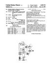
ABSTRACT
An instrument for precise measurement and setting of
distances has an electronically controlled scale compris
_z _______________________ "
1C 3 00, 601B 11 02
........ .L ..............
sag/s32- 33/125/A~
“116d digital display’ and *1 keybwd- The display and
33/1 ,1‘; 356/396’
keyboard are mechanically rotatable and connected by
I
ing optically active elements, an electronically con
[58] Field of Search ___________ __ 364/561, 562; 33/125 A,
electronic circuitry including a microprocessor. The
33/1 L, DIG 3; 250/202; 356/156, 170
light scale provides optical indicia, including a refer
_
[56]
ence point and a cursor, having positions which are
References cued
determined by keyboard entries and are displayed nu
U.S. PATENT DOCUMENTS
merically.
3,594,783
7/1971
Bullock .......................... .. 364/561 X
3,765,764
10/1973
Niss .................................... .. 356/156
’
28 Claims, 6 Drawing Figures
IIIIIHHI[HlllllllllllllllllllllllHIIIHIIIHIHHHllllllllllllllllllllllllllllllllllllllllllllllllllllllllllllllll
son/.5
2,0
DISPLAY
ml
II! [II ['21 E33 F1132
f M
I1"! IE1
IE1
[CU
[E]
E]
OF
U.S. Patent
Jun. 12, 1979
Sheet 1 of 5
4,158,229
HIHHIIHIIIHHHIIHIIIllllllllllllllllilllllllllllllllIllllIlllllllllllLHHHllllllllllllllllllllllllllllllllllllll
SCHLE
32
E33
E
k
7
-
_
"Z
1
' 561'
[1611/ KP
0201/6
cursor
to RP
me distance
def
amt set
6110/2
orcm
K
0
0=l
X:
US. Paient
Jun. 12, 1979
Sheet 4 of 5
4,158,229
70
a
B
1,2
C
4 _ T0 - /6 DECODER
0
Vac
74/54
6;, m
G2 9
/
0/23456789A5CDEF
/
7
/
0123255769/0/112/3M/5
/6
3/
a2
4
63
4-7046
. 5
DECUOEE
M5 M6
6
I l/
//2 [/3 //4
7
/
/
//8 //9 I20
1
4,158,229
2
an indication thereof on an associated calculator.
ELECTRONIC RULE FOR PRECISE DISTANCE
MEASUREMENT AND DISTANCE SETTING
Kimura requires a diffraction grating to effect light
measurement utilizing LED’s and photodetectors by
BACKGROUND OF THE INVENTION
grating. Such devices rely on complicated optical in
strumentation and do not provide for ordinary scale
1. Field of the Invention
The invention relates to distance measurement and
determination devices, and more particularly to elec
tronically controlled digital display of distances deter
mined with the aid of an optically active scale under the
control of keyboard instructions.
2. Description of the Prior Art
As is well known to those versed in the art of per
forming measurements of lengths and distances ranging
af?xing the detectors directly to the rear of an index
measurements of distances of either commonplace or
arbitrary scale factors.
Lewis U.S. Pat. No. 3,515,888 uses a reticle assembly
to determine position change with respect to a ?xed
reference by using optical gratings for chopping a light
beam. Niss U.S. Pat. No. 3,765,764 uses light de?ecting
means for coordinate measurements. A source projects
light onto a movable de?ecting means, thence to a fur
from the order of tenths of millimeters to several feet, a 15 ther measuring point. Grendelmeier U.S. Pat. No.
great variety of instruments with various degrees of
precision is available. In the order of increasing preci
sion, there are the meter stick or foot ruler, the vernier
caliper, the micrometer, and acoustical and electromag
3,599,004 determines scale placement utilizing equi
spaced photocells. A differential ampli?er is used to
permit measurement of displacements less than the cell
size. Such devices, while utilizing light sensing means
netic wave devices using the principle of wave re?ec 20 do not provide a portable means, under operator con
tion or used as interferometers. For ordinary measure
trol, for obtaining distance measurement comparable to
ments of lengths to a precision of tenths of centimeters,
ordinary meter-stick manual measurement, nor do the
the meter stick is used. Although this is the classical and
devices provide for variation of a scale factor under
time-honored method of measurement, it is not entirely
satisfactory. The user must overcome errors associated 25
with parallax and interpolation between scale divisions.
Furthermore, the scale markings are ?xed and conver
sion to other systems of units must be done as a separate
operator control. Moreover, the prior art devices do
not contemplate the use of an optically active scale for
distance setting and measurement.
SUMMARY OF THE INVENTION
operation, introducing additional errors. Previous de
vices competing with the meter stick have used me 30 The present invention overcomes the disadvantages
of the prior art and provides distance measurement and
chanical switching of electrical current in an electrical
resistor to perform measurements of length.
Gallacher et al U.S. Pat. No. 3,973,326 is illustrative
of such a prior art device, having a cursor on a movable
wand and a resistor extending along the length of the
wand. An electrical contact on the cursor contacts the
setting utilizing an optically active scale. In accordance
with the invention, a high resolution distance measure
ment device is provided for measurement in the British
system, the Metric system, or in any other user-defined
system of measurement. The apparatus disclosed herein
resistor, thereby forming a potentiometer with an out
put which is variable with cursor position. A digital
provides a digital numeric display of the measurement
mechanical switching mechanisms cause reliability
A series of optically active elements is spaced along a
line in close proximity to the straightedge of the device
to the user, as well as displaying a length when the
numeric distance and basic measurement unit are pro
voltmeter provides an indication of the distance mea
sured. Such devices are cumbersome to use and the 40 vided as inputs to the devices.
problems. Moreover, prior devices for performing ordi
to serve as a scale. A keyboard permits the user to input
coupled to electronic calculating devices so as to pro I numbers and to control the operations and functions
vide convenience and the greater power of electronic 45 performed by the subject device, with a digital numeric
nary measurements of length have not been directly
arithmetic.
display conveying the value of a distance setting, or the
The use of light sensing elements, particularly ?ber
optics, to determine distances in conjunction with
results of a length measurement, to the user.
counters and stored program computers is disclosed in
Accordingly, it is a principal object of the invention
to provide a distance measuring apparatus utilizing an
Rempert U.S. Pat. No. 3,598,978. However, relative
movement is required between the object and the light
optically active scale.
It is another object to provide a distance setting
sensing element, and the device does not operate as a
replacement for a ruler or meter stick having a scale
thereon. Scales are utilized in Zipin U.S. Pat. No.
arbitrary scale factors.
Yet another object is to provide computer activated
3,748,043, but only for viewing by photosensors to de
distance measurement devices of a portable nature.
termine a more accurate measurement by interpolation.
It is a further object to provide digital display for a
distance measurement device activated by computer
control.
It is still a further object to provide stored program
A display is provided for the determined distance which
is, however, not under operator control with respect to
means having an optically active scale for use with
either scale factor or other functions.
Other devices are known for distance measurement 60 control for a distance measurement device utilizing
optically active scales.
by optical means as illustrated by Renner et a1 U.S. Pat.
Another object is to provide multiplex control signals
No. 3,965,340 and Kimura U.S. Pat. No. 3,784,833.
Such devices require the use of gratings to effect light
for a computer controlled measurement device,
measurement. Renner et al, for example, detects a
whereby keyboard scanning, display and scale illumina
change in light transmission due to a relative displace 65 tion signals are multiplexed.
Yet another object is to present a highly reliable
ment between a ?xed interference grating (on a ?xed
caliper) and a movable grating (on a movable caliper).
The changed light transmission is detected to provide
length measuring device having high resolution,
thereby eliminating the need for interpolation.
3
4,158,229
4
PAO-PA6 and PBl-PB4 of unit 42 communicate with
BRIEF DESCRIPTION OF THE DRAWINGS
The foregoing objects, features and advantages of the
present invention will be made clear, along withother
advantages, features and objects thereof, by reading the
speci?cation along with the drawings wherein like
and drive'the keyboard and seven segment display of
the invention, and peripheral pins PAO-PA7 of unit 44
control the various elements of the optically active scale
numbers designate like objects throughout.
an output pin, the speci?c use being determined by the
FIG. 1 shows an apparatus embodying the present
invention.
FIG. 2 illustrates the internal components of the pres
content of av corresponding bit in an I/O direction regis
ently preferred embodiment and the electrical intercon
controls microprocessor 40, the system’s central pro
cessing unit.
nections therebetween.
_
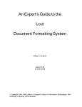
FIG. 3 shows the electrical connections for the key
board and display of the invention.
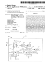
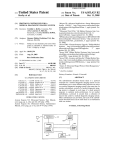
FIG. 4 shows the electrical connections to the scale
of the invention.
FIG. 5 shows a circuit diagram of supporting logic
used within the invention.
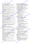
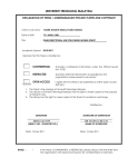
FIG. 6 is a flow chart illustrating the interaction
20
between the operator and the inventive apparatus.
10.
'
'
Each peripheral pin may be used either as an input or
ter contained within the unit, the register contents being
under the control of an operating program, which also
Central-Processing-Unit 40 is capable of performing
simple arithmetic logic operations, such as add, sub
tract, logical AND, OR, EXCLUSIVE OR, NOT, and
shifting. Control instructions such as jump, jump to
subroutine, return from subroutine, and conditional
jumps are also available. The microprocessor uses a
stack to store return addresses for subroutine calls. The
stack is located in the RAM of MCS 6530 chips 42 and
44.
DETAILED DESCRIPTION OF THE
The previously mentioned operating program is used
PREFERRED EMBODIMENT
to support functions of the Electronic Rule and is stored
in the ROM portion of the two MCS 6530’s. The pro
FIG. 1 illustrates a preferred embodiment of the elec
tronic rule. Three major elements of the device are 25 gram can be activated by an RST (reset) interrupt to the
MP8 6502. When the RST interrupt occurs, (when the
shown: an optically active LED scale 10, a digital nu
user of the electronic rule pushes the
key), the
meric display 20, and a keyboard 30. The keyboard
microprocessor fetches from a ?xed location in the
comprises a plurality of keys 32, including keys for
operating program an address, which points to the be
numerical entry and function keys.
The electronic rule disclosed herein can be used to 30 ginning of the operating program. The address is loaded
into the program counter and execution of the operating
perform length measurement or distance setting. In
program begins.
,
performing a measurement of distance or length, a lin
As previously mentioned, each of the two MCS 6530
ear distance between the left and right endpoints of an
object is determined. In distance setting, the user speci
?es a measurement unit and a numerical value, d. The
electronic rule will then select two points so that the
distance between them is d. These operations are de
?ned and further described in conjunction with FIG. 6,
chips contains 64 bytes of RAM, 1K bytes of ROM and
64 locations for input-output ports and timers. The
RAM portion is used to store variable data such as
user-de?ned measuring units, digits to be displayed,
locations of the reference point (RP) and cursor (X),
etc. The RAM is also used by the microprocessor as the
infra.
Turning now to FIG. 2, the various components 40 system stack.
Each I/O port in a MCS 6530 chip is associated with
utilized in the preferred embodiment, and the intercon
» nection thereof, are shown as including a microproces
an I/O data register and an I/O direction register. Both
registers can be accessed by providing a unique address,
which is part of the entire memory address space. That
6502 and two peripheral interface/memory units of 45 is, the I/O ports are treated like memory storage loca
tions.
large scale integraton (LSI chips available from MOS
Referring now to FIG. 3, the keyboard 30 and display
Technology as chips MCS 6530) shown at 42 and 44.
20 are shown in greater detail. Speci?cally, seven~seg
Each LSI unit includes two input/output registers, two
ment display units 51-56 are shown, each being driven
peripheral data buffers, an interval timer, two data con
by lines 57. A speci?c display element is chosen for
trol registers, an address decoder, a data bus buffer, a
activation by one of transistors Ql-Q6, activated and
chip select unit and two memory units, a mask program
deactivated by signals output by decoder 60. Decoder
mable l024>< 8 ROM and a 64X 8 static RAM.
sor chip 40, such as is available from MOS Technology,
Inc. of Norristown, Pa. under the nomenclature MP8
These units as well as the microprocessor unit are
60 comprises a BCD to decimal decoder such as com
monly available under the designation SN 74145 from
described in Appendices G and H in MOS Technology
55 Texas Instruments. The input lines 62 to decoder 60 are
“KIM-1 User Manual”.
connected to the peripheral bus for connection to pins
Support logic unit 46, shown more fully in FIG. 5, is
PBl-PB4 of unit 42.
connected to the microprocessor and LSI units. Unit 42
interfaces with both keyboard 30 and a seven segment
display 20, shown combined in block 45. Unit 44 is used
to interface with scale 10.
A bus structure is utilized for communicating be
Additional output lines 64 from decoder 60 are con
nected to the three rows of the keyboard in the pres
ently preferred embodiment. Pins PAO-PA6 of unit 42
are connected to the columns of the keyboard and also,
tween the various units as follows- An address bus 47,
through open collector inverters 66, to display units
having lines ABO-AB11 therein, communicates between
microprocessor 40 and units 42 and 44. Additionally,
51-56.
Under control of the operating program, display 20 is
lines AB10 and AB11 therein communicate with sup 65 activated by scanning the several display elements. The
port logic 46. A data bus 48, containing lines DBO-DB7
therein, further provides communication between the
microprocessor and the two LSI units. Peripheral pins
scan is achieved by the proper coding of pins PB1—PB4,
resulting in sequential selection of transistors Ql-Q6 by
the action of decoder 60. For each selected transistor,
5
4,158,229
and correspondingly selected display element, the num
ber to be displayed is obtained from a table in unit 42
and converted to a code suitable for seven segment
display which is placed in a register. Pins PAO-PA6,
caused by the program to act as output pins, convey the
proper seven-segment code to the display element. The
operating program also selects the proper scale ele
ments to display RP and X. After performing its display
function, the operating program causes keyboard 30 to
10
be scanned.
6
preferred embodiment contemplates the use of 121 ele
ments in scale 10, it is clear that with no modi?cation of
hardware design the eight output lines from LSI unit 44
in conjunction with decoders 68 and 70 may equally
address 256 components of a scale. Similarly, with
slight modi?cation, such as increasing the storage avail
able to unit 44, and with the use of different decoders 68
and 70, virtually any number of elements may be incor
porated within the scale. In the presently preferred
embodiment, two elements are activated to display two
Keyboard scanning is achieved by providing sequen
points. Conceivably, scale displays of more than two
tially the codes for activating output lines 00-02 of
decoder 60. The codes are applied sequentially by pins
elements, or of variable numbers of elements or of a
PB1-PB4 of unit 42. For each code, one of lines 00-02
is chosen, and one of rows 0—2 of keyboard 30 is acti
vated. During each such activation, pins PAO-PA6,
?xed number of variable elements may be desired. For
any of these possibilities the elements to be activated
may be selected either by scanning and multiplexing
elements along a row, or by simultaneous activation of
all selected elements. The preferred embodiment pro
vides multiplexed activation of the LED’s selected to
lected, thus scanning each key in the selected row of the
represent RP and X.
keyboard. If a key depression is detected, the operating
program executes the function represented thereby. If 20 Turning now to FIG. 5, the supporting logic shown
now caused to act as input pins, are sequentially se
not, the next row is scanned. After execution of the
function (or determining that no key was depressed),
the program again energizes the display and scale.
The functioning of the main operating program is
in FIG. 2 is illustrated as comprising a timer 72 con
nected to CPU 40 as well as to LSI units 42 and 44.
Additionally, a crystal circuit is utilized in the timing
connections, thereby providing a separate phase for the
.
more clearly shown in Appendix A, which includes a 25 logic circuitry.
In operation, the use of an optically active scale per
?ow chart representation thereof. The various subrou
mits, inter alia, provision of a standout optical contrast
tines are shown in Appendix B. As is apparent from the
preceeding description, the inventive device thus in
cludes a means for multiplexing the display and key
board sensing, thereby providing for the use of fewer
pins, lines, connections, and other hardware. In view of
for the endpoint optical elements in comparison with
the interval being measured. That is, while the two
LED’s at the endpoints of a line interval being mea
sured are activated, remaining diodes are not and the
the high operating speeds available in digital computers,
endpoints only are made conspicuous, thereby decreas
such multiplexing does not adversely affect the user’s
ing the chance for measurement error. The system may
perception of the display and scale. Speci?cally, objec
similarly operate by activating the optical elements
visible light may be used. Thus, while it is known to use
called the cursor (or X). When the power is turned on,
RP is automatically set to the left margin of the LED
scale and the cursor position will be the same as RP.
tionable ?icker and other disadvantages do not result 35 along the entire interval, or by activating all elements
except those along the interval being measured, rather
from the approach used herein.
than only the endpoint elements. Either of these alterna
Referring now to FIG. 4, scale 10 is shown compris
tives also provides enhanced contrast and reduction in
ing a plurality of active optical elements disposed at
measurement error. In performing a measurement, three
intersections of addressing lines for the elements ema
phases of operator-machine interaction are contem
40
nating from decoders 68 and 70. The decoders are avail
plated. The following discussion may best be under
able, for example, under the label SN 74154 from Texas
stood with reference to FIG. 6 where circles corre
Instruments, and comprise four-to-sixteen decoders. A
spond to operations by the user and rectangles to values
particular optical element is activated by selecting the
of registers internal to the apparatus.
speci?c row and column output lines at whose intersec
tion the element sits. The presently preferred embodi 45 In a ?rst phase, a reference point is selected. As dis
cussed above, only two scale positions are activated.
ment contemplates the use of light emitting diodes as
The two positions may coincide. One position is called
the scale elements, but it is recognized that any elements
the reference point (hereinafter RP), and the other is
which affect the absorbance, re?ectivity, or emission of
optically passive scales for conventional measurement,
including scales which are inscribed for absorbing or
reflecting light with greater intensity than the medium
When the buttons E and E] are depressed, the
in which the scale is embedded, the present invention
utilized optically active scales. It is contemplated that
any scale comprising electronic components which can
emit visible light or absorb visible light from another
pressed. The cursor position will propagate to the right
light source under the control of the user may be used.
More particularly, the optically active scales contem
plated herein include any scale having components
cursor position will be changed. The new cursor posi
tion depends on the previous cursor position, the button
depressed, and the length of time a button remains de
(or left) as long as E], (or E) is depressed. When
the user positions the cursor adjacent to one endpoint A
of the object to be measured, [IE may be depressed to
wherein one or more of the following properties of light 60 indicate that this position has been selected as the new
RP. The light for the old RP will be turned off and,
are controlled whether by electrical, electromagnetic,
until the next time RP is changed, any later measure
thermal or magnetic ?elds: emission, absorption, re?ec
ment will be relative to this point. That is, a distance to
tion and transmission, for example. Such elements in
the left of RP will be displayed as a negative number on
clude light emitting diodes, as presently selected for use
65 the digital numerical display and a distance to the right
in the scale, liquid crystal elements, etc.
as positive. The convention can be reversed by depress
The speci?c elements of the scale are selected by LSI
unit 44 providing output signals on peripheral lines
PAO-PA7 to decoders 68 and 70. While the presently
ing E] (flip sign) key. When 11:‘ is depressed twice,
the defaultconvention will be used. It is noted that the
4,158,229
7
user can also choose to physically translate the whole
rule so that any lighted LED can serve as the RP.
Having determined a new RP, the cursor is moved to
a second endpoint of the object to be measured and the
distance between RP and cursor displayed. It is possi
ble, however, that different measurement units might be
desired by the user. Accordingly, a second phase is
provided wherein the speci?c unit to be used is deter
mined. When entering the second phase, the cursor
position coincides with RP. If the user selects a conven
tional distance unit such as inches (or centimeters), he
can depress [E , (or
), which will move the
cursor position to the right by one inch (or one centime
ter). The display will have a value 1. If the units are
arbitrary then the calibration point CP must be de?ned.
The user then depresses
or
to move the cur~
sor position, similar to the steps in the ?rst phase, until
it is adjacent to the calibration distance. He further
depresses
and enters the numerical value C of the
calibration distance by depressing the digits in se
quence. It is noted that C may be negative. The value of
C will be displayed. The user then depresses E] to
indicate that the calibration distance is to be taken as C
units. At this time, the calibration phase is complete and
8
this case, RP and the measurement unit will not be
changed.
As an illustrative example, where it is desired to de
termine the length in centimeters of an object, the scale
is placed against the object. If the object extends, for
example, from the 10th LED through the 63rd, the
operator would follow the procedure outlined above
and, after turning on the device, move the cursor to the
right until it is adjacent to one of the object endpoints,
for example the left endpoint at LED 10. Depressing
the RP button will select that position as the reference
point. Since the distance is desired in centimeters, the
user may depress the
button which moves the
cursor one centimeter to the right and displays a 1 in the
digital display. Further depressing the
button to
move the cursor to the right, to the 63rd LED, in this
example, the user then observes the distance in centime
ters on the numerical display.
Were the user to desire a measurement in some arbi
trary scale, as would be the case in reading a map, for
example, and assuming the distance is still between the
10th and 63rd LED, the following procedure will be
followed: After selecting the reference point, the cursor
is moved to the right from the reference point a particu
the display shows the distance C between the RP and 25 lar distance. In the case of map reading, the cursor is
moved to the right by a distance corresponding to the
the cursor position.
The third phase is the measurement phase. When the
user positions the cursor adjacent to the other endpoint
B of the object, the distance between A and B will be
converted to proper units and displayed. The orienta
tion of the vector from A. to B will also be displayed
with a negative number to mean left-going and a posi
tive number to means right-going unless a reverse orien
tation has been selected by depressing
.
The distance setting process can also be described as
a 3-phase procedure with the ?rst two phases identical
to those of the length measuring process. During the
third phase, the user enters a number, j, which may be
negative, by pressing the digits ofj in sequence folled by
E1. The number j will be displayed and the electronic
rule will move the cursor (in the direction depending on
particular map-scale factor. Thus, where 5 inch equals
one mile and a map scale is provided, the cursor ma be
moved to the right by l inch. At this point, the
button is depressed and the numerical value being mea
sured is entered. In this example, the number 1 would be
entered‘if the desired distance is in miles. Depressing of
the E1 button indicates the calibration distance as
being 1 unit. Finally, with the scale against the distance
being measured, the cursor is displaced to the 63rd
LED and the position between the reference point and
cursor is displayed numerically in miles. As a further
example of the effectiveness of the present invention, in
a map-scale having % inch equivalent to ten miles, the
calibration step described above would be modi?ed by
entry of the number 10 rather than 1 from the keyboard
after depressing the
button. The display would
then provide the distance in miles.
the sign of j) to a position such that the distance be
tween RP and the cursor position, in the units speci?ed
Clearly, the scale need not provide a linear measure
by the user, is j.
45 ment. Thus, it is contemplated that scales having opti
‘In both the length measuring and the distance setting
cally active components which are themselves non-lin
processes RP is defaulted to the leftmost end of the rule
early distributed along the scales may be used. The
if the user chooses not to set his own RP position. The
measurement unit is defaulted to the distance between
two neighboring LED lights if the user does not specify
his own. In FIG. 6, the control sequences described
above are summarized as a ?ow chart. At each circle
the speci?c user operation represented by the circle will
cause the actions described in the associated rectangle.
elements may be logarithmically spaced, for example.
Similarly, the elements may be linearly spaced but the
measurement phases, under the control of the operating
program, may provide displays corresponding to non
linear distances. Thus, for example, the exact distance
along a logarithmic chart might be measured using the
present electronic rule under a logarithmic subroutine
Each circled operation represents pressing of the simi 55 in the operating program. Additionally, it is recognized
larly labeled button by the user on the keyboard. The
registers represented by the rectangles include:
RP-position of the reference point
X—position of cursor
D',—number displayed
U—-the unit conversion factor in terms of number of
LED’s
IN,CM—constant unit conversion factor for inch or
centimeter.
that the scale need not be linear but may be curved, and
may, for example, be provided along a French curve.
As an example of the distance setting procedure, a
user may follow Phases 1 and 2 as previously outlined,
60 and may provide a distance either in centimeters,
inches, or some arbitrary unit. Thus, once a reference
point is determined, the inch or centimeter button may
be depressed or an arbitrary unit may be entered by
moving the cursor to a calibration distance and entering
Any sequence of operations not included in the How 65 the numerical value of that distance. The third phase of
chart will be considered illegal. The display will blink
all the seven segment lights when an illegal operation is
detected. The user can press
to clear the display. In
distance setting, however, requires entry of a number
and depressing the [B button. Thus in the map exam
ple previously used, once the scale had been entered as
4,158,229
a
10
9
5 inch per ten miles, for example, by displacing the
cursor { inch from the reference point and by depress
(9) BCD-This routine converts a binary number to
its binary-coded-decimal (BCD) equivalent, which will
ing the CP button followed by entry of the number
10 from the keyboard and by depressing of the 13
then be used to drive the seven segment display.
(10) ERROR-This routine blinks all the lights in the
button, the user may choose to display a distance repre 5 seven segment LED’s to signal an error. The routine is
sentative of 42.5 miles. To do this, the number 42.5
activated only when illegal operations are detected or
would be entered by the keyboard, the E] depressed,
when an operation exceeds the precision or margins of
and the cursor would be moved by the operating pro
the electronic rule.
gram to 42.5 miles (at a scale of 5 per ten miles) from the
When the power is initially turned on and the [E
reference point. The user would then have the reference
is depressed by the user, an RST interrupt takes place,
point and cursor separated by the distance equivalent to
which starts the SCAN sequence. The SCAN routine
42.5 miles at that scale factor.
will drive the display and the scale and monitor the
The software used to support the functions of the
keyboard repeatedly. When a depressed key is detected,
electronic rule is the operating program. The program
its function is then executed by EXEC. If an error is
is stored in the two 1 K byte ROM of the MCS 6530
detected, ERROR routine will ?ash the display, which
chipes. Basically the program follows the flow of con
can only be cleared by pushing the [El key. Each
trol as shown in FIG. 6.
The primary concept used in monitoring the key
board and in driving the LED’s in scale display is to
alternate between reading the keyboard and writing to
time the [El key is depressed, the electronic rule is
initialized and the operating program re-started.
20
the display and scale at such a speed that the multiplex
ing is not discernible.
The operating program consists of a main program
and several subroutines. The main program and the 25
major subroutines are described brie?y here:
(1) MAIN-This program can be entered as a result
of an RST interrupt. Upon entering the program, data
variables will be initialized by calling subroutine INIT.
SCAN will then be called to execute the scan cycle, i.e. 30
to display the scale LED, to activate the numerical
display, and to read the keyboard in a multiplexed man
ner. When a key in the keyboard is depressed by the
user, the program will also branch to a segment of code
labeled EXEC, in which the function associated with 35
the key is executed. If no key is depressed, the program
will repeat the scan cycle.
(2) INIT, INITl-This is the initialization routine‘
which sets up the initial values of all variables used in
the operating program and moves RP to the left margin
of the scale. INITl is a different entry point to the
subroutine.
(3) SCAN-The routine ?rst selects each of the six
seven-segment units in sequence to display a number
(with possibly a sign and a unit), then turns on the two 45
LED lights in the scale that correspond to RP and X
(cursor), and checks to see if any key in the keyboard is
depressed. If no key is depressed, the same control se
quence is repeated, that is, displaying a number, turning
on RP and X, and checking the keyboard. If a key is 50
found depressed, the control will set up a nonzero value
in the accumulator A. Otherwise, A will be cleared to
(4) CONV-This routine uses an internal table to
APPENDIX A
OPERATING PROGRAM DESCRIPTION
Background
1. When the power is turned on and the IE key is
depressed, an RST (Reset) interrupt is generated
which will start the operating program.
2. Each 6530 chip includes a 1024 byte Read-only
Memory (ROM). The operating program is to be
stored permanently in the 2048 bytes of ROM in
the two 6530 chips (6530-X and 6530-Y).
3. Each 6530 chip includes a 64-byte Random Access
Memory (RAM). The total 128 bytes of RAM is to
be used for (a) the storage area of the stack to be
used by the microprocessor 6502 to save return
addresses in subroutine calls and (b) the data areas
storing data variables related to the user opera
tions. The data variables related to the item (b) are
listed under “Data Constants and Variables.”
In the flow-chart description of the operating pro
gram, “JSR XXX” is used to mean “Jump to sub
routine whose name is XXX”. This has the affect of
saving the return address (RA) in the stack (which
is mentioned in 3(a) above). The symbol “RTS” is
used to mean “return from subroutine”, which is
the last instruction in execution in a subroutine and
has the effect of directing the control to the address
(RA) saved on the top of the stack as well as pop
ping RA off the stack.
. zero. The routine calling SCAN can check the contents
of A to determine if a key is depressed.
The various subroutines outlined above are shown in
?ow chart format in Appendix A and B.
55
convert a number into bit patterns which correctly
select the segments of one seven segment display unit,
causing the number to be displayed in the selected unit.
(5) LED--This routine outputs a value to the MCS
6530 unit 44 peripheral pins, causing one of the LED’s
in the scale to turn on.
(6) KEY, ONEROW-These routines read the key
board to determine which key is depressed. ONEROW
checks only one row of the keys. KEY calls ONEROW 65
5. The entire operating program is described as a
collection of routines with each routine repre
sented as a ?ow-chart.
6. An italic name followed by a colon (z) is used as a
label for the nearest statement.
DISPLAY, KEYBOARD, and SCALE refer to
the three corresponding components of the Elec
tronic Rule.
8. All numbers are in decimal unless speci?ed other
wise. Hexadecimal numbers are indicated with a
subscript H.
repeatedly to check every row.
(7) DIVD-A division routine.
(8) MULT—A multiplication routine.
9:)
‘
Beginning of a routine, name of
the routine is enclosed.
4,158,229
11
12
-continued
-continued
An action, a program statement
TOTAL
BOUND
Total number of lights in SCALE.
Maximum number of digits user can enter
(integer or fractional portion).
5
TABLE
(entry 0) -
_
A decision box
10
_
7-segment code for l
(entry
(entry
(entry
(entry
(entry
(entry
(entry
7-segment
7-segment
7-segment
7-segment
7-segment
7-segment
7-segment
2)
3)
4)
5)
6)
7)
8)
-
(entry 9) -
Brgnch'flg gg?omls’l’ ‘he
su routine
A “go to” statement, the destination
for
for
for
for
for
for
for
2
3
4
5
6
7
8
7-segment code forNo display (null)
(entry H)
7_Segmem code for i
(entry 12)
7-segment code for 0
(entry 13)
7-seg1nent code for —
7.
is indicated inside the circle.
_
code
code
code
code
code
code
code
7-segment code for 9
(entry 10)
s an returns.
15
C)
7-segment code for 0
(entry 1) -
ABOUT SIGN CONVENTION:
20
1. By default, if XZRP then the distance is displayed
10. A is the accumulator of the 6502 microprocessor.
18 is the BCD-decimal decoder 60 shown in FIG. 3.
as positive. If X<RP, then it is negative. X is the
cursor position,
2. The user can reverse this convention by hitting the
F key. This will cause no change in the positions of
DATA CONSTANTS AND VARIABLES
(Note: The size (number of bytes) of the variables or 25
RP and X per see, But this will cause the reversal of
the signs. Hitting the F key again will return to the
constants is not speci?ed.)
default convention. X is the cursor position.
_
_
3. The — (minus) key by itself does not reverse the
vmbles (located “1 RAM)‘
Reference point position
RP
X$$§$isas X m
discussion)
D
sign convention. It merely causes the minus sign to
be displayed_
30
cursor position
4. During the distance setting operation, one can
depress the minus key, followed by a series of nu
Numerical value of the distance to
be dlsplf‘yed’ "Pmemed “‘ 39D
form with each segment of 4 bits
for a decimal dish. The leftmost
meric keys to cause the distance to be displayed.
The following possibilities may occur in a distance
35
tt.
t.
se mg opera lon.
X . th
is
.t.
e cursor posl ion.
byte of D, called sign byte of D
stores the sign (— or no display for +)
of the distance. All segments are
INCM
index pointers to TABLE.
An index pointer to TABLE, 11 for i
UNlTSIGN
(inch)
1? f“ c (cm) °‘ _‘° ‘W “"1"
_
Sign of UNIT, either 1 for negative
or
UNIT
for POS'FW‘F'
CPMOD
40 Sign convention
default (UNITSIGN=0)
default (UNITSIGN=0)
reverse (UNITSIGN=I)
_
Umt factor, indicating the number
of lights for each basic measurement
E
‘
Minus
reverse (UNITSIGN=1)
key
depressed
YES
NO
YES
Relative positions of RP,X
x to the left of RP
x to the right of RP
x to the right of RP
NO
X to the left of RP
45
“Amt; self’cfd by thehusg' h
5. When the user is de?ning his own measurement
is dgl‘g'ganwlse?egm
unit using CP key, the sign of the unit depends on
either 1 for Cp mode 0,- o for distanc'e
the relative positions of RP and X, and whether the
setting.
minus key is depressed or not. The following cases
DIGIT
The “mt men‘ dig“ ?lmed by ‘he
MINUSFLAG
A flag indicating whether the user
DIGIT#
for depressed or 0 otherwise.
583m" of dlgns entered by the
50 I
are possible. X is the cursor position.
user.
has depressed the - key, either 1
.FLAG
A ?ag indicating whether the user
has depressed the .key (decimal
point), either 1 for depressed or
0 otherwise.
SUM
M.
Relative positions of X,RP
55 x to the right of RP
X to the right of RP
X to the left of RP
vX to the left of RP
1:23:15
depressed New sign convention
YES
NO
YES
reverse (UNITSIGN= 1)
default
default
reverse (UNITSIGN=1)
NO
Integer portion of the number entered
by the user.
FSUM
Fractional
'
DA’ DB’ Q
entered by ‘she “set.
D‘v'del'd' ‘1mm’ and qum‘em'
ortion of the number
MA, MB, P
Multiplicand, multiplier, and product,
respectively.
respectively.
INFACTOR
CMFACTOR
Constants (located in ROM):
Number of lights for one inch
Number of lights for one cm.
60
'
I
EXPLANATION OF MAIN:
There are three J SR SCAN statements in the main
_
_
prog'ram MAIN- If the Powerls Just turned on and no
key 15 depressed, the control stays in the loop of the
65 second I SR SCAN (starting with Repeat). When a key
is depressed, the control enters into the third J SR
SCAN which double checks if the key is indeed de
pressed (not nolse). If so, go to EXEC. Otherwise, the
4,158;229
»
1s
14
control returns to the second I SR SCAN. After EXEC, - v Y, J SR SCAN (starting with Start) and waits until key is
which performs the function associated with the key“
released‘.
'
depressed, the control returns to the loop of the ?rst
PROGRAM NAME: MAIN
FUNCTION: This is the main body of the operating program
um‘.
.
RS ke is deressed
MA IN
I SR NIT
Start:
J SR SCAN
No
Rem“
‘
11am-
%
%
Yes
No
Inm-
%
Y“ Q
No
FUNCTION: To perform the speci?c operations as defined for the function
keys of the KEYBOARD.
Exec:
M
‘w
i No
Yes
‘
I
' '
" ‘ ‘
4,158,229
15
16
-c0ntinued
M
M
M
M
M
M
M
M
M
M
M
M
M
A = ODH?
No
Yes
17
4,158,229
-continued
No
CP Key:
RP Key:
Set sign byte of
D to 10 for
18
4,158,229
19
-continued
—Key:
MINUSFLAG = 0?
Start
(ignore -Key)
DIGIT# = 0?
No
(ignore -Key)
Yes
INUSFLAG <- 1 I
Set sign byte of
D to be 13 (to
display —)
F key:
I UNITS]
J SR FLIPSIGN
FLIPSIGN V
FLIPSIGN
C Key:
Set sign byte of
D to 10 for
7
20
4,158,229
23
-continued
‘
->Key:
'
(X register is a hardware
x re st“ ‘- XCUR
register in the microprocessor 40.
_
.
_
X re
X register >
TOTAL?
JSR ERROR
JSR El
Sign byte of D <
13 (for minus
X < RP:
‘
x > RP:
'
‘u
Sign byte of D <_
10 for
Divide:
It is used as a temporary
,
ter <- 1'. re ster
sitive
storage.)
1
. 4,158,229
25
-continued
SUM <- Integer portion of Q
FSUM 4- gactional portion of
PSIGN
from
FLIPSIGN
0-9 Key:
(integer
portion)
(fractional portion)
FSUM
10
25
4,158,229
27
‘ 28
-continued
SUM ‘- P % DIGIT I
IFSUM <- P I; DIGIT I
FSUM (- 0
J SR BCD
BCD
: Key’
CPMODE = 0
(distance setting)
CPMODEI
(positive)
(default
UNITSIGN =
sign
(negative)
0
(re
conven-
vcrs'ed
no“)
conventiséil)1
(de_
(i'eversed
fault
sign convention)
3115;15:131
Right:
Left:
A > Total?
JSR ERROR
A <- RP — P
A ( 0