1
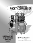
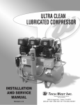
ULTRA CLEAN
SURGICAL VACUUM
INSTALLATION
AND SERVICE
MANUAL
Revised 8-08
TECH WEST INC.
Manufacturers of Dental Vacuum
and Air Systems
2625 N. Argyle Ave. • Fresno, CA 93727
(559) 291-1650 • (800) 428-7139 • FAX (559) 348-9677
ULTRA CLEAN
SURGICAL VACUUM
INSTALLATION AND SERVICE MANUAL
This manual is for the installation and service of Tech West’s Ultra Clean Surgical Vacuum.
CONTENTS
Installation
Location Requirements
2
Figure 1: Wire and Breaker Sizes
2
Ultra Clean Surgical Installation Steps
3
Ultra Clean Surgical Connections
4
Ultra Clean Surgical Safty Precautions
5
Ultra Clean Surgical Start Up
5
Ultra Clean Surgical Maintenance
6
Ultra Clean Surgical Motor Assembly Breakdown
7
Dual Ultra Clean Surgical Vacuum Assembly
8
Triple Ultra Clean Surgical Vacuum Assembly
9
Ultra Clean Surgical Check Valve Assembly
10
Vacuum Line Sizing Chart
11
Wiring Digram
11
TROUBLE SHOOTING
Trouble Shooting Chart
12
Maintenance & Service Records
13
1
ULTRA CLEAN SURGICAL VACUUM
INSTALLATION
1. SURGICAL VACUUM LOCATION REQUIREMENTS
The Ultra Clean Surgical Vacuum location should be level, accessible and well ventilated.
If the Ultra Clean Surgical Vacuum will be located in a confined space, provide adequate ventilation.
Electrical
(1)
Line voltage must be within the limits of Figure 1 below. (Install a “buck-boost
transformer” if line voltage is not between these values.) Provide a separate line for
each motor. Circuit breaker switches must be 20 - 30 amp depending on model
and voltage necessary.
(2)
Local code may require you to provide one quick disconnect (safety switch) for each
compressor motor.
(3)
See Figure 1 below for breaker size and line voltage.
CAUTION - Voltage must be 208/230 V or motor damage may occur.
(4)
The electric motors have been designed to operate within a +/- 10% range from the rated
nameplate voltage. Insure that the electric power source is the same as shown on motor
name plate. Single phase motors are equipped with automatic reset type thermal protectors.
Figure 1: Recommended Wire and Breaker Size
Model
Voltage
Amperage
Wire Size
(Gauge)
Recommended
Breaker Size
14.4
12
20
21.6
10
30
Dual Head Compressors
DSV-075-20
208/230
Triple Head Compressors
DSV-075-30
208/230
2
ULTRA CLEAN SURGICAL VACUUM
INSTALLATION
2
2. INSTALLATION STEPS
This dental vacuum should only be installed by qualified personnel. Should any questions arise during the installation, call Tech West Technical Support between the hours of 7:00 a.m. to 4:00 p.m.
(Pacific Standard Time).
Place the vacuum in a clean, dry, well ventilated area, on a solid, level surface. Consider sound
level and insulate as needed. Be sure that adequate ventilation is available as the vacuum is air
cooled. Ambient temperature in the equipment room should be within the temperature range of 40
degrees Fahrenheit minimum to 100 degrees Fahrenheit maximum.
(a) Check the shipping carton for damage. This could detect damage to the unit which might
otherwise be overlooked. Remove cardboard shipping carton.
(b) Remove the Surgical Vacuum from its shipping skid. Inspect the unit for damage.
Oilless vacuums are shipped bolted to a pallet. This pallet is intended for shipping only
and should be discarded.
(c) Remove installation kit attached to pallet. It should contain the following:
(4) Isolation Feet
(1) 5’ Flexible Air Hose
(d) Install isolation feet on tank legs.
(e) Move vacuum into place and level by observing bubble level on compressor platform.
(f) Wiring instructions:
(1) Have all electrical connections made by qualified personnel only. All connections
should be in accordance with local codes.
(2) Use the chart on page 1 to help determine the proper line and breaker size for
the unit that is being installed.
(g) Install the vacuum line from the vacuum tank to the building supply.
(h) Install the 1” flex alternate air hose from the vacuum motors to a fresh air supply if required by
local code.
3
ULTRA CLEAN SURGICAL VACUUM
INSTALLATION
2
3. CONNECTIONS
Figure 2
30
40 50
60
20
7
10
0
8
psi
90
100
Electrical Connection
to disconnect and
electrical panel
220 v
Alternate Air
Connection
to fresh air supply
4
ULTRA CLEAN SURGICAL VACUUM
INSTALLATION
2
4. SAFETY PRECAUTIONS
• Keep fingers, foreign objects and clothing free from rotating parts and do not touch hot surfaces.
• Never attempt to service an operating unit.
• Isolate unit from building system before servicing.
• Disconnect all power before servicing. The thermal protector in single phase motors
automatically starts motor when device resets.
USE OF THIS PRODUCT IN OR NEAR EXPLOSIVE ATMOSPHERES, OR FOR
PUMPING MIXTURES OTHER THAN ATMOSPHERIC AIR MAY CAUSE AN
EXPLOSION OR FIRE, RESULTING IN PERSONAL INJURY OR DEATH.
2
5. START-UP STEPS
(a) Make sure the shut-off valve from the vacuum tank is closed.
(b) Turn the breaker from the panel to the “ON” position.
(c) Turn power “ON” from the toggle switch on the vacuum. The vacuum unit should run quietly
and vibration free. The storage tank should start to build vacuum.
(d) The vacuum will run until the pressure gauge reads 22” hg. The vacuum then will automatically
shut off.
(e) Using soapy water, check the vacuum plumbing hook ups for leaks. Repair leaks if needed.
(f) Pressure test the entire plumbing system for leaks. Use the storage tank pressure gauge to
monitor a pressure drop. After the plumbing system has been pressurized for 30 minutes,
re-check the gauge for pressure drop. If there is a drop in pressure, find and repair all leaks
in the office plumbing.
(g) If motor fails to start or slows down significantly under a load, shut off and add a disconnect from
power supply. Check that the voltage is correct for the motor and that the motor is turning in the
proper direction. Vane life will be drastically reduced if the motor is not operating properly. Vanes can
break or be damaged if the motor/pump runs in the wrong direction.
(h) Caution: Do Not Lubricate. This product uses grease-packed bearings and does not require
additional lubrication. Adding greae or petroleum products to this unit will reduce performance and
can potentially damage the product. Do not allow moisture, liquid or contaminants to enter the pump.
(I) Complete and mail in the warranty card for the Surgical Vacuum within ten days of installation.
AIR LEAKS ARE THE MAIN CAUSE OF SYSTEM FAILURES.
5
ULTRA CLEAN SURGICAL VACUUM
INSTALLATION
2
6. GENERAL MAINTENANCE
Check intake and exhaust filter after 500 hours of operation. Clean filters and determine how
frequently filters should be checked during future operation. This proceedure will help to assure
product performance and maximize service life.
(a) Remove the end cap and filters. Inspect the filters for rips, tears, cuts, brittleness and excessive
foreign materials.
(b) If the filters are in good condition, clean with compressor air. Reinspect for wear and general
overall condition.
(c) Check the condition of the O-ring on the internal filter. It should be soft and flexible. Replace if
it shows signs of age.
(d) Re-install the original filters of new filters if necessary. Replace the end cap finger tight.
7. PERIODIC SERVICING
Vane Replacement:
(a) Disconnect electrical power to motor.
(b) Remove filters.
(c) Remove the five (5) screws and sound cover chamber. Use a small hammer to tap on the sound
chamber . Do not use a screwdriver to pry.
(d) Remove the six (6) end plate bolts.
(e) Remove the end plate. Check direction of the beveled edges on the vanes then remove.
(f) Clean the body and rotor slots with compressor air.
(g) Check the end plate, rotor, and body for scoring and wear.
(h) Insert the new vanes, insuring that the beveled edges are facing the correct direction.
(i) Replace the end plate.
(j) Check the sound chamber gasket for damage.
(k) Re-install the sound chamber and filters.
6
ULTRA CLEAN SURGICAL VACUUM
PARTS LIST
2
NOTE: Tech West does not
recommend using Teflon Tape
when installing intake filters.
7
5
3
9
1
6
10
12
4
11
8
14
15
Vibration eliminators must be
used for direct mount applications.
Do not hard mount unit to existing
configuration without isolators.
13
16
KEY
OIL-FREE VACUUM MOTOR 1HP
PART NO.
DESCRIPTION
UNIT
1
MOTOR ASSEMBLY
1
2
SHAFT KEY
1
3
VANE ASSEMBLY SPACER
1
4
VANE ASSEMBLY WASHER
1
5
VANE ASSEMBLY SCREW 1/4 - 28 X 3/4” LG
6
VANE ROTOR
1
7
VANE KIT
4
8
CYLINDER
1
9
CYLINDER SHROUD
1
10
END PLATE
1
11
SOUND CHAMBER TO END PLATE GASKET
1
SILENCER
1
13
SOUND CHAMBER
1
14
SOUND CHAMBER TO END PLATE SCREW 1/4 - 20 X 2 1/4” LG
15
CYLINDER TO MOTOR SCREW 1/4 - 20 X 2: LG
12
16
AS-375
GAF-100
FILTER KIT (10 FELT ELEMENTS, (2) O-RINGS, (2) FILTER INSERTS)
7
2
1
2
3
4
5
30
40 50
60
20
7
10
0
8
psi
90
100
7
6
8
DUAL ULTRA CLEAN SURGICAL VACUUM
KEY
PART NO.
DESCRIPTION
UNIT
1
SBHA-14-375
STEEL BRAID HOSE ASSEMBLY 3/8 X 14
1
2
SBHA-18-375
STEEL BRAID HOSE ASSEMBLY 3/8 X 18
1
3
RIC-GAST
RUBBER MOTOR MOUNT
8
4
CV-500
1/2” CHECK VALVE
2
5
BV-250
1/4 BALL VALVE
1
6
PMG-VAC
7
PSC-DV
8
REV-100
VACUUM GAUGE
1
VACUUM PRESSURE SWITCH
1
RUBBER MOUNTING FOOT
4
8
1
3
2
4
7
5
30
40 50
60
20
7
10
0
8
psi
90
100
6
8
TRIPLE ULTRA CLEAN SURGICAL VACUUM
KEY
PART NO.
DESCRIPTION
1
SBHA-14-375
STEEL BRAID HOSE ASSEMBLY 3/8 X 14
1
2
SBHA-18-375
STEEL BRAID HOSE ASSEMBLY 3/8 X 18
1
3
SBHA-23-375
STEEL BRAID HOSE ASSEMBLY 3/8 X 23
1
4
RIC-GAST
5
CV-500
6
PMG-VAC
7
PSC-DV
8
REV-100
RUBBER MOTOR MOUNT
UNIT
12
1/2” CHECK VALVE
3
VACUUM GAUGE
1
VACUUM PRESSURE SWITCH
1
RUBBER MOUNTING FOOT
4
9
5
4
1
3
2
DUAL CHECK VALVE ASSEMBLY BREAK DOWN
KEY
PART NO.
1
CV-500
DESCRIPTION
UNIT
1/2 CHECK VALVE
2
O
2
BSE-8
1/2 BRASS 90 FITTING
2
3
BT-500
1/2 BRASS TEE
1
4
BB-8-6
BRASS BUSHING 1/2 X 3/8
2
5
FA-6-6
BRASS FLAIR FITTING 3/8 X 3/8
2
5
4
3
1
2
TRIPLE CHECKBALVE ASSEMBLY BREAK DOWN
KEY
PART NO.
DESCRIPTION
1
CV-500
1/2 CHECK VALVE
3
2
BSE-8
1/2 BRASS 90O FITTING
3
3
BC-500
1/2 BRASS CROSS
1
4
BB-8-6
BRASS BUSHING 1/2 X 3/8
3
5
FA-6-6
BRASS FLAIR FITTING 3/8 X 3/8
3
10
UNIT
Wiring Diagram
Ultra Clean Surgical Vacuum
208/230v
30
40 50
60
20
7
10
0
30
90
100
60
20
7
10
0
8
psi
40 50
8
psi
90
100
Dual Ultra Clean Surgical Vacuum
Triple Ultra Clean Surgical Vacuum
FIG. 2. VACUUM AND AIR LINE SIZING CHART
ONE TO TWELVE OPERATORIES FOR OVERHEAD SYSTEM SEE FIG. 5.
NUMBER OF
OPERATORIES
SEE NOTE
1
2
3
4
5
VACUUM LINE PIPE DIAMETER
PVC sch 40
3/4”
1”
1”
1 1/4”
1 1/4”
11
COPPER TYPE “M”
3/4”
1”
1”
1 1/4”
1 1/2”
Trouble Shooting Chart
Ultra Clean Surgical Vacuum
Low
Vacuum
Pressure
High
Vacuum
Pressure
Pump
Overheat
Motor
Overload
Reason and remedy for problem
Filter dirty.
Clean or replace.
At pump
Muffler dirty.
Clean or replace.
At pump
Vacuum line collapsed.
Repair or replace.
At pump
Relief valve set too high.
Inspect and adjust.
Relief valve set too low.
Inspect and adjust.
At pump
Plugged vacuum/pressure line.
Inspect and repair.
At pump
Vanes sticking.
Clean or replace.
Vanes worn.
Replace.
Foreign material in pump.
Inspect and clean.
Motor not wired correctly.
Check wiring diagram and line voltage.
Additional Trouble Shooting
Low Pressure:
Make sure intake filter isn’t clogged
Vanes are not sticking
No foreign material in pump
High Pressure at Pump or Grinding Noise:
Plugged diffuser causing back pressure on unit
Excessive heat causing bearing grease to dissipate causing noise
Foreign material causing parts to rub against each other.
Unit Not Running:
Check breaker
Wrong voltage applied to unit
Motor is wired incorrectly
Motor has dust & dirt inside
Pump Overheating:
Plugged diffuser causing back pressure on unit
Foreign material causing parts to rub against each other.
Filter/muffler clogged
Motor incorrectly wired
12
Maintenance & Service / Notes
13
TECH WEST INC.
Manufacturers of Dental Vacuum
and Air Systems
2625 N. Argyle Ave. • Fresno, CA 93727
(559) 291-1650 • (800) 428-7139 • FAX (559) 348-9677