1
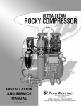
ULTRA CLEAN
LUBRICATED COMPRESSOR
INSTALLATION
AND SERVICE
MANUAL
Revised 4-15
TECH WEST INC.
Manufacturers of Dental Vacuum
and Air Systems
2625 N. Argyle Ave. • Fresno, CA 93727
(559) 291-1650 • (800) 428-7139 • FAX (559) 348-9677
ULTRA CLEAN
LUBRICATED COMPRESSOR
INSTALLATION AND SERVICE MANUAL
This manual is for the installation and service of Tech West’s Ultra Clean Lubricated Compressors.
CONTENTS
Installation
Location Requirements
Figure 1: Wire and Breaker Size
Installation Steps
Figure 2: Compressor Connections
Start Up
Maintenance
Figure 3: Checking and Changing the Oil
Figure 4: Replacing Oil Indicator Lens
Parts Breakdown
Dessicant Dryer Parts Breakdown
Coalescing Filter Parts Breakdown
Single Ultra Clean Lubricated Compressor Assembly
Dual Ultra Clean Lubricated Compressor Assembly
Triple Ultra Clean Lubricated Compressor Assembly
Compressor Wiring Diagram
3
3
4
5
6
6
7
7
8-11
12
13
14
15
16
17
TROUBLE SHOOTING
Single Compressor Trouble Shooting
Dual Compressor Trouble Shooting
Triple Compressor Trouble Shooting
Air Line Sizing Chart
Maintenance & Service / Notes Sheet
1
18-19
20-21
22-23
24
24-25
Maintenance & Service / Notes
2
ULTRA CLEAN LUBRICATED COMPRESSOR
INSTALLATION
1. ULTRA CLEAN LUBRICATED COMPRESSOR LOCATION REQUIREMENTS
The Ultra Clean Lubricated Compressor location should be level, accessible and well ventilated.
If the Ultra Clean Lubricated Compressor will be located in a confined space, provide adequate ventilation.
Electrical
(1)
Line voltage must be within the limits of Figure 1 below. (Install a “buck-boost
transformer” if line voltage is not between these values.) Circuit breaker switches
must be 20 - 30 amp depending on model and voltage necessary.
(2)
Local code may require you to provide one quick disconnect (safety switch) for the
compressor.
(3)
See Figure 1 below for breaker size and line voltage.
CAUTION - Voltage must be 110/128 v or motor damage may occur.
CAUTION - Voltage must be 208/240 v or motor damage may occur.
Figure 1: Recommended Wire and Breaker Size
Model
Voltage
Amperage
Wire Size
(Gauge)
Recommended
Breaker Size
7.2
13.6
12
12
20
20
14.4
12
20
21.6
10
30
Single Head Compressors
ACL2S2
ACL2S1
230
115
Dual Head Compressors
ACL4D2
230
Triple Head Compressors
ACL6T2
230
3
ULTRA CLEAN LUBRICATED COMPRESSOR
INSTALLATION
2
2. INSTALLATION STEPS
This dental Compressor should only be installed by qualified personnel. Should any questions arise
during the installation, call Tech West Technical Support between the hours of 7:00 a.m. to 4:00 p.m.
(Pacific Standard Time).
Place the compressor in a clean, dry, well ventilated area, on a solid, level surface. Consider sound
level and insulate as needed. Be sure that adequate ventilation is available as the compressor is air
cooled. Ambient temperature in the equipment room should be within the temperature range of 40
degrees Fahrenheit minimum to 100 degrees Fahrenheit maximum.
(a) Check the shipping carton for damage. This could detect damage to the unit which might
otherwise be overlooked. Remove cardboard shipping carton.
(b) Remove the Lubricated Compressor from its shipping skid. Inspect the unit for damage.
Lubricated Compressors are shipped bolted to a pallet. This pallet is intended for shipping
only and should be discarded.
(c) Remove installation kit attached to pallet. It should contain the following:
(4)
(1)
(1)
(1)
Isolation Feet
Alternate Air Hookup Hose
Bottle of Tech West Compressor Oil per Motor
5’ Flexible Air Hose
(d) Install isolation feet on tank legs.
(e) Remove shipping tape from spring-hinged oil filler cap(s).
(f) Install flexible hose to outlet on the compressor shut-off valve.
(g) Move compressor into place and level the motor platform.
(h) Install flexible hose to office air supply line.
(i) Install flexible hose to alternate fresh air supply.
(j) Wiring instructions:
1 Have all electrical connections made by qualified personnel only. All connections
should be in accordance with local codes.
2 Use the chart on page 1 to help determine the proper line and breaker size for
the unit that is being installed.
4
ULTRA CLEAN LUBRICATED COMPRESSOR
INSTALLATION
2
3. CONNECTIONS
Figure 2
Electrical Connection
to disconnect and
electrical panel
220 v
(110 v / 220 v ) on the
single models only.
Dryer Purge
Connection
Air Out
Connection to building
supply line.
Alternate Air
Connection
to fresh air supply.
5
ULTRA CLEAN LUBRICATED COMPRESSOR
INSTALLATION
4. START-UP STEPS
(a) Make sure the shut-off valve from the compressor tank is closed.
(b) Turn the breaker from the panel to the “ON” position.
(c) Turn power “ON” from the toggle switch on the compressor. Compressor should run quietly
and vibration free. The storage tank should start to build pressure.
(d) The compressor will run until the pressure gauge reads 100 psi. The compressor then will
automatically shut off and the dryer will purge with a quick blast of air.
(e) Using soapy water, check the compressor plumbing hook ups for leaks. Repair leaks if needed.
(f) Pressure test the entire plumbing system for leaks. Use the storage tank pressure gauge to
monitor a pressure drop. After the plumbing system has been pressurized for 30 minutes,
re-check the gauge for pressure drop. If there is a drop in pressure, find and repair all leaks
in the office plumbing.
AIR LEAKS ARE THE MAIN CAUSE OF COMPRESSOR FAILURES.
(g) Complete and mail in the warranty card for the compressor within ten days of installation.
5. PERIODIC SERVICING
WEEKLY SERVICING
(a) Check the oil level. Refer to figure 2. Use only Tech West oil specially formulated for Tech
West Compressors.
DO NOT OVERFILL. Add oil only when the oil level remains below the center line of the oil-level
sight glass after the compressor has been idle for at least 5 minutes.
(b) Empty condensate drain bucket under the dryer.
MONTHLY SERVICING
(a) Crack the drain petcock on the bottom of the storage tank to check for water and drain if needed.
(b) Check pump-up times.
(c) Check the moisture indicator to see that it is still “blue”. If it is pink it is time to service the air dryer.
YEARLY SERVICING
(a) Repeat all of the monthly servicing.
(b) Change oil (part # CO-100).
(c) Replace the dessicant air dryer (part # RDC-100).
(d) Replace the ultra clean coalescing filter. (part # CFEO-375). This keeps drying system efficient.
(e) Replace alternate air filter (part # TIF-100). Reduces oil consumption and lengthens
compressor life and efficiency.
(f) Replace the moisture indicator on the compressor (part # MI-100).
6
Figure 3: Checking and Changing the Oil
Instructions
Add oil to compressor through
oil filler spout. Do not overfill.
Keep filled to level as shown
below. Oil should be changed
annually or when oil becomes
discolored.
Oil Filler Spout
Check oil level with compressor
off and compressor sitting level.
Oil Drain Plug
Alternate
Drain Spout
OVER
OT
F
N
K
L
IL
DO
Indicator Lens
EE
P FU
Keep full to here.
LL
Figure 4: Replace Oil Indicator Lens
part #OSG-100
Important!
Drain oil from compressor head
before removing lens.
Note:
Replace only if damaged
or discolored.
Indicator Lens
Retaining Ring
7
Gasket
6
5
3
4
1
2
7
HEAD COVER AND FAN ASSEMBLY
KEY
PART NO.
DESCRIPTION
1
CCH-115
115 V COPELAND COMPRESSOR HEAD 1HP
1
2
CCH-230
230 V COPELAND COMPRESSOR HEAD 1 HP
1
3
CF-115
115 V COOLING FAN
1
4
CF-230
230 V COOLING FAN
1
5
CFS-100
COMPRESSOR FAN SHROUD
1
6
CFG-100
FINGER GUARD
1
7
OSG-100
OIL SIGHT GLASS
1
8
UNIT
Figure 4: AIR COMPRESSOR STARTER ASSEMBLY
4
5
1
3
2
6
9
7
8
10
ULTRA CLEAN AIR COMPRESSOR STARTER ASSEMBLY
KEY
PART NO.
DESCRIPTION
1
CRA-115
115 V CAP AND RELAY ASSEMBLY, COMPLETE
1
2
CRA-208
208-230 V CAP AND RELAY ASSEMBLY, COMPLETE
1
3
CRA-230
230 V ONLY CAP AND RELAY ASSEMBLY, COMPLETE
1
4
PR-115
115 V POTENTIAL RELAY
1
5
PR-208
208-230 V ONLY POTENTIAL RELAY
1
6
RCC-115
115 V RUN CAPACITOR
1
7
RCC-208
208-230 V RUN CAPACITOR
1
8
RCC-230
230 V ONLY RUN CAPACITOR
1
9
SCC-115
115 V START CAPACITOR
1
10
SCC-230
208-230 V / 230 V ONLY START CAPACITOR
1
9
UNIT
SINGLE COMPRESSOR CONFIGURATION
2
7
5
8
4
30
40 50
1
60
7
20
8
10
0
psi
90
100
2
3
DUAL AND TRIPLE
COMPRESSOR CONFIGURATION
5
6
4
7
50 60
0
1
70
0
80
20
90
100
3
10
0
GAUGE AND CUT-OFF ASSEMBLY
KEY
PART NO.
1
CPG-250
2
DESCRIPTION
UNIT
COMPRESSOR GAUGE
1
BV-250
1/4” BALL VALVE
1
3
MI-100
MOISTURE INDICATOR
1
4
FA-4-4
1/4” FLARE HOSE FITTING
1
5
BN-250-CL
1/4” BRASS CLOSE NIPPLE
1
6
BT-250
1/4” BRASS TEE
1
7
BSE-250
1/4” BRASS ELBOW
1
8
BPC-4
1/4” BRASS CROSS
1
10
3
5
6
2
4
1
3
7
REAR VIEW ASSEMBLY AND PARTS LIST
KEY
PART NO.
1
CV-375MF-100
2
CPT-100
3
CV-375D-100
4
HA-12-250
5
DESCRIPTION
UNIT
3/8 CHECK VALVE MALE TO FEMALE CONNECTION
1
COMPRESSOR PURGE TANK
1
3/8 CHECK VALVE
1-3
1/4 HOSE ASSEMBLY - 12” LONG
1
DPC-1
DRYER PRE COOLER SINGLE COMPRESSOR
1
6
DPC-2
DRYER PRE COOLER DUAL & TRIPLE COMPRESSOR
1
7
RFV-100
RUBBER MOUNTING FEET
4
11
9
8
7
12
DSV-230
AS-500
RDC-100
MV-250
SN-250-CL
FE-4-6
BV-250
BT-250
PFH-375
MSD-100
MSD-200
CV-250D
3
4
5
6
7
8
9
10
11
12
13
9
2
6
DSV-115
13
1
1
10
1/4 CHECK VALVE
ACTIVATED ALUMINA 1 LB
MOLECULAR-SIEVE 1 LB
1
2LBS
2LBS
PER FOOT
2
1
1
3
1
1
1
1
1
UNIT
3
CLEAR DRAIN HOSE
BRASS TEE 1/4
BALL VALVE 1/4
FLAIR FITTING 1/4 X 3/8
STAINLESS STEEL NIPPLE 1/4
METERING VALVE
REPLACEMENT DESSICANT TANK
1/2 FILTER ASSY
230V PURGE SOLENOID VALVE
115V PURGE SOLENOID VALVE
DESCRIPTION
INSIDE
TANK
ELEMENT
PART NO.
11 12
KEY
5
NEW DESICCANT AIR DRYER ASSEMBLY
4
2
1
3
2
FILTER ASSEMBLY
KEY
PART NO.
1
CFAO-375
DESCRIPTION
2
CFEO-375
COALESCING FILTER ELEMENT 3/8
1
3
CFBP-375
COALESCING FILTER BOWL
1
COALESCING FILTER ASSEMBLY 3/8
13
UNIT
1
7
6
14 15
10
2
9
3
17
5
11
18
4
1
16
13
12
SINGLE ULTRA CLEAN LUBRICATED COMPRESSOR
KEY
PART NO.
DESCRIPTION
1
SBHA-21-375
2
SBHA-7.5-375E
STEEL BRAID HOSE ASSEMBLY
1
3
SBHA-21-375E
STEEL BRAID HOSE ASSEMBLY
1
STEEL BRAID HOSE ASSEMBLY
UNIT
1
4
FPH-375
PURGE FLEX HOSE CLEAR
5
ZZACS61
1/4 HOSE ASSEMBLY
PER FT
6
PFT-500
7
CFAO-375
COALESCING FILTER 3/8
1
9
DPB-100
DRYER PURGE BUCKET
1
1
POLY FLO TUBE 1/2
PER FT
10
CPT-100
COMPRESSOR PURGE TANK
1
11
RDC-100
REPLACEMENT DESICCANT CARTRIDGE
1
12
DSV-115
1/4 CHECK VALVE
1
13
DSV-230
PURGE VALVE SOLENOID VALVE 230V
1
14
CCH-115
LUBRICATED COMPRESSOR HEAD 115V
1
15
CCH-230
LUBRICATED COMPRESSOR HEAD 230V
1
16
RFV-100
RUBBER MOUNTING FEET
4
17
PSC-3
PRESSURE SWITCH
1
18
POVA-100
SAFETY POP OFF VALVE
1
14
7
15
6
3
14
12
10
2
17
9
5
18
11
4
13
1
16
DUAL ULTRA CLEAN LUBRICATED COMPRESSOR
KEY
PART NO.
DESCRIPTION
UNIT
1
SBHA-21-375
STEEL BRAID HOSE ASSEMBLY
1
2
SBHA-10-375E
STEEL BRAID HOSE ASSEMBLY
1
3
SBHA-9-375E
STEEL BRAID HOSE ASSEMBLY
1
4
FPH-375
PURGE FLEX HOSE CLEAR
5
ZZACS61
1/4 HOSE ASSEMBLY
PER FT
1
6
PFT-500
7
CFAO-375
COALESCING FILTER 3/8
POLY FLO TUBE 1/2
PER FT
1
9
DPB-100
DRYER PURGE BUCKET
1
10
CPT-100
COMPRESSOR PURGE TANK
1
11
RDC-100
REPLACEMENT DESICCANT CARTRIDGE
1
3/8 CHECK VALVE
2
PURGE VALVE SOLENOID VALVE 230V
1
STEEL BRAID HOSE ASSEMBLY
2
12
CV-375D-100
13
DSV-230
14
SBHA-18-375
15
CCH-230
LUBRICATED COMPRESSOR HEAD 230V
2
16
RFV-100
RUBBER MOUNTING FEET
4
PRESSURE SWITCH
1
SAFETY POP OFF VALVE
1
17
PSC-3
18
POVA-100
15
15
7
6
3
12
14
2
10
17
5
9
18
11
4
1
13
16
TRIPLE ULTRA CLEAN LUBRICATED COMPRESSOR
KEY
PART NO.
DESCRIPTION
UNIT
1
SBHA-21-375
STEEL BRAID HOSE ASSEMBLY
1
2
SBHA-10-375E
STEEL BRAID HOSE ASSEMBLY
1
3
SBHA-9-375E
STEEL BRAID HOSE ASSEMBLY
1
4
FPH-375
PURGE FLEX HOSE CLEAR
5
ZZACS61
POLY FLO TUBE 1/4
PER FT
1
POLY FLO TUBE 1/2
PER FT
6
PFT-500
7
CFAO-375
COALESCING FILTER 3/8
1
9
DPB-100
DRYER PURGE BUCKET
1
10
CPT-100
COMPRESSOR PURGE TANK
1
11
RDC-100
REPLACEMENT DESICCANT CARTRIDGE
1
3/8 CHECK VALVE
3
PURGE VALVE SOLENOID VALVE 230V
1
STEEL BRAID HOSE ASSEMBLY
3
12
CV-375D-100
13
DSV-230
14
SBHA-18-375
15
CCH-230
LUBRICATED COMPRESSOR HEAD 230V
3
16
RFV-100
RUBBER MOUNTING FEET
4
PRESSURE SWITCH
1
SAFETY POP OFF VALVE
1
17
PSC-3
18
POVA-100
16
Figure 5: Compressor Wiring Diagram
17
18
GO ON TO
THE NEXT
PAGE.
Defective
head,
contact
Tech West.
Replace
intake
filter.
Clean
or
replace.
NO
YES
NO
DOES AIR
COMPRESSOR
RUN?
Is there sufficient
pressure build-up
with head
discharge line
removed?
NO
Is intake filter
clogged?
YES
Does purge
valve seal while
running?
YES
YES
Check voltage
supplied to the
compressor.
YES
Does compressor run
for a few
seconds, “chugs”, then
stops?
Contact
Tech West.
Locate
and repair.
NO
NO
YES
Examine the check
valve and the
purge valve for
leaks.
YES
Does air leak
from unloader
valve until unit
cycles again?
NO
Are there leaks in
compressor or in
office piping system?
NO
Does compressor pressurize from 80 to 100
psi in less than 1
minute with no air
being used?
NO
Contact
Tech West.
1. Ensure that
unloader valve
& pressure
switch close on
pump-up, &
open on purge
cycle.
2. Ensure that
drain line is not
clogged.
NO
YES
Does compressor run
too hot or too
frequent?
YES
Does
unloader
valve system
function
properly?
YES
Is the moisture
indicator pink?
YES
Contact
Tech West.
NO
Does compressor run
too hot or too
frequent?
YES
Is head
level?
YES
Is there excessive
oil usage?
NO
1. Locate and repair
leaks.
2. Ventilate if room is
above
100 deg. F.
3. Contact compressor
may be undersized.
Level
head.
NO
Single Ultra Clean Lubricated Compressor Diagram
YES
Does compressor
cycle with no air
being used?
NOTE: Close
shut off valve.
Pump up tank to
100 psi. If pressure is maintained for 15-20
min., leak is in
office lines.
YES
Single Ultra Clean Lubricated Compressor
Trouble Shooting Chart
19
Install
Tech West
transformer.
Blockage in
air line.
Locate &
repair.
Increase
room temp.
GO ON TO
THE NEXT
PAGE
NO
YES
NOTE: Voltage
should be + or 10% of rating.
Is there
sufficient
voltage at
disconnect
box?
NO
Does head
run with discharge line
disconnected?
YES
YES
Replace
defective
thermal
protector.
Replace
defective
capacitors.
NO
NO
Contact Tech West.
Head may be frozen.
YES
Is there continuity
across the thermal
protector?
YES
Is there resistance
rise across the
capacitors?
YES
Is there continuity
across terminal 2 & 5
or potential relay?
NO
Does motor run
after tapping
capacitor/relay box
or does start
capacitor feel hot?
YES
Is room
temperature
above 40o
fahr.?
Replace
defective
potential
relay
YES
YES
NO
Is there sufficient voltage at motor terminals
when motor tries to
start?
COMPRESSOR
DOES NOT RUN
OR RUNS FOR
ONLY A FEW
SECONDS.
NOTE:
Short capacitor leads.
Check resistance
rise. If no resistance
rise, replace.
NOTE:
1. Tape relay box.
If starts, relay is bad.
2. Check for continuity
across 2 & 5.
Replace if none.
NO
CHECK FOR:
1. Broken or loose
wire.
2. Defective pressure
switch.
3. Defective ON/OFF
switch.
4. Excessive voltage
drop across power
lines.
Single Ultra Clean Lubricated Compressor
Wiring Diagram
20
GO ON TO
THE NEXT
PAGE.
Locate
and repair.
Defective
head,
contact
Tech West.
Replace
intake
filter.
Clean
or
replace.
YES
NO
YES
NO
DOES AIR
COMPRESSOR
RUN?
Is there a
blockage in
the air lines?
YES
Is there sufficient
pressure build-up
with head
discharge line
removed?
NO
Is intake filter
clogged?
YES
Does purge
valve seal while
running?
YES
NO
Check voltage
supplied to the
compressor.
YES
Does compressor run
for a few
seconds, “chugs”, then
stops?
Contact
Tech West.
Locate
and repair.
NO
NO
YES
Examine the check
valve and the
purge valve for
leaks.
YES
Does air leak
from unloader
valve until unit
cycles again?
NO
Are there leaks in
compressor or in
office piping system?
NO
Does compressor pressurize from 80 to 100
psi in less than 1
minute with no air
being used?
NO
Run unit in manual
purge mode for
one week. If
indicator still wet,
replace desiccant.
1. Ensure that
unloader valve
& pressure
switch close on
pump-up, &
open on purge
cycle.
2. Ensure that
drain line is not
clogged.
NO
YES
Does compressor run
too hot or too
frequent?
YES
Does
unloader
valve system
function
properly?
YES
Is the moisture
indicator pink?
YES
Contact
Tech West.
NO
Does compressor run
too hot or too
frequent?
YES
Is head
level?
YES
Is there excessive
oil usage?
NO
1. Locate and repair
leaks.
2. Ventilate if room is
above
100 deg. F.
3. Contact compressor
may be undersized.
Level
head.
NO
Dual Ultra Clean Lubricated Compressor Diagram
YES
Does compressor
cycle with no air
being used?
Note: Close
shut off valve.
Pump up tank to
100 psi. If pressure is maintained for 15-20
min., leak is in
office lines.
YES
Dual Ultra Clean Lubricated Compressor
Trouble Shooting Chart
21
Install
Tech West
transformer
Blockage in
air line.
Locate &
repair
Increase
room temp.
GO ON TO
THE NEXT
PAGE
NO
YES
NOTE: Voltage
should be + or 10% of rating.
Is there
sufficient
voltage at
disconnect
box?
NO
Does head
run with discharge line
disconnected?
YES
YES
Replace
defective
thermal
protector
Replace
defective
capacitors
NO
NO
Contact Tech West.
Head may be frozen.
YES
Is there continuity
across the thermal
protector?
YES
Is there resistance
rise across the
capacitors?
YES
Is there continuity
across terminal 2 & 5
or potential relay?
NO
Does motor run
after tapping
capacitor/relay box
or does start
capacitor feel hot?
YES
Is room
temperature
above 40o
fahr.?
Replace
defective
potential
relay
YES
YES
NO
Is there sufficient
voltage at motor
terminals when
motor tries to start?
COMPRESSOR
DOES NOT RUN
OR RUNS FOR
ONLY A FEW
SECONDS
NOTE:
Short capacitor leads.
Check resistance
rise. If no resistance
rise, replace.
NOTE:
1. Tape relay box.
If starts, relay is bad.
2. Check for continuity
across 2 & 5.
Replace if none.
NO
CHECK FOR:
1. Broken or loose
wire.
2. Defective pressure
switch.
3. Defective ON/OFF
switch.
4. Excessive voltage
drop across power
lines.
Dual Ultra Clean Lubricated Compressor
Wiring Diagram
22
GO ON TO
THE NEXT
PAGE.
Locate
and repair.
Defective
head,
contact
Tech West.
Replace
intake
filter.
Clean
or
replace.
YES
NO
YES
NO
DOES AIR
COMPRESSOR
RUN?
Is there a
blockage in
the air lines?
YES
Is there sufficient
pressure build-up
with head
discharge line
removed?
NO
Is intake filter
clogged?
YES
Does purge
valve seal while
running?
YES
NOTE:
Inspect check
valves (L) for
build-up that
can clog and
restrict air
flow.
NO
Check voltage
supplied to the
compressor.
YES
Does compressor run
for a few
seconds, “chugs”, then
stops?
Contact
Tech West.
Locate
and repair.
NO
NO
YES
Examine the check
valve and the
purge valve for
leaks.
YES
Does air leak
from unloader
valve until unit
cycles again?
NO
Are there leaks in
compressor or in
office piping system?
NO
Does compressor pressurize from 80 to 100
psi in less than 1
minute with no air
being used?
NO
Run unit in manual
purge mode for
one week. If
indicator still wet,
replace desiccant.
1. Ensure that
unloader valve
& pressure
switch close on
pump-up, &
open on purge
cycle.
2. Ensure that
drain line is not
clogged.
NO
YES
Does compressor run
too hot or too
frequent?
YES
Does
unloader
valve system
function
properly?
YES
Is the moisture
indicator pink?
YES
Contact
Tech West.
NO
Does compressor run
too hot or too
frequent?
YES
Is head
level?
YES
Is there excessive
oil usage?
NO
1. Locate and repair
leaks.
2. Ventilate if room is
above
100 deg. F.
3. Contact compressor
may be undersized.
Level
head.
NO
Triple Ultra Clean Lubricated Compressor Diagram
YES
Does compressor
cycle with no air
being used?
Note: Close
shut off valve.
Pump up tank to
100 psi. If pressure is maintained for 15-20
min., leak is in
office lines.
YES
Triple Ultra Clean Lubricated Compressor
Trouble Shooting Chart
23
Install
Tech West
transformer
Blockage in
air line.
Locate &
repair
Increase
room temp.
GO ON TO
THE NEXT
PAGE
NO
YES
NO
NOTE: Voltage
should be + or 10% of rating.
Is there
sufficient
voltage at
disconnect
box?
NO
Does head
run with discharge line
disconnected?
YES
YES
Replace
defective
thermal
protector
Replace
defective
capacitors
NO
NO
Contact Tech West.
Head may be frozen.
YES
Is there continuity
across the thermal
protector?
YES
Is there resistance
rise across the
capacitors?
YES
Is there continuity
across terminal 2 & 5
or potential relay?
NO
Does motor run
after tapping
capacitor/relay box
or does start
capacitor feel hot?
YES
Is room
temperature
above 40o
fahr.?
Replace
defective
potential
relay
YES
Is there sufficient
voltage at motor
terminals when
motor tries to start?
YES
COMPRESSOR
DOES NOT RUN
OR RUNS FOR
ONLY A FEW
SECONDS
NOTE:
Short capacitor leads.
Check resistance
rise. If no resistance
rise, replace.
NOTE:
1. Tape relay box.
If starts, relay is bad.
2. Check for continuity
across 2 & 5.
Replace if none.
NO
CHECK FOR:
1. Broken or loose
wire.
2. Defective pressure
switch.
3. Defective ON/OFF
switch.
4. Excessive voltage
drop across power
lines.
Triple Ultra Clean Lubricated Compressor
Wiring Diagram
Maintenance & Service / Notes
24
Maintenance & Service / Notes
25
TECH WEST INC.
Manufacturers of Dental Vacuum
and Air Systems
2625 N. Argyle Ave. • Fresno, CA 93727
(559) 291-1650 • (800) 428-7139 • FAX (559) 348-9677