1
VR-32 Regulator and CL-4C Control
The Channel #1 baud rate is selectable at 300, 1200, 2400,
and 4800 BAUD. However, to permit communications with the
Cooper Power Systems Data Reader, the Channel 1 baud rate
is set at the factory to 4800 BAUD.
Communications Channel #2 is dedicated to the real-time
digital communications interface. Like other advanced controls
developed by Cooper Power Systems, the CL-4C Control utilizes a point structure data base. This permits all parameters
to be read, changed, or reset (as appropriate) through the
SCADA system, there by allowing the user to perform virtually
any function remotely which might otherwise be done locally at
the regulator front panel. All Cooper Power Systems advanced
controls employ the same protocol for communications to the
“outside world.” This standard protocol is defined as DATA
2200, which is an 8-bit, character-oriented, asynchronous format, and is not proprietary.
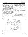
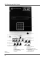
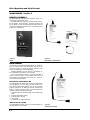
The physical implementation of digital communications to
the CL-4C is accomplished through an optional two board set
consisting of a protocol converter module and a fiber optic
transmitter/receiver module. The protocol converter mounts
directly above the CL-4C main circuit board set (on the front
panel) and plugs directly into it. Its primary function is to provide the “outside world” with a suitable communications interface to the CL-4C main control unit. The system is designed
such that this module can be easily added in the field.
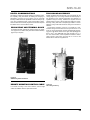
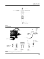
The fiber optic transmitter/receiver module mounts on the
back panel of the control enclosure, and also can be field
installed. It is connected to the protocol converter module
through an eight conductor cable, and connects into the
SCADA system via two ST bayonet style fiber optic transmitter
and receiver connectors. The fiber optic communications
medium was chosen because it has demonstrated clear superiority to traditional RS232 cabling in terms of electrical isolation and surge protection. To interface to an RTU RS232 port,
a fiber optic-to-RS232 converter is used at the RTU. This
device is also available from Cooper Power Systems.
Separate documents are available to describe the user
information for these communications interface modules.
When a communications system is in place and active, it
can perform all functions which the operator may perform at
the front panel. To prevent the SCADA system from conflicting
with local operator commands, several measures have been
taken:
1) The SCADA system may be completely disabled by an
ON/OFF switch located on the fiber optic module, on the
control back panel. When the switch is OFF, the system is
electrically disconnected from the CL-4C Control such that
no READ, WRITE, or RESET commands can reach the
control. However, if the control is in a loop system, the loop
is maintained even with the switch OFF. NOTE: IF THE
SCADA SYSTEM HAD PLACED THE CONTROL IN THE
“INHIBIT TAP CHANGE” MODE, AUTOMATIC OPERATION WILL REMAIN INHIBITED UNLESS THE OPERATOR ACCESSES FUNCTION CODE 69 AND CHANGES
THE STATE OF THIS CODE (FROM 1 To 0). SEE FUNCTION CODE 69 DESCRIPTION ON PAGE 2-19.
2) The control switch on the CL-4C front panel must be placed
in the AUTO/REMOTE position for remote tap change
commands to be performed. If this switch is in either the
OFF or MANUAL position, no tap changes can occur, but
normal READ, WRITE, and RESET commands from the
SCADA system can be performed.
3) When the local operator enters any security code (level
1,2, or 3), the SCADA system is prevented from WRITING
or RESETTING any CL-4C parameter. However, SCADA
READ commands can occur under these conditions. When
2-29
mends can occur under these conditions. When the security
level is set back to “0,” full SCADA control resumes. The security level is reset to “0” by either (1 ) turning the CL-4C display
off, or (2) after 30 minutes to no keypad activity, the display
automatically shuts off, and the security is set to “0” at that
time.
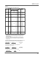
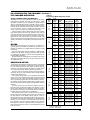
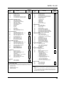
The specific communications parameters are listed in function
codes 60-69, and are described more fully in the function code
section beginning on page 2-17. NOTE: When any of the function codes affecting communications are changed via the
keypad, the power to the CL-4C Control must be turned off,
and then back on, to force these “new” communications
parameters to be loaded into the optional protocol converter
module.