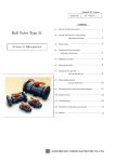
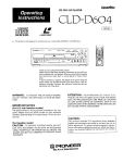
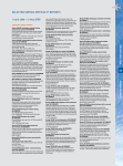
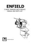
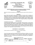
1
JAGUAR
SERVICE BULLETIN
Number F . l.
Section Gearbox and
Overdrive
Sheet l (of l)
Date October, 1961
·..
GEARBOX CONSTANT PINION OIL SEAL
Models affected
2.4 litre Mark 2
3.4 litre :U::ark 2
3.8 litre :U::ark 2
Commencing Gearbox Numbers
)
)
)
"E" Type
GBN.55050
E.B.868
On cars with the above gearbox numbers and onwards, a flangedtype constant pinion oil seal (Part Number C.l8739) is fitted to the
re ce ss in the clutch housing. The i n terchangeab i lity is not aff ec ted
but it should be noted that a chamfer of approximately 1/16 11 (1.6 mm)
should be made on the edge of the recess to provide a "lead-in" fo r
the seal. The o il seal should also be well lubricated before pres sing
into the recess.
Spares Bulletin Numbe r •D .5 refers.
Amendment to Service Bulletin Numbers FF.3 and FF.4 .
Under commencing chassis numbers in the above bulletins insert
the fol,lowing:-
2 . 4 litre Yark 2
R.H. Drive
L.H. Drive
109308
1 2 6499
Jaguar Cars Limited 2005
.......
~
'?~
JAGUAR
SERVICE
BULLETiN
Number F .1. )..
Section Gearbox and
Overdrive
Sheet 1 (of 1)
Date April, 1 962
WARRANTY - LAYCOCK CNERDRIVE UNIT
(Home Trade only)
If trouble is experienced with an overdrive unit during the
period of warranty (12 months) the unit should on no account be
dismantled as the manufacturers are consequently unable to test and
examine the parts in their original condition.
Only external checks, such as valve setting and hydraulic
pressure testing should, therefore, be undertaken.
If, on dismantling a low mileage unit which is just outside
the warranty period, it is found subsequent to examination that an outof-warranty claim may be justified, the unit must be completely reassembled and returned to t hese works in accordance with the normal
warranty procedure.
No claim will be considered if the unit is
incomplete.
·l
;
1
i
. ..
....4 ;.
~
Jaguar Cars Limited 2005
.J
.•
, v; ~
JAGUAR
SERVICE
Number
Section
Sheet
Date
BULLETIN
F .6.
Gearbox and Overdrive
of 1 )
September, 1963.
1 (
BENCH TESTING THE OVERDRIVE SOLENOID.
(All Models)
It should be noted that on no account must a solenoid be
energised before fitting to the car.
As the solenoid plunger has no load to carry, t he impact
of it opening the contact points will be sufficient to bend the
contact arm, preventing the points from opening.
Jaguar Cars Limited 2005
JAGUAR
SERVICE
BULLETIN
Number F. 7.
Section Gearbox and Overdrive.
Sheet 1 ( of 1
Date January, 1964.
STICKING IN 1ST GEAR.
(AH
l!i)'J
ett •ili!ESI• ged! l!ox inodels)
If difficulty is experienced with sticking in first gear
the following procedure should be adopted.
Remove the console trim and gearbox tunnel cover, then the
top cover of the gearbox. I t may then be necessary to use two levers
to ease the 1st speed gear for·:.Jard on the 2nd speed synchro-sleeve .
Ignore the slight damage which may have occurred to the stop pin on the
2nd speed synchro-sleeve.
With the gearbox top cover on th~ bench, remove the selector
housing by taking off the four retaining nuts. This will expose the
three plunger springs which shodd be removed together with the plunger
and balls (and shims i f any). Wi t hdraw the centre welch washer at each
end of the top cover by piercing and prising as necessary. Then
remove the wired dowel pins retaining the stop and the change speed
fork on the centre striking rod so that this may be driven fo~vard a
sufficient amount to fit a washe r~" (19 mm) outside diameter and~~
(12.7 mn) inner diameter, thickness 1/16" (1.6 rnm) onto the rod behind
the change speed fork. Ensure that the washer clears the sel ectors on
the other striking rods. (See illustration overleaf).
Replace the s triking rod, change speed fork and stop and
refit the two dowel pins wirJng t hem up as before. Fit new welch
washers either end of the top cover then repl ace the three balls,
plungers, springs and shims (if fitted) in the respective hol es . Use
a new gasket when replac ing the selector housing and fit a new gasket
on the gearbox case top f ace . Place the gearbox in neutral offer up
the top cover noting that it i s located by two dowels and secure in
position with the ten setscrews and spring washers (two long screws at
rear and two short screws at front). Replace the tunnel cover and trim.
Jaguar Cars Limited 2005
Jaguar Cars Limited 2005
JAGUAR
SERVICE
BULLETIN
Number F.8.
Section Gearbox and OVerdrive.
Sheet 1 ( of 1 )
Date March, 1964.
GEARBOX NEEDLE ROLLERS.
(All models)
The needle rollers on which the countershaft and 2nd and
3rd speed gears rotate are now graded according to their diameter and
rollers of one grade only must be used in individual gear assemblies.
The part numbers of the individual grades are as follows:Part No.
Description.
No. off.
C.918/1
+.0001"
Needle Roller, on Countershaft (3 nm -.OOOO")
C.91 8/2
Needle Roller, on Countershaft ( 3 nm
C.918/3
Needle Roller, on Countershaft (3 mm -.00<)2")
C.1850/1
Needle Roller, in 2nd and 3rd Speed Gears
+ 0001"
82
Needle Roller, in 2nd and 3rd Speed Gears
82
~
+.0000''
-.ocx:n")
58
-.0001"
(3.5nun
c. 1850/2
58
58
-:oooo")
+ 0000"
(3.Smn _: 0001 .,
c. 1850/3
Needle Roller, ln 2nd and 3rd Speed Gears
- 0001 11
( 3 .smm
82
-:oooz")
Spares Bulletin No. 0.15 refers.
Jaguar Cars Limited 2005
JAGUAR
SERVICE
BULLETIN
Number F .13.
Section Gearbox and Overdrive.
I
Sheet 1 ( of 2 )
Date September, 1965.
4 SPEED ALL SYNCHROMESH GEARBOX.
Service Bulletin F.9 refers to the 4 speed all synchromesh gearbox as being optional extra on the 3.4/3.8 'S' Models.
This gearbox has now become standard equipment on all 'S' models and
also on the 2.4, 3.4 and 3.8 Mark 2 models.
The chassis introduction numbers of the Mark 2 models are
given below:
Model affected.
Commencing chassis numbers.
R.H.Drive.
2..4 litre Mark 2
119200
plus
11 9149 to 11 9151
127822
169341
169285
180188
234125
plus
234079 to 234089
224150
3.4 litre Mark 2
and
3.8 litre Mark 2
L.H.DrJ_ve.
The engine idling speeds and recommended lubricants are
as stated on Service Bulletin F.9.
DISMANTLING (Mark 2 Models)
Removal of Clutch Housing.
Detach the springs and remove the carbon thrust bearing.
Unscrew the two nuts and remove the clutch slave cylinder.
Remove the allen screw, push out the fulcrum pin and
detach the clutch fork.
Tap back the locking tabs and break the locking wire and
remove the eight setscrews.
Detach the clutch housing.
/cont'd .......... .
Jaguar Cars Limited 2005
Removal of Top Cover.
Remove the ten setscrews and lift off the lid.
Removal of Overdrive. (Overdrive Models)
Remove the six nuts securing the overdrive to the
extension, that is two nuts at each side and the two lowermost nuts
of the four on the long studs. Withdraw the overdrive.
Unscrew the seven setscrews securing the extension to
the rear of the gearbox.
Withdraw the cam, tap back the tab washer and unscrew
the large nut.
Removal of Countet·shaft.
Remove the fibre plug from the front end of the countershaft.
Drive out the countershaft from the front of the casing.
Important:
Ensure that the rear washe r (pegged to casing) drops down
in a c lockwise dir ection looking from the rear to avoid
trapping the washer with the reverse gear whe n driving
the mainshaft forward (see illustration). This is
effected by rocking the gearbox casing and moving the
reverse lever backwa rds and f orwards.
Removal of Constant Pinion Shaf t.
With the aid of two tyre levers ease the constant
pinion shaft forward until it can be withdrawn.
Removal of Mainshaft.
Tap the mainshaft through the rear bearing ensuring that
the reverse gear is kept tight against the first gear.
After removal of the rear bearing from the casing fit
a hose clip to the mainshaft to prevent the reverse gear from sliding
off.
Slacken the reverse lever bolt until the lever can be moved
to the rear.
Lift out the mainshaft forward and upward.
Lift out the countershaft gear unit and collect the
needle bearings.
/cont' d ••••••••••
Jaguar Cars Limited 2005
•
Service Bulletin No. F.13.
continued
Sheet 2 ( of 2 )
Withdraw the reverse idler shaft and lift ouL the
gear.
Reassembly.
Reassembly is the reverse of the dismantling procedure
but the following points should be noted.
•
1.
Attach the rear thrust washer to the casing with greasf
and retain in position with the countershaft.
2.
Fit the needle rollers to the countershaft gea r unit
with grease.
3.
To mesh the countershaft ge ar unit with the ma inshaft
turn the gearbox upside down and enter the countershaft
taking care not to displace the needle rollers.
When refitting the overdrive a lign the splines in t he
usual way, push the overdrive on as f ar as possible and rotate the
overdrive flange until the oil pump plunger engages the cam on the
main shaft.
Spares Bulletin No. D.26 refers.
Jaguar Cars Limited 2005
JAGUAR
SERVICE BULLETIN
Number F.14
Section Gearbox and Overdrive
Page 1 of 3
Date September, 1 966
CXIdPACT CN'ERDRIVE UNIT
Models affected
Overdrive Unit number
4.2 Mark 10
3.4/3.8 "S" Models
3.4/3 .8 Mark 2
3.4 Mark 2
2b/60552
~8/60572
28/61740
28/61743
In isolated instances "slipping in reve rse" and " sticking in
overdrive" conditions have occurred in the above units.
To overcome these faults a modification kit, Jaguar Part No.
11301 (Laycock Part No . 65980) is now available and consists of the
fol l owing items:Jaguar Part No.
11303
11304
10968
C.5965
;;==:i~
Item
Laycock Part No.
Clutch return spring
(Set of 6 )
Packing washer f or accumulator
spring (1)
Ope r ating valve ( 1)
TabWasher (4)
65966
62023
60686
65300
Fitting Instructions
Remove the engine and gearbox as a unit from the car as detai l ed
in Section "B" of the appropriate Service Manual.
Remove six nuts and lock:wash ers and detach the ove rdrive unit from
the adaptor plate attached to the rear end of the gearbox.
Release the tab washers and remove four nuts, tab washers and the
two operating piston bridge pieces.
Release the solenoid securing screws to allow the front casi ng of
the unit to be removed.
/ cont' d •••
Jaguar Cars Limited 2005
Bulletin F. 14
September, 1966
Page 2 of 3
Remove the four nuts and washers and separate the front and rear
casings.
Lift out the clutch sliding member complete with thrust ring,
bearing and sunwheel.
Examine the clutch linings on the sliding member for signs of
excessive wear or charring.
If wear is apparent, renew the clutch sliding member, Jaguar Part
No. 10848 (Laycock Part No. 65920) and the thrust bearing, Jaguar Part
No. C.5968 (Laycock Part No. 65024).
The unit can now be re-assembled by reversing the dismantling
procedure.
Fit the new clutch return springs, contained in the
modification kit and painted red on the end coil.
Unscrew the main operating valve plug, located on the bottom of
thz unit nn the same side as the solenoid.
•
Remove the spring, plunger and ball.
Remov(~ the operating valve by i nserti ng a piece of stiff wire in
the central bore and withdrawing downwards.
Insert the new valve contained in the. kit, ensuring that the
end engages on the f l at of the small operating lever on
the operating shaft.
hemispheri~al
Refit the ball, plunger
~nd
spring.
kefit the plug and tighten fully, ensure when fitting that the
copper washer is correctly located.
Check the solenoid setting as detailed on Page F. 2~ of the 3 .4/3 .8
5 11 model Service Manual, Page F.28 of the 4.2 Mark 10 Service Manual
and Page F.31 of the Mark 2 Service Manual.
11
Invert the unit and withdraw the accumulator spring plug.
Care
must be taken not to lose any packing washers which may be fitted between
the spring and the plug.
Place the packing washer 11304 (62023) contained in the modification
kit in the base of the plug.
This is additional to any which may already
be fitted.
/cont'd •••
Jaguar Cars Limited 2005
•
Bulletin F .14
September, 1966
Page 3 of 3
Refit the plug and sealing washer.
Note:
The addition of packing washer 11304 ( 62023) will r aise the
hydraulic pressure to Unit 28/60552 - 540/560 P.S.I.
Unit 28/60572 - 490/510 P.S.I.
Unit 28/61740- 490/510 P.S.I.
Unit 28/61743 - 480/500 P.S.I.
Reassemble the unit to the engine aLd refit to the car.
The modifications referred to in this Bulletin have been introduced
in production build by Laycock Engineering Ltd., commencing with Unit 28/60552/1342 - 4.2 Mar k 10
Unit 28/60572/8407 - 3.4-3 .8 "S" t ype
Unit 28/61 740/2647 - 3.4-3.8 Mar k 2
Unit 28/61743/1116 - 2.4Mark 2
Spares Bulletin D.30 r ef ers .
Jaguar Cars Limited 2005
JAGUAR
SERVICE
BULLETIN
Number F .1 5
Section Gearbox and Overdrive
Page 1 of 1
Date December. 1 966
GEAR LEVER RETAIJ\'Ji\(; WASHER
(Standard and Overdrive Transmission)
Models affected
L.4 Litre Mark 2)
3,4 Litre Mark 2)
3,8 Litre Mark 2)
Commencing Gearbox Nwnbers
3.4 Litre 'S' Type)
3.8 Litre 'S' Type)
4.2 Mark 10
4.2 IE' Type F .H .C.
4.2 'E' Type Open
4.2 'E' Type 2+2
JC:'-1.3467
JBN .81 Ll
JZI\.923
EJ.7920
EJ. 7920
EJS.7920
Isolated instance::s have occ.HTed where the bonded rubber bush at t he
bottom of the gear lever has allowed tne lever to become detached.
To prevent this, a di s)-led retaining washer has now been fitt.ed
between the bush and lever securing nut, and the above serial numbers
record the comnencernent of the modification.
The retaining washer may, if desired, be fitted to gearboxes prior
to the above numbers as follows:Remove Lhe console and gear lever grommet as dct.ailed in the
appropriute Service Manual.
On -1.2 'E' Type cars it wi.ll also be necessary to remove the tunnel
cover.
Remove the retaining nut at the base of the lever.
Fit the washer with the hollow race to the bonded rubber bush and
refit the retaining nut.
Refit the gear lever groJ!Jllet and console.
Reseal the tunnel cover on 1.2 'E' Type cars with a good quality
sealing compound to prevent the entry of water.
Spares Bulletin D.31 refers.
Jaguar Cars Limited 2005
JAGUAR
SERVICE BULLETIN
Number F .. 16
Section Gearbox anct Overdrive
Sheet 1 of 1
Date March,
COMPACT OVERDRIVE
1 967
~ITS
(ALL rvDDELS)
A recent modification has been introduced to the Adaptor Plate fitted
to Compact Overdrive units.
Whilst this modification in no way affects interchangeabHi ty (in
consequence, the Part Numbe rs remain unch~nged) it is ESSENTIAL that in
the future only the new item is used with replacement units fi tted to a
car.
It is IMFDRTAiVI' that all Compact Overdrive Units which are to be
returned under guarantee claim should be removed fr om the gearbox COMPLETE
WITH THE ADAPTOR PLATE and returned to the Works as an assembly.
IT IS EMH-IASISED THAT FAILURE TO ADHERE TO THESE INS'IRUCTIONS WILL
RESULT II'\ 1HE GUARANTEE CLAIM BEING 1\'ULLIFIED.
Jaguar Cars Limited 2005