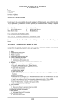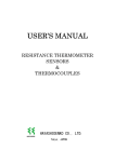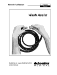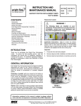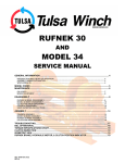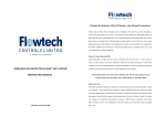
1
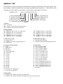
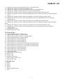
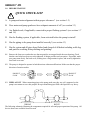
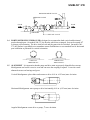
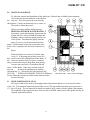
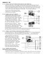
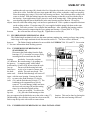
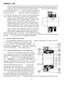
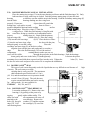
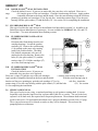
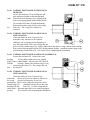
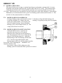
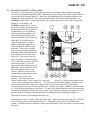
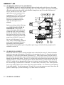
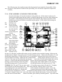
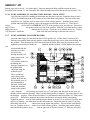
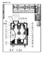
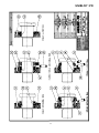
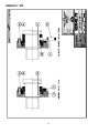
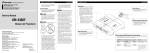
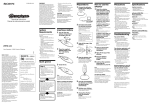
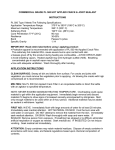
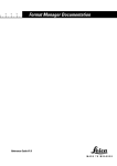
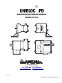
UNIBLOC -PD OPERATION AND SERVICE MANUAL (MODELS 200-575) 1701 Spinks Drive SE Marietta, GA 30067-8925 USA PH: 770-218-8900 - FX: 770-218-8442 [email protected] www.flowtechdiv.com KNFLODER\MANUALS TECHNICAL MANUAL NO. 20001298 UNIBLOC-PD 2 UNIBLOC-PD TABLE OF CONTENTS Pump Identification ..................................................................................................................... 3 Section 1.0 Before Start-Up......................................................................................................... 5 Section 2.0 Shaft Seal Service...................................................................................................... 10 Section 2.1 Single Mechanical................................................................................................. 10 Section 2.2 Flushed Single Mechanical ................................................................................... 12 Section 2.3 Double Mechanical ............................................................................................... 13 Section 2.4 Double O-LIPTM .................................................................................................... 14 Section 2.5 Flushed Double O-LIPTM ...................................................................................... 15 Section 2.6 Single O-ring......................................................................................................... 15 Section 2.7 Double O-ring ....................................................................................................... 17 Section 2.8 Seal Installation-Final Steps ................................................................................. 18 Section 3.0 Gearbox Maintenance and Service ......................................................................... 19 Section 3.1 Gearbox Disassembly ........................................................................................... 19 Section 3.2 Gearbox Assembly ................................................................................................ 20 Section 3.2.1 Assembly With Stainless Steel Rotors............................................................... 20 Section 3.2.2 Assembly With Polymer Rotors......................................................................... 21 Section 3.3 Lubricants and Gearbox Volumes......................................................................... 22 Section 3.4 Torque Requirements and Limits.......................................................................... 23 Section 4.0 Rotor Clearance Tables............................................................................................ 24 Section 5.0 Relief Valve Cover Setting and Maintenance ........................................................ 25 Troubleshooting Table................................................................................................................. 26 Parts Lists ..................................................................................................................................... 28 Warranty....................................................................................................................................... 34 PUMP IDENTIFICATION 3 UNIBLOC-PD Each pump has a unique serial number machined into the gearbox and stamped on the rotor housing. The type of pump is further described by the series number machined into the gearbox, i.e. 5000, 4000 or 3000. A pump may be described by a part number, as shown below, that indicates its features. UNIBLOC-PD 5400-10-10-P20H-60-10T-12-E J. Elastomer type H. Shaft seal type G. Shaft type F. Rotor type A. Series B. Pump model C. Rotor cover type D. Rotor housing type E. Connection type and size A. Series: 5000 - all stainless 4000 - stainless rotor housing, aluminum gearbox 3000 - stainless rotor housing, steel gearbox B. Pump Model: 200 - UNIBLOC 200 (1/2” & 3/4” connections) 250 - UNIBLOC 250 (3/4” connections) 275 - UNIBLOC 275 (1.0” connections) 300 - UNIBLOC 300 (1.0” connections) 350 - UNIBLOC 350 (1.5” connections) 400 - UNIBLOC 400 (1.5” connections) 450 - UNIBLOC 450 (2.0” connections) 500 - UNIBLOC 500 (2.5” connections) 550 - UNIBLOC 550 (3.0” connections) 575 - UNIBLOC 575 (4.0” connections) C. Rotor Cover Type: D. Rotor Housing Type: 10 - standard cover 15 - standard cover with cooling/heating jacket 20 - vented cover 10 - standard sanitary housing 15 - standard housing with cooling/heating jacket E. Connection Type & Size: F. Rotor Type: P - Clamp L - ACME thread K - NPT male D - DIN thread AF - 150# ANSI flange DF - DIN flange 04 - 3/8 inch 05 - 1/2 inch 07 - 3/4 inch 10 - 1.0 inch 15 - 1.5 inch 20 - 2.0 inch 25 - 2.5 inch 30 - 3.0 inch 40 - 4.0 inch 60 - 6.0 inch 80 - 8.0 inch H - horizontal port configuration V - vertical port configuration 20 - Class A, polymer (PET) 21 - Class B, polymer (PET) 50 - Class A, polymer (PEEK) 51 - Class B, polymer (PEEK) 60 - Class C, 316 stainless steel 61 - Class D, 316 stainless steel 62 - Class E, 316 stainless steel 63 - Class F, 316 stainless steel 64 - Class G, 316 stainless steel 70 - Class A, polymer (PTFE) 71 - Class B, polymer (PTFE) 80 - Class C, nongalling stainless steel 81 - Class D, nongalling stainless steel 82 - Class E, nongalling stainless steel 83 - Class F, nongalling stainless steel 84 - Class G, nongalling stainless steel X - customized G. Shaft Type: 10 - standard 316L stainless steel shaft for metallic rotor 11 - standard 316L stainless steel shaft with hardened seal area for metallic rotor 4 UNIBLOC-PD 12 - standard 316L stainless steel shaft with wear sleeve for metallic rotor 15 - standard 316L stainless steel shaft for nonmetallic rotor 16 - standard 316L stainless steel shaft with hardened seal area for nonmetallic rotor 17 - standard 316L stainless steel shaft with wear sleeve for nonmetallic rotor 20 - standard 316L stainless steel drive shaft for metallic rotor and for Charlynn hydraulic motor 21 - standard 316L stainless steel drive shaft with hardened seal area for metallic rotor and for Charlynn hydraulic motor 25 - standard 316L stainless steel drive shaft for nonmetallic rotor and for Charlynn hydraulic motor 26 - standard 316L stainless steel drive shaft with hardened seal area for nonmetallic rotor and for Charlynn hydraulic motor 30 - standard 316L stainless steel drive shaft for metallic rotor and for Danfoss hydraulic motor 31 - standard 316L stainless steel drive shaft with hardened seal area for metallic rotor and for Danfoss hydraulic motor 35 - standard 316L stainless steel drive shaft for nonmetallic rotor and for Danfoss hydraulic motor 36 - standard 316L stainless steel drive shaft with hardened seal area for nonmetallic rotor and for Danfoss hydraulic motor T - top mounted drive shaft B - bottom mounted drive shaft H. Shaft Seal Type: 10 - single mechanical carbon vs. stainless steel 11 - single mechanical carbon vs. tungsten carbide 12 - single mechanical silicone carbide vs. tungsten carbide 13 - single mechanical carbon vs. tungsten carbide 20 - single mechanical #10 with retaining ring 21 - single mechanical #11 with retaining ring 22 - single mechanical #12 with retaining ring 30 - double mechanical #10 primary & #10 secondary with flush housing 31 - double mechanical #11 primary & #10 secondary with flush housing 32 - double mechanical #12 primary & #10 secondary with flush housing 40 - single mechanical #10 with flush housing 41 - single mechanical #11 with flush housing 42 - single mechanical #12 with flush housing 50 - gland packing PTFE 51 - gland packing with lantern ring 60 - single o-ring 61 - double o-ring 70 - double O-LIPTM Seal 71 - flushed double O-LIPTM Seal 72 - triple O-LIPTM Seal J. Elastomer Type: E - EPDM K - Kalrez N - Buna N S - Silicone T - Teflon encapsulated viton V - Viton 5 UNIBLOC-PD 1.0 BEFORE START-UP ! QUICK CHECK LIST A. Is pump and motor alignment within proper tolerances? (see section 1.5) B. Does motor and pump gearboxes have adequate amounts of oil? (see section 3.3) C. Are flushed seals, if applicable, connected to proper flushing systems? (see sections 1.7 and 1.8) D. Has the flushing system, if applicable, been activated before the pump is started? E. Has the piping to the pump been installed correctly? (see section 1.3) F. Has the system and all pipes been flushed and cleaned of all debris including weld slag and particles resulting from polishing and grinding? 1.1 Remove the front cover and make sure that no particles are trapped inside the rotor housing. Check that the rotor bolts have been securely tightened, if design provides such an option. If possible, make sure pump turns freely. Put back cover, making sure o-ring remains in place, and securely tighten the four front cover nuts. 1.2 The pump is designed to operate in both directions without modifications. Make sure that the proper direction of rotation applies. PRODUCT FLOW PRODUCT FLOW 1.3 PIPE LAYOUT When connecting pipes to the pump, make sure they are well supported, as the pump is not meant to serve this purpose. Keep in mind that pipes filled with liquid are very heavy. WRONG RIGHT The following schematic illustrates the components required for safe and proper operation of the pump. All devices shown are available from Flowtech. 6 UNIBLOC-PD PRESSURE RELIEF VALVE PRESSURE GAUGE FLOW FLOW STRAINER SHUT OFF VALVE 1.4 PORT POSITIONING UNIBLOC-PD is designed to accommodate both vertical and horizontal product through-puts. On models 200-275, the bracket, which has an integral, foot can be rotated 900 to change port orientation. The drive shaft oil seal and plug must also be switched. On models 300575, the gearbox is predrilled to accommodate custom installation or to use standard feet for horizontal port orientation or pedestals for vertical orientation. VERTICAL THROUGH-PUT HORIZONTAL THROUGH-PUT 1.5 ALIGNMENT It is imperative that the pump and drive train are properly aligned before start-up. Misalignment can lead to excessive wear and can cause the coupling to rupture. It can also create abnormal stresses on bearings and gears. Vertical Misalignment: place shims under pump or drive; 0.01 in. (0.25 mm) max. deviation Horizontal Misalignment: move pump or drive horizontally; 0.01 in. (0.25 mm) max. deviation Angular Misalignment: rotate drive or pump; 10 max. deviation 7 UNIBLOC-PD 1.6 CLEAN SYSTEM OF ALL DEBRIS BEFORE FINAL STARTUP. Any remaining particles larger than 0.002 in. (0.05 mm) can damage the pump if they enter it. A filtering device installed before the pump inlet is highly recommended to insure safe and proper operation. Since such a device will restrict the flow in to the pump, it is necessary to verify that the net positive suction head (NPSH) available is not reduced below that required by the pump. Flowtech stocks in-line strainers which will prevent hazardous objects from entering the pump and will capture them for easy removal from the system. 1.7 SINGLE AND DOUBLE MECHANICAL SEAL FLUSHING/COOLING Double mechanical shaft seals must be fitted with flushing systems that will cool and lubricate them, otherwise the seals will NOT OPERATE CORRECTLY. Single mechanical shaft seals are provided with flush housings as an option. The flushing system also provides a barrier of protection between the environment and the pumped media. The fluid in this system must be flowing before or at the same time the pump is engaged. It must also be stopped after or at the same time the pump is disengaged. Flushing systems are normally not included with the pump. The following piping arrangements and system components are recommended for satisfactory operation of the seals and to insure containment of the pumped liquid. Connections to the seal housings are 1/8” NPTF. The minimum flow rate for the flushing system is 1 lpm (0.3 gpm) or a rate that will keep the temperature of the seals within 50C (90F) of the pumped media. The pressure of the flushing system is dependent upon the requirements of the pumping application. As a guide, when the flushing system pressure is higher than that of the pumped media, the flushed liquid will enter into the media if the seal fails. Likewise if the pumped media has a higher pressure than the flushing system, the media will enter into the flushing system if the seals fail. This is usually beneficial in cases when the pumped media is extremely hazardous, as it may be safely contained and disposed of properly. 8 UNIBLOC-PD FLUSH INLET SHUT OFF VALVE FLUSH OUTLET FLUSH OUTLET CONTROL VALVE (i.e diaphragm valve) PRESSURE GAUGE CHECK VALVE CONTROL VALVE (i.e diaphragm valve) PRESSURE GAUGE CHECK VALVE HORIZONTAL PUMP PORTS (recommended piping arrangement) SHUT OFF VALVE FLUSH INLET VERTICAL PUMP PORTS (recommended piping arrangement) TYPICAL PIPING ARRANGEMENTS The illustrations below show alternative methods of arranging the flushing system and its components. Although not ideal, they are adequate for less critical pump applications. FLUSH OUTLET CONTROL VALVE (i.e diaphragm valve) FLUSH OUTLET PRESSURE GAUGE CONTROL VALVE (i.e diaphragm valve) PRESSURE GAUGE CHECK VALVE SHUT OFF VALVE CHECK VALVE FLUSH INLET SHUT OFF VALVE FLUSH INLET ALTERNATE PIPING ARRANGEMENTS 9 UNIBLOC-PD 1.8 DOUBLE O-RING SEAL FLUSHING/COOLING Double o-ring shaft seals, like the double mechanical seals, must also be fitted with flushing systems that will cool and lubricate them, otherwise the seals will NOT OPERATE CORRECTLY. The flushing system also provides a barrier of protection between the pumped media and the environment. The fluid in this system must be flowing before or at the same time the pump is engaged. It must also be stopped after or at the same time the pump is disengaged. The flushing system may be arranged the same as the double mechanical seals, shown in Section 1.7. The double o-ring seals may also be lubricated with grease if the pump application justifies doing so. In this case, the seal flush chambers are filled through grease nipples with an approved grease that is suitable for use with the pumped media. The chambers must be filled completely for proper operation. This can be accomplished by over pressurizing the chambers such that grease will be squeezed out of the seals along the shafts and in to the rotor housing. The amount of grease in the seal chambers must be monitored daily and if the pump is used in constant duty applications, should be checked several times every 24 hour period. 1.9 OPERATION WITH PULLEY The drive shaft and gearbox on all UNIBLOC pump models have been designed for use with in-line couplings and motors. When pulley driven systems are to be used, external supports, as illustrated below, must be provided to prevent excessive bearing wear and bending of the drive shaft. 10 UNIBLOC-PD 2.0 SHAFT SEAL SERVICE To aid in the removal and installation of the shaft seals, Flowtech has available plastic mounting sleeves that are the same diameter as the shafts at the seal area. They also protect the seals from the shaft splines. Contact an authorized service center, or Flowtech, to obtain these tools. Before proceeding with the following steps, DISENGAGE POWER TO THE MOTOR. If the pump is connected to piping, depressurize the system and close valves on both the suction and discharge sides to isolate the pump from the rest of the system. Disconnect the piping from the pump. If service is to be performed while the pump is still mounted to the system, disconnect the motor drive coupling or the electrical connection to the Motor. Remove the front cover nuts (16) and the front cover (2). If the pump has polymer rotors (3b) they can be removed by sliding them off the shafts. If the rotors are stainless steel (3a), place a nonmeta object between the rotors to keep them from turning. Unscrew the rotor bolts (14) and then slide the rotors off the shafts. If the rotors will not slide off they can be removed simultaneously with the rotor housing (1). Unless they are being replaced, DO NOT USE PLIERS OR CHANNEL LOCKS TO REMOVE See the following sections for further instructions to remove the rotor housing. THE ROTORS. They will be damaged. 2.1 SINGLE MECHANICAL SEAL This type of shaft seal is used in most applications with products that have a viscosity of less than 1,000 cPs. The maximum rotational speed of this seal is 1500 rpm and the maximum service pressure is 13.5 bar (195 psig). The seal materials available are stainless steel, carbon, silicone carbide, and tungsten. The standard o-rings supplied in these seals are viton or EPDM, either food or FDA grade, but may be replaced with other materials. 11 UNIBLOC-PD 2.1.1a UNIBLOC 200, 250, 275 SINGLE MECHANICAL SEAL REMOVAL Remove the four studs (15) by locking two M6 nuts against each other on the threaded stud end. Remove the rotor housing (1) by pulling on the ports or by tapping gently with a rubber mallet. Do not rock the housing back and forth excessively. The seals may break. Remove the seal nose rings (B) and o-rings (48b) by pulling them out of the housing. Remove the mating rings (A), the o-rings (48a), and the washers (D) by sliding them off the shafts. To avoid damage, handle and store the loose seal nose rings (B) and the mating rings (A) so that their lapped sealing surfaces do not get scratched. 2.1.1b UNIBLOC 200, 250, 275 SINGLE MECHANICAL SEAL INSTALLATION If missing, insert the dowel pins (47) in the shafts and rotor housing. Coat the shafts and rotor housing bores with a product compatible lubricant. Place the o-rings (48a) in the mating rings (A) first, and then the washers (D). Slide the mating rings, slotted side first, on the shafts. Place the spring washers (C) between the pins (47) in the rotor housing. Place the o-rings (48b) in the groove of the mating rings (B). Align the slots of the mating rings with the pins in the rotor housing. Push the mating rings into the rotor housing, o-ring side first. Press several times to make sure they slide easily. Place a product compatible lubricant on the sealing surfaces. Proceed to section 2.8 to complete the installation. 2.1.2a UNIBLOC 300-575 SINGLE MECHANICAL SEAL REMOVAL Loosen the stud nuts (43). Remove the tapping gently with a rubber mallet. Do not rock the housing back and forth excessively. The seals may break. The retainer rings (31), if used, the bolts (32), the mating rings (A), and the mating ring o-rings (33a) will all come off with the housing. Unscrew the bolts (32) to remove the optional retainer rings (31), the mating rings (A), and the mating ring o-rings (33a). Slide the seal nose rings (B) and the seal nose o-rings (33b) off the shafts. To avoid damage, handle and store the loose seal nose rings and the mating rings so that their lapped sealing surfaces do not get scratched. If not being replaced, the drive collars (C) may remain on the shafts, otherwise loosen the set screws (D) and slide them off the shafts. 2.1.2b UNIBLOC 300-575 SINGLE MECHANICAL SEAL INSTALLATION The shafts and the rotor housing bores should be cleaned before installing the seal components. Slide the drive collars (C) on the shafts. Moisten the seal nose o-rings (33b) with water or coat them with a lubricant that is acceptable for use with the product. Slide the seal nose o-rings on the shafts 12 UNIBLOC-PD and then the seal nose rings (B), slotted sides first. Align the slots in the seal nose rings with the pins in the drive collar. Push the seal nose rings against the drive collars so that the o-rings seat properly. Place the mating ring o-rings (33a) in the rotor housing seal bores. Only lubricate these o-rings with water or alcohol. Push the mating rings into the rotor housing so that they seat flat with the step in the housing. Some applications require pins to be used in the mating rings. When placing them in the rotor housing align the pins with the holes in the rotor housing and press them in. Do not use objects that will scratch the mating rings’ seal surface to push them in. Place a product compatible lubricant on the sealing surfaces. If retainer rings (31) were supplied with the pump, bolt them to the rotor housing. Proceed to section 2.8 to complete the installation. After installing the housing push the drive collars toward it compressing the wave springs and leaving a 2-3mm (0.08”-0.12”) gap between the collar and the seal nose rings (B). Tighten the set screws (D). 2.2 FLUSHED SINGLE MECHANICAL SEAL The flushed single mechanical seal uses the same stationary mating ring, rotating seal nose ring, spring, and o-rings as the single mechanical seal discussed in section 2.1. The drive collar is different, however. The flushed single mechanical is not available for UNIBLOC 200, 250, and 275. See section 1.7 for more information about flushing systems. 2.2a FLUSHED SINGLE MECHANICAL SEAL REMOVAL Disconnect the flush tubing from the flush housings (55). Loosen the set screws (D) by inserting an allen wrench into the flush housing port holes. Loosen the stud nuts (43). Remove the rotor housing (1) by pulling on the ports or by tapping gently with a rubber mallet and lay it rotor cavity down so that the seals face up. Do not rock the housing back and forth exces- sively or let it come in contact with the shaft splines. The seals may break. The entire seals with the flush housings will come off intact with the rotor housing. Unscrew the bolts (32) to remove the flush housings (55), the lip seals (56), and the flush housing o-rings (37). The remaining seal components may now be removed. To avoid damage, handle and store the loose seal nose rings (B) and the mating rings (A) so that their lapped sealing surfaces do not get scratched. To remove the lip seals (56), place the flush housings so that they are supported at the bolt holes not at the at the o-ring (37) flush housings, after all other seal parts have been removed, Push or tap the lip seals with a tube to remove them. 2.2b location. This can be done by placing the back into the rotor housing seal bores. FLUSHED SINGLE MECHANICAL SEAL INSTALLATION 13 UNIBLOC-PD Place the mating ring o-rings (33a) in the rotor housing seal bores. Only lubricate these o-rings with water or alcohol. Push the mating rings into the rotor housing so that they seat flat with the step in the housing. Do not use objects that will scratch the mating rings’ seal surface to push them in. Check the drive collars (C) for wear at the lip seal location. If a groove is present, the drive collars may need to be replaced. If the lip seals (56) have been removed, place the flush housings (55) so that the o-ring groove edges face up. Lubricate the lips and the outer diameters of the lip seals. Push the lip seals, spring sides facing up, into the flush housings with a tube that is the same MOUNTING diameter as the lip seals. Place the o-rings (37) into the o-ring SLEEVE grooves. Lubricate the shafts, the outside of the plastic mounting sleeves, and the drive collars at the lip seal location. Slide the flush housings on the drive collars. Slide the flush housings with the drive collars, seal nose o-rings (33b), and the seal nose rings (B), slotted sides first, on the plastic mounting sleeves. Align the slots with the pins in the drive collars and push the seal nose rings so that the o-rings (33b) seat properly. Place a product compatible lubricant on the sealing surfaces. Rotate the flush housings so that its port holes align with at least one set screw. Lubricate the o-rings (37) and mount the seal cartridge assemblies on the rotor housing. Tighten the bolts 32). See section 2.8 to complete the installation. 2.3 DOUBLE MECHANICAL SEAL The flushed double mechanical seal uses the same stationary mating rings (A, F) and o-rings (33a, 33b) as the single mechanical seals discussed in section 2.1.2. The drive collar (D) and seal nose rings (B, E) are different, however. The flushed double mechanical seal is not available for UNIBLOC 200, 250, and 275. See section 1.7 for more information about flushing systems. 2.3a DOUBLE MECHANICAL SEAL REMOVAL Disconnect the flush tubing from the flush housings (36). Loosen the set screws (C) by inserting an allen wrench into the flush housing port holes. Loosen the stud nuts (43). Remove the rotor housing (1) by pulling on the ports or by tapping gently with a rubber mallet and lay it rotor cavity down so that the seals face up. Do not rock the housing back and forth excessively or let it come in contact with the shaft splines. The seals may break. The entire seals with the flush housings will come off intact with the rotor housing. Unscrew the bolts (32) to remove the flush housings (36), the secondary mating ring (F), and the orings (37, 33a). The remaining seal components may now be removed. To avoid damage, handle and store the loose seal nose rings (B, E) and the mating rings (A, F) so that their lapped sealing surfaces do not get scratched. Remove the primary mating rings (A) by pulling it out of the rotor housing seal bores. Remove the secondary mating rings (F) by pushing them out of the flush housings. 14 UNIBLOC-PD 2.3b DOUBLE MECHANICAL SEAL INSTALLATION Place the mating ring o-rings (33a) in the rotor housing seal bores and the flush housings (36). Only lubricate these o-rings with water or alcohol. Push the primary mating rings (A) into the rotor housing so that they seat flat with the step in the housing. Push the secondary mating rings (F) into the flush housings making sure the o-rings seat properly. Do not use objects that will scratch the mating rings’ seal surface to push them in. Place a product compatible lubricant on the sealing surface of the mating rings. Place the o-rings (37) into the o-ring grooves. While the rotor housing is lying flat with MOUNTING the rotor bores facing up, stack the seal components on the SLEEVE primary mating rings (A). Begin with the primary seal nose rings (B), slotted sides up. Place the o-rings (33b) into the seal nose rings (B, E). Place the drive collars (C) into the seal nose rings, align the slots with the pins, and push gently to seat the o-rings. Place the secondary seal nose rings (E) on the drive collars, align the slots with the pins, and push gently to seat the orings. Place the flush housings (36) over the stacked components, rotating them to make sure one set screw will be visible through the port holes in the flush housings. Push the housings down gently and screw in the bolts (32) hand tight only. Lubricate the plastic mounting sleeves and slide them, tapered end first, into the seals. Tighten the bolts (32). Leave the sleeves in the seals and proceed to section 2.8 to complete the installation. 2.4 DOUBLE O-LIPTM SEAL This type of seal is most frequently used with liquids that are very difficult to seal because of viscosity. The seal comes as a single cartridge that is easily serviced. The maximum shaft rotational speed for this seal is 1.5 m/s (4.9 ft/s) and the maximum service pressure should not exceed 10 bar (150 psig). The seal does not require external lubrication and can be run dry for short periods. It is not available for UNIBLOC 200, 250, and 275. DOUBLE O-LIPTM SEAL REMOVAL Loosen the stud nuts (43). Remove the rotor housing (1) by pulling on the ports or by tapping gently with a rubber mallet. The entire seal with all components will come off attached to the rotor housing. Remove the bolts (50), the split washers (51), and the retainer rings (52). Pull the cartridges (53) out of the rotor housing bores. 2.4a 15 high UNIBLOC-PD DOUBLE O-LIPTM SEAL INSTALLATION Check the shafts for wear. If grooves are noticeable, they may have to be replaced. Place new orings (49) into the groove of the seal cartridges. Clean the rotor housing seal bores. Apply product compatible lubricant to the bores and the shafts. Place the rotor housing so that the seal bores are pointing up, push the seal cartridges (53) in, lip side first. Attach the retainer rings (52) to the rotor housing with the split washers (51) and the bolts (52). See section 2.8 for completing the installation. 2.4b 2.5 FLUSHED DOUBLE O-LIPTM SEAL This type of seal has the same features as the unflushed seal described in section 2.4. Its ability to be flushed provides an added barrier of protection. It is not available for UNIBLOC 200, 250, and 275. See section 1.7 for more information about flushing systems. 2.5a FLUSHED DOUBLE O-LIPTM SEAL REMOVAL Disconnect the flush tubing from the seal cartridge housings. Loosen the gearbox stud nuts (43). Remove the rotor housing (1) by pulling on the ports or by tapping gently with a rubber mallet. The entire seal with all components will come off attached to the rotor housing. Remove the bolts (50), the split washers (51), and the retainer rings (52). Pull the cartridges (57) out of the rotor housing bores. FLUSHED DOUBLE O-LIPTM SEAL INSTALLATION Check the shafts for wear. If grooves are noticeable, they may have to be replaced. Place new o-rings (58) into the step of the seal cartridges. Clean the rotor housing seal bores. Apply product compatible lubricant to the bores and the shafts. With the rotor housing lying so that the seal bores are pointing up, push the seal cartridges (57) in, lip side first. Attach the retainer rings (52) to the rotor housing with the split washers (51) and the bolts (52). See section 2.8 for completing the installation. 2.5b 2.6 SINGLE O-RING SEAL This type of seal uses one o-ring, or optional quad ring, to seal against a rotating shaft. It is most frequently used when the liquid viscosity is greater than 2,000 cPs or is sticky. The seal is the least expensive of all shaft seals, but requires more frequent replacement. The maximum shaft rotational speed for this seal is 350 rpm and the maximum service pressure should not exceed 8 bar (115 psig). The o-ring seal must never be allowed to run dry as they will be damaged. This seal uses the pumped product as a lubricant. 16 UNIBLOC-PD 2.6.1a UNIBLOC 200-275 SINGLE O-RING SEAL REMOVAL Loosen the stud nuts (15) by locking two M6 nuts against each other on the threaded stud ends. Remove the rotor housing (1) by pulling on the ports or by tapping gently with a rubber mallet. All seal parts will come off with the housing. Remove the retainer rings (50) by unscrewing the bolts (52). The o-rings (51) can now be removed. 2.6.1b UNIBLOC 200-275 SINGLE O-RING SEAL INSTALLATION Check the shafts for wear. If grooves are noticeable, they may have to be replaced. Otherwise, the o-ring may not seal properly or may fail prematurely. Place new o-rings into the grooves of the retainer rings (50). Apply a lubricant on the shafts, o-rings, and the rotor housing bores with a lubricant approved for use with the pumped product. Attach the retainer rings to the rotor housing with the bolts (52). See section 2.8 for completing the installation. 2.6.2a UNIBLOC 300-575 SINGLE O-RING SEAL REMOVAL Loosen the stud nuts (43). Remove the rotor housing (1) by pulling on the ports or by tapping gently with a rubber mallet. All seal parts will come off with the housing. Remove the retainer rings (39) by unscrewing the bolts (32). The o-rings (40) can now be removed. 2.6.2b UNIBLOC 300-575 SINGLE O-RING SEAL INSTALLATION Check the shafts for wear. If grooves are noticeable, they may have to be replaced. Otherwise, the o-ring may not seal properly or may fail prematurely. Place a new o-ring into the groove of the retainer ring (39). Attach the retainer ring to the rotor housing with the bolts (32). Coat the o-ring and the shafts with a lubricant approved for use with the pumped product. See section 2.8 for completing the installation. 17 UNIBLOC-PD 2.7 DOUBLE O-RING SEAL This type of seal uses two o-rings, or optional quad rings, to seal against a rotating shaft. It is most frequently used when the liquid viscosity is greater than 2,000 cPs or is sticky. The maximum shaft rotational speed for this seal is 350 rpm and the maximum service pressure should not exceed 8 bar (115 psig). This seal must never be allowed to run dry because the o-rings will be damaged. It must also be lubricated by an external method such as grease or a flushing system as discussed in section 1.8. This seal also uses the pumped product as a lubricant. 2.7a DOUBLE O-RING SEAL REMOVAL If using a flushing system as discussed in section 1.7, disconnect it from the flush housings (41). Loosen the stud nuts (43). Remove the rotor housing (1) by pulling on the ports or by tapping gently with a rubber mallet. All seal parts will come off with the housing. Remove the flush housings (41) by unscrewing the bolts (32). The o-rings (40) can now be removed. 2.7b DOUBLE O-RING SEAL INSTALLATION Check the shafts for wear. If grooves are noticeable, they may have to be replaced. Otherwise, the o-rings may not seal properly or may fail prematurely. Place new o-rings into the grooves of the flush housings (41). Attach the flush housings to the rotor housing with the bolts (32). Coat the o-rings and the shafts with a lubricant approved for use with the pumped product. See section 2.8 for completing the installation. It is imperative that the cavity between the o-rings is filled with grease or the flushing system is reconnected before operation is resumed. 18 UNIBLOC-PD 2.8 SEAL INSTALLATION - FINAL STEPS See section 3.4 for torque limits. If not part of the shaft seal assembly, slide the plastic mounting sleeves over the splined ends of the shafts. Slide on the rotor housing (1) tap it with a rubber mallet to seat it properly on the dowel pins (20). Make sure the alignment mark on the rotor housing lines up with the one on the gearbox (6). The rotor housing must make firm contact with the gearbox. On UNIBLOC models 300-575, fasten the hex nuts (43) with the split washer (44) on the stud ends and tighten in a cross pattern. On UNIBLOC models 200-275, insert the one piece studs (15) through rotor housing and thread into the gearbox. Tighten them in a cross pattern by locking two M6 nuts against each other on the protruding stud ends. Remove the plastic sleeves from the shaft ends. If the shaft seals are either flushed single or flushed double mechanical, tighten the set screws through the flush housings’ port holes. If the rotors are made from a polymer (nonmetal) material, slide them on the shafts and turn the drive shaft to make sure the rotors turn freely. They do not require Orings (26) and (27) or the rotor bolts (14). If the rotors are metal, slide the rotor shaft o-rings (27) over the splined shaft ends and on the step, if applicable. One rotor and one shaft have been marked with the same symbol. Slide the rotors over the corresponding shafts and push them making sure the o-rings seat properly. The rotors must make contact with the shafts. Place o-rings (26) on the rotor bolts (14). Lubricate them and the rotor bores. Place a nonmetal object between the rotors to keep them from turning. Thread the rotor bolts in to the shaft ends. Turn the drive shaft to make sure the rotors turn freely. Measure the clearances between the rotor housing and the rotors. Compare these values with those listed in section 4.0. If the measured clearances at positions 1-7, 8, and 10 are smaller than those listed, the rotors must be ground and polished to achieve the correct values. If the measured clearances at positions 9 and 11 are not within the tolerances listed the shafts must be adjusted by disassembling the gearbox, as instructed in section 3.0, and changing the shims (11). Place the front cover (2) and the o-ring (28) on the studs. Tighten the front cover nuts (16). Check the oil level in the gearbox as described in section 3.3. The pump is now ready to be installed in the system. If flushed seals were installed, reconnect the flush tubing. Refer to section 1.0 before starting the pump. 19 UNIBLOC-PD 3.0 GEARBOX MAINTENANCE AND SERVICE The UNIBLOC gearbox is supplied permanently lubricated with nitrile seals. However, for certain applications and at the user’s request, drain plugs and a vent will be supplied. The oil level should be checked at regular intervals and the seals should be changed once per year or after 2000 hours of service, whichever occurs first. When applications exceed constant service temperatures of 1800C (3560F) a vent and high temperature lubricant must be used. For such cases, contact Flowtech or an authorized service center for an adequate service schedule. Before proceeding with the following steps, DISENGAGE POWER TO THE MOTOR. If the pump is connected to piping, depressurize the system and close valves on both the suction and discharge sides to isolate the pump from the rest of the system. Disconnect the piping and remove the pump from the system. Removal of the wet end of the pump (i.e. the cover, rotors, rotor housing, and shaft seals) must be completed first before disassembly of the pump gearbox. The method of removing these parts is dependent upon the type of shaft seals the pump has and is outlined in section 2.0. 3.1 GEARBOX DISASSEMBLY Remove the front cover, rotors, housing and shaft seals as described in section 2. Drain oil from the gearbox by removing the drain plug, if available, or by removing the cover (7). Open the tab on the tabwashers (12) and remove them and the slotted nuts (13). With a rubber mallet, strike the ends of the shafts where the tabwashers were located to loosen the gears (8) and remove them. Be sure not to damage the threads on the shafts. The keys (21) will now be exposed and can be removed with a flat tipped screwdriver. Continue striking the shafts with the rubber mallet to push the shafts and the oil seals (23), which will get damaged and will have to be replaced, out of the gearbox. Each shaft will have one bearing (9) located next to a shoulder. To remove them, if necessary, do so with a hydraulic press or tap with a punch or sleeve on the edge closest to the shoulder. Use caution to prevent damage to the shaft shoulder. Tap the bearing cups , (9) and (10), in a circular pattern to remove them from the gearbox. Behind cup (9) are the shim rings (11) which can now be removed. 3.2 GEARBOX ASSEMBLY 20 UNIBLOC-PD The following steps for assembly assumes that the pump has been completely disassembled. Make sure all parts are clean and free of debris before proceeding. New oil seals are required to complete the assembly. 3.2.1a PUMP ASSEMBLY (STAINLESS STEEL ROTORS) Insert the shim rings (11) into the front bores of the gearbox (6). Oil the front (9) and rear (10) bearing cones and tap them into the gearbox so that the tapered edge can be seen when looking into the gearbox. If the bearings have been removed from the shafts, they must be pressed on with a hydraulic press before the shafts are installed into the gearbox. Oil the shafts at the bearing seat location and slide the bearings on so that the text on the bearing shoulder will make contact with the shaft shoulder. Use extreme caution to not damage the bearing components or the splined shaft end when using the hydraulic press. Place a nonmetal object between the splined shaft end and the hydraulic press to prevent damage to the shaft. Insert both shafts and stand the pump on the splined ends. Slide the rear bearings on, tap the keys (21) into place, and then slide on the gears (8), shoulder side towards the bearings. Make sure the timing marks are aligned. Tap on the gears to seat the bearings properly. Slide on the tabwashers (12) and thread on the slotted nuts (13). Slide on the rotors (3a) and place a nonmetal object between the rotors to keep the shafts from turning. Tighten the nuts so that the shaft rotating torques shown in section 3.4 are achieved. The torque can be measured by inserting the rotor bolts (14) in the splined shaft ends with the rotors on. Do not set the tabs on the tabwashers. Remove the rotor bolts and rotors. Push the rotor housing (1) onto the dowels (20) in the gearbox and tap gently with a rubber mallet to seat it properly. Insert the housing studs (15) and secure them with the split washers (44) and hex nuts (43). The UNIBLOC 200, 250, and 275 has one piece studs (15) and does not use items (43) and (44). To tighten these studs lock two M6 nuts against each other on the stud end. Slide the rotors (3a) on to the corresponding shaft. One rotor and one shaft will be marked with identical symbols. Secure the rotors with the rotor bolts (14). Measure the clearances between the rotors and the housing. If the measured values at positions 8-11 do not correspond with those listed in section 5, then the shim ring(s) (11) must be changed. Remove the rotor bolts, rotors, studs, and then the housing. Unscrew the slotted nuts and remove the tabwashers. Remove the shafts, gears, and keys from the gearbox. Tap out the front 21 UNIBLOC-PD bearing cups only to reveal the shim ring(s). Insert an appropriate shim, and then repeat the steps described in this section. If the clearances fall within the ranges specified, then proceed to section 3.2.1b. 3.2.1b PUMP ASSEMBLY (STAINLESS STEEL ROTORS) - FINAL STEPS Lock the nuts in place by bending the tabwasher into the slots in the nut. Install the front oil seals (23) by first lubricating with oil all contact areas on the shafts and gearbox. The text on the seals should face out. Push the seals on with a sleeve flush with the gearbox. Stand the pump on the splined ends and fill the gearbox cavity with an approved oil listed in section 3.3. Place the oil seal(s) (24; 24 & 45 for UNIBLOC 200-275) in the gearbox cover, text side out. Place the oring (25) into the groove on the rear side of the gearbox. Slide the cover onto the drive shaft taking care not to damage the oil seal lips. Secure the cover with the bolts (18). Tap key (22) into place. Install the shaft seals and rotor housing as described in section 2. 3.2.2 PUMP ASSEMBLY (POLYMER ROTORS) Insert the shim rings (11) into the front bores of the gearbox (6). Oil the front (9) and rear (10) bearing cones and tap them into the gearbox so that the tapered edge can be seen when looking into the gearbox. If the bearings have been removed from the shafts, they must be pressed on with a hydraulic press before the shafts are installed into the gearbox. Oil the shafts at the bearing seat location and slide the bearings on so that the text on the bearing shoulder will make contact with the shaft shoulder. Use extreme caution to not damage the bearing components or the splined shaft end when using the hydraulic press. Place a nonmetal object between the splined shaft end and the hydraulic press to prevent damage to the shaft. Insert both shafts and stand the pump on the splined ends. Slide the rear bearings on, tap the keys (21) into place, and then slide on the gears (8), shoulder side towards the bearings. Make sure the timing marks are aligned. Tap on the gears to seat the bearings properly. Slide on the tabwashers (12) and thread on the slotted nuts (13). Slide on the rotors (3b) and place a nonmetal object between the rotors to keep the shafts from turning. Tighten the nuts so that the shaft rotating torques shown in section 3.4 are achieved. Lock the nuts in place by bending the tabwasher into the slots in the nut. Install the front oil seals (23) by first lubricating with oil all contact areas on the shafts and gearbox. The text on the seals should face out. Push the seals on with a sleeve flush with the gearbox. Stand the pump on the splined ends and fill the gearbox cavity with an approved oil listed in section 3.3. Place the oil seal(s) 22 UNIBLOC-PD (24; 24 & 45 for UNIBLOC 200-275) into the groove on the rear side of the not to damage the oil seal lips. Secure the Install the shaft seals and rotor housing as in the gearbox cover, text side out. Place the o-ring (25) gearbox. Slide the cover onto the drive shaft taking care cover with the bolts (18). Tap key (22) into place. described in section 2. 3.3 LUBRICANTS AND GEARBOX VOLUMES The UNIBLOC pumps come supplied with a synthetic oil, MOBIL 1 15W-50, applicable for service temperatures in the range of -230C (-100F) to 2210C (4300F). The following is a list of other synthetic lubricants that may be used. MANUFACTURER LUBRICANT NAME TEMP. RANGE, 0C (0F) Mobil SHC 627 SHC 634 Spartan EP 100 Spartan EP 150 Spirax S 75W90 S140 -23...121 (-10...250) 121...152 (250...305) -23...121 (-10...250) 121...152 (250...305) -23...152 (-10...305) -26...288 (-15...550) Exxon Shell Sentinel the UNIBLOC MODEL OIL CAPACITY, ml (oz.) 200, 250, 275 300, 350 400,450 500, 550, 575 50 (1.7) 150 (5.1) 350 (11.8) 1700 (57.5) When checking the oil level in permanently lubricated gearboxes, the pump must be removed from the system as described in section 3.0. After removing it, stand the pump on the front cover nuts so that drive shaft points up. Remove the gearbox cover bolts and rotate the cover without sliding it off the drive shaft. Oil should be even with the top of the gears. If not, one of the oils specified above must be added. Replace the cover making sure the o-ring remains in its groove. Tighten the cover bolts. The pump is now ready to be installed in the system. Refer to section 1.0 before starting the pump. When checking the oil level in gearboxes that are not permanently lubricated, the pump must first be stopped. Remove the oil level check plug. If oil does not come out of this hole, it must be added through the vent hole until it starts to do so. Reattach the vent and oil plug and resume operation. 23 UNIBLOC-PD 3.4 TORQUE REQUIREMENTS AND LIMITS UNIBLOC MODEL ROTOR HOUSING STUDS (15), N-m (ft-lbs.) ROTOR BOLTS (14), N-m (ft-lbs.) FRONT COVER NUTS (16) , N-m (ft-lbs.) 200, 250, 275 300, 350 400,450 500, 550, 575 8 (6) 8 (6) 20 (15) 40 (30) 20 (15) 20 (15) 35 (26) 140 (103) 10 (7) 15 (11) 30 (22) 50 (37) UNIBLOC MODEL GEARBOX COVER BOLTS, N-m (ft-lbs.) ROTATING SHAFT, N-m (ft-lbs.) 200, 250, 275 300, 350 400,450 500, 550, 575 20 (15) 15 (11) 15 (11) 40 (30) 2 (1.5) 4 (3) 6 (4.5) 10 (7.5) 24 UNIBLOC-PD 4.0 ROTOR CLEARANCES The following tables list the clearances between the rotor housing and the rotors. The rotors are stamped with the rotor class letter underneath the rotor bolt on the spline ends of the rotor. CLEARANCES FOR CLASS D STAINLESS STEEL ROTORS, x0.01 mm (x0.001in.) UNIBLOC POSITION MODEL 1-6 7 8 & 10 9 &11 10-12 6-8 15-17 4-6 200 CLEARANCES FOR CLASS C STAINLESS STEEL ROTORS, x0.01 mm (x0.001in.) UNIBLOC POSITION MODEL 1-6 7 8 & 10 9 &11 10-12 6-8 12-14 4-6 200 (3.9-4.7) (2.4-3.1) (5.9-6.7) (1.6-2.4) 250 12-14 (4.7-5.5) 6-8 (2.4-3.1) 18-20 (7.1-7.9) 4-6 (1.6-2.4) 4-6 (1.6-2.4) 275 14-16 (5.5-6.3) 6-8 (2.4-3.1) 22-24 (8.7-9.4) 4-6 (1.6-2.4) 12-14 (3.9-5.5) 6-8 (2.4-3.1) 300 15-17 (5.9-6.7) 12-14 (4.7-5.5) 14-16 (5.5-6.3) 6-8 (2.4-3.1) 12-14 (4.7-5.5) 12-14 (3.9-5.5) 6-8 (2.4-3.1) 350 17-19 (6.7-7.5) 16-18 (6.3-7.1) 14-16 (5.5-6.3) 6-8 (2.4-3.1) 18-20 (7.1-7.8) 16-18 (6.3-7.1) 12-14 (4.7-5.5) 7-9 (2.8-3.5) 400 20-22 (7.9-8.7) 20-22 (7.9-8.7) 16-18 (6.3-7.1) 7-9 (2.8-3.5) 450 20-22 (7.9-8.7) 16-18 (6.3-7.1) 14-16 (5.5-6.3) 7-9 (2.8-3.5) 450 22-24 (8.7-9.4) 20-22 (7.9-8.7) 16-18 (6.3-7.1) 7-9 (2.8-3.5) 500 22-24 (8.7-9.4) 22-24 (8.7-9.4) 18-20 (7.1-7.9) 10-12 (3.9-4.7) 500 26-28 (10.2-11.0) 31-33 (12.2-13.0) 24-26 (9.4-10.2) 10-12 (3.9-4.7) 550 26-28 (10.2-11.0) 22-24 (8.7-9.4) 18-20 (7.1-7.9) 10-12 (3.9-4.7) 550 30-32 (11.8-12.6) 31-33 (12.2-13.0) 24-26 (9.4-10.2) 10-12 (3.9-4.7) 575 24-26 (9.4-10.2) 22-24 (8.7-9.4) 18-20 (7.1-7.9) 10-12 (3.9-4.7) 575 30-32 (11.8-12.6) 31-33 (12.2-13.0) 24-26 (9.4-10.2) 10-12 (3.9-4.7) (3.9-4.7) (2.4-3.1) (4.7-5.5) (1.6-2.4) 250 12-14 (4.7-5.5) 6-8 (2.4-3.1) 14-16 (5.5-6.3) 4-6 (1.6-2.4) 275 12-14 (4.7-5.5) 6-8 (2.4-3.1) 16-18 (6.3-7.1) 300 12-14 (3.9-5.5) 10-12 (3.9-4.7) 350 16-18 (6.3-7.1) 400 CLEARANCES FOR CLASS E STAINLESS STEEL ROTORS, x0.01 mm (x0.001in.) UNIBLOC POSITION MODEL 1-6 7 8 & 10 9 &11 18-20 20-22 18-20 6-8 300 350 (7.1-7.9) (7.9-8.7) (7.1-7.9) (2.4-3.1) 20-22 (7.9-8.7) 20-22 (7.9-8.7) 18-20 (7.1-7.9) 6-8 (2.4-3.1) 400 28-30 28-30 (11.0-11.8) (11.0-11.8) 23-25 (9.0-9.8) 7-9 (2.8-3.5) 450 25-27 (9.8-10.6) 28-30 (11.0-11.8) 20-22 (7.9-8.7) 7-9 (2.8-3.5) 500 32-34 38-40 (12.6-13.4) (15.0-15.7) 22-24 (8.7-9.4) 17-19 (6.7-7.5) 550 38-40 39-41 (14.9-15.7) (15.3-16.1) 22-24 (8.7-9.4) 17-19 (6.7-7.5) 575 36-38 39-41 (14.2-15.0) (15.3-16.1) 22-24 (8.7-9.4) 17-19 (6.7-7.5) 25 UNIBLOC-PD 5.0 RELIEF VALVE COVER SETTING AND MAINTENANCE UNIBLOC pumps may be supplied with a relief valve cover, shown at right, that will minimize or eliminate problems associated with overpressurizing the pump. Although a complete external relief system is recommended, the type illustrated in this section is useful when such systems are not practical. This type, however, functions only in one direction and must be oriented such that the high pressure, or discharge, side of the pump is always at the inlet of the relief valve. The pressure is set in conjunction with a pressure gauge installed on the discharge side of the pump. By compressing or decompressing the spring inside the valve, the pressure at which the valve will open can be adjusted. This must be done while the pump is operating at the desired flow rate. Extreme caution should be used to prevent damage to the pump or other equipment that is pressure sensitive. If the pump is used to handle hot liquids, do not touch the pump or the valve without protection. Unscrew the housing (10) to reveal the adjusting mechanism. Release the lock ring (15) and turn it and the adjusting sleeve (16) clockwise until they bottom out. Turn the sleeve counterclockwise until the pressure gauge begins to drop. Lock this position with the lock ring (15). Keep in mind that this pressure must be approximately 0.3- 0.7 bar (5-10 psig) lower than the desired relief pressure, since the pump will continue to build pressure even though the valve may be open. Return the housing (10) and tighten. To service the valve seals the pump must not be operating, the system must be depressurized, and the pump isolated from the remainder of the system. Remove the housing (10) and mark the location of the lock ring (15). Unscrew the adjusting sleeve (16) and remove it. Remove the clamp (13) and separate the valve body and the top containing the spring. Slide the piston, (18) and (17), out and place its stem in a padded vise. Unscrew the tip (17). O-rings (1), (2), and (3) may now be replaced. Screw on the tip (17), roll o-ring (1) into the groove and tighten. Lubricate o-ring (3) and slide in the piston. Place the top with the piston in the valve body (14) and secure with the clamp (13). Turn the lock ring (15) so that it returns to the mark and thread on the adjusting sleeve (16) tight against it. Replace the housing (10) and tighten. The pump may now be returned to service. PROBLEM POSSIBLE CAUSE 26 SOLUTION UNIBLOC-PD A. No flow, but pump turns. Pump does not prime. 1. Motor turning in wrong direction 2. Air pocket in pipe or pump. 3. NPSHA too low. B. Capacity too low, but pump turns. 4. Pump runs too slow. 5. Viscosity too high. 6. Obstruction in discharge piping, valve closed. 1. NPSHA too low. 2. Pump runs too slow. 3. Increased slip in pump. 4. Discharge pressure higher than expected. 4. Front cover not tight. C. Pump is noisy, cavitating. 1.Collapsed suction hose. 2. Liquid temperature too high. 3. Speed too high. 4. Viscosity higher than expected. 5. NPSHA too low. 6. Suction side valve closed. D. Rotors gall, pump seizes 1. Liquid temperature too high. 2. Rotor clearances incorrect. 3. Loose rotor bolts/housing studs. 4. Bearings worn. 5. Gears worn. 6. Foreign particles in pump. 7. Particles in product too large. 8. Discharge pressure too high. 27 1. Reverse motor. 2. Fill pipe and pump with liquid. Check pipe fittings for leaks. 3. Increase suction pipe diameter or shorten suction pipe length. Decrease pump speed. Raise feed tank or supply liquid level. 4. Increase speed. 5. Lower viscosity if possible. 6. Remove obstruction, open valve. 1. See A-3 2. Increase speed. 3. Check rotor clearances; replace worn parts if necessary. 4. Check discharge piping for closed valves or obstructions. Increase pump speed BUT DO NOT EXCEED PRESSURE LIMITS OF PUMP. Increase discharge pipe size. Increase pump size. 4. Tighten cover nuts to torques specified in section 3.4. 1. Use reinforced hose or rigid piping. 2. Reduce speed,increase NPSHA. 3. Decrease speed. 4. Decrease speed, increase pump size. 5. See A-3. 6. Open valve, check suction side piping for obstructions. 1. Lower temperature or increase rotor clearances. 2. Adjust to factory recommended clearances. 3. Tighten or replace if necessary. 4. Replace bearings. 5. Replace gears. 6. Install suction side filter. 7. Increase rotor clearances. Use plastic rotors. Increase pump size. 8. See B-4. UNIBLOC-PD PROBLEM POSSIBLE CAUSE SOLUTION E. Pump is noisy. 1. Cavitation. 2. Liquid contains air. 1. See C. 2. Check pump shaft seals for leaks. Check suction side pipe fittings for leaks. Increase NPSHA. 3. Check suction and discharge piping for closed valves or obstructions. Increase pump size. 1. Increase motor size. 2. Lower pump speed. Lower pressure. Check suction and discharge piping for closed valves or obstructions. 3. Decrease pump speed. Increase pipe size or shorten discharge pipe length. 4. Correct alignment. 1. Reset drive collars. 3. Discharge pressure too high. F. Motor overheating 1. Motor size too small. 2. Discharge pressure too high. 3. Viscosity higher than expected. G. Shaft seals leak. 4. Motor & pump misalignment. 1. Loose drive collar on single mech. seals. 2. Worn parts. 3. Seals have been operated without product in pump or without flushing liquid. 4. Seal incompatible with liquid. 28 2. Replace seals and/or o-rings. 3. Operate pump only when liquids can come in contact with seals. Replace worn seal parts. 4. Contact factory for proper seal selection, operation, and replace if necessary. UNIBLOC-PD 29 UNIBLOC-PD 30 UNIBLOC-PD 31 UNIBLOC-PD 32 UNIBLOC-PD 33 UNIBLOC-PD 34 UNIBLOC-PD WARRANTY Teknoflow Inc.\Flowtech Div. warrants every part of our product against poor workmanship and defective materials for a period of one (1) year from the date of shipment. If during this period the item does not conform to its performance parameters as a result of poor workmanship and/or defective materials, return the faulty item, shipping prepaid and fully insured, to an authorized Flowtech service facility. If, upon inspection of the item in question, poor workmanship or defective materials are revealed, Flowtech will repair or replace it, at Flowtech’s option, and will return it by shipping it F.O.B. the service facility. This warranty is void if the item has not been used as recommended or instructed, has been altered or used with unauthorized accessories, has been subject to misuse, abuse or accident, or has been damaged due to causes not related to poor workmanship or defective materials. All parts or components not manufactured by Flowtech are warranted only to the extent of the warranty of the respective manufacturers. ALL IMPLIED WARRANTIES, INCLUDING THE IMPLIED WARRANTIES OF MERCHANTBILITY AND FITNESS FOR A PARTICULAR PURPOSE, ARE HEREBY EXPRESSLY EXCLUDED. IN NO EVENT SHALL FLOWTECH OR ITS AFFILIATES BE LIABLE TO ANYONE FOR SPECIAL, COLLATERAL, INCIDENTAL, OR CONSEQUENTIAL DAMAGES, WHETHER ARISING IN CONTRACT OR IN TORT. FLOWTECH RESERVES THE RIGHT TO MAKE TECHNICAL CHANGES WITHOUT NOTICE. 35