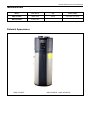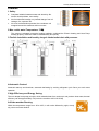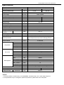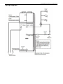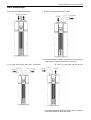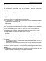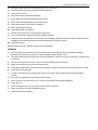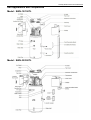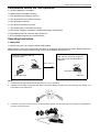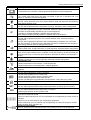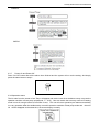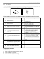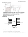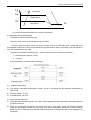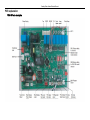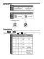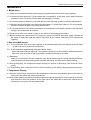
1
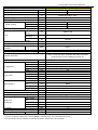
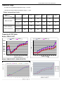
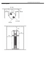
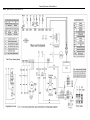
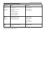
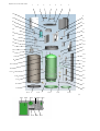
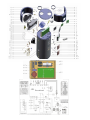
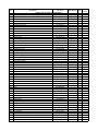
SERVICE MANUAL
HEAT PUMP WATER HEATER
SWH-15/190TL
SWH-35/300TL,SWH-35/300TSL
Sanitary Water Heater Technical Manual
Sanitary Water Heater
Technical Manual
Applicable Model:
SWH-15/190TL
SWH-35/300TL
SWH-35/300TSL
Sinclair reserves the right to discontinue, or change at any time, specifications or designs without notices
and without incurring obligations.
Sanitary Water Heater Technical Manual
Measurements
Model
Dimension
(mm: D x H)
Net weight / Gross weight
(kg)
Power Supply
SWH-15/190TL
568×1640
96/110
220~240V-1ph-50Hz
SWH-35/300TL,
SWH-35/300TSL
650×1,920
123/150
220~240V-1ph-50Hz
External Appearance
SWH-15/190TL
SWH-35/300TL, SWH-35/300TSL
Sanitary Water Heater Technical Manual
Features
1 Safety
a.
Complete isolation between water and electricity. No
electric shock problem, more safety.
b.
No fuel tubes and storage, no potential danger from oil
leakage, fire, explosion etc.
c.
No cross contamination potential, the condenser coil
wrapped around the stainless steel inner tank
2 Max. outlet water Temperature: 70
.
The system is adopted innovative heating methods: combined the Electric heating and Heat Pump
heating properly, made the water be heated stably and quickly.
3 Flexible installation achieved by long air intake/outlet duct with pressure
4 Automatic Control:
Automatic start-up and shutdown, automatic defrosting by revising refrigerant cycle. Save you much extra
operation.
5 High Efficiency and Energy Saving.
The unit adopts heat pump principle, which absorbs heat from outdoor air and produce heat water, thermal
efficiency can be approximately 3.6 (under the condition A15/12 W15/45)
6 All-the-weather Running.
Within the temperature range from -30 to 43
sky, rain even snow whether.
, it will not be affected by night, cloudy
Sanitary Water Heater Technical Manual
Specifications
Model
SWH-15/190T
Running mode
Economy
Running ambient temp.
E-heater
-7 43
Output water Temp.
-30
Default 55 ,38
Power supply
Ph-V-Hz
Storage size
Water heating Capacity
Cop
Max. current
L
kW
kW/kW
A
1-220
240-50
1.50
3.60
6.5
3.00
1.00
13.0
-30
43
Dimension (D×H)
Packing (W×H×D)
Net/gross weight
Noise level
Refrigerant type/Charged volume
Refrigerant design
pressure
mm
mm
kg
dB(A)
kg
568×1640
700×1740×720
96/110
38
R134a/0.95
MPa
3.0/ 1.2
Tank design pressure
MPa
0.15 1.0
System protection
Air flow volume
Compressor
Fan motor
Water pipeline
m³/h
Model
Type
Brand
Capacity
Input
Model
Brand
Input
Speed
Water inlet pipe
Water outlet
pipe
Drainage pipe
PT valve joint
Max. pressure
Design pressure
Btu/h
kW
w
r/min
mm
20'/40'/40H
thermal expansion valve
TCO1, TCO2, PT valve, automatic defrosting,
over-load protector temp. electric leakage protector
etc.
414/355/312
PJ125G1C-4DZDE
Rotary
GMCC
4740
0.515
YDK12-6A
welling
28
900/815/680
DN20
mm
DN20
mm
mm
MPa
DN20
DN20
1.2
MPa
0.15 1.0
kW
m³/h
Pcs
Dividing wall type heat exchanger
3.0
0.045
0.075
24/51/51
Heat exchanger
E-heater
Hot water yield
Loading Quantity
70
190
Ambient temp.
Throttling type
43
Remark:
1. The test conditions: outdoor temp. 15/12
(DB/WB), inlet water temp. 15
, outlet water temp.45
2. The specification may be changed for product improvement, please refer to the nameplate.
.
Sanitary Water Heater Technical Manual
Model
Running mode
SWH-35/300TL, SWH-35/300TSL
Economy
E-heater
Running ambient temp.
-7 43
Outlet water Temp.
Default 55 ,38
Power supply
Storage size
Water heating
-30
Ph-V-Hz
Capacity
Cop
Max. current
L
kW
kW/kW
A
3.00
3.60
6.5
Unit
Noise level
Refrigerant type/quantity
Refrigerant design
pressure
Tank design pressure
Throttling type
-30
Dimension
(D×H)
Packing
(W×H×D)
Net/gross
weight
mm
Water pipeline
Max. pressure
Design pressure
Heat exchanger
Solar heat
exchanger
E-heater
Hot water yield
Loading Quantity
650×1,920
750×2,150×780
kg
123/150
dB(A)
kg
48
R134a/1.2
MPa
3.0/1.2
MPa
1
Electric expansion valve
TCO1, TCO2, PT valve, automatic defrosting, over-load
protector temp. electric leakage protector etc.
Air flow
Fan motor
3.00
1.00
13.0
43
mm
System protection
Compressor
60
1-220 240-50
300
Ambient temp.
43
m³/h
Model
Type
Brand
Capacity
Input
Model
Brand
Input
Speed
Water inlet pipe
Water outlet
pipe
Drainage pipe
PT valve joint
Water inlet pipe
Water outlet
pipe
Heat exchanger
Dim.×Length
Max. pressure
20'/40'/40H
w
r/min
mm
414/355/312
RB233GRDC
Rotary
Guangzhou Mitsubishi electric
9500
0.9
YDK30-6R
welling
68
620/530/465
DN20
mm
DN20
mm
mm
MPa
MPa
mm
DN20
DN20
1.2
1
Dividing wall type heat exchanger
DN20
mm
DN20
mm
MPa
kW
m³/h
Pcs
Stainless steel SUS316L
22×10000
0.7
3
0.086
21/47/47
Btu/h
kW
Remark:
1. The test conditions: outdoor temp. 15/12
(DB/WB), inlet water temp. 15 , outlet water temp.45 .
2. The specification may be changed for product improvement, please refer to the nameplate.
Sanitary Water Heater Technical Manual
Operation range
E-heater running ambient temperature range: -30~45
Heat pump running ambient temperature range: -7~43
.
.
Water temperature limits:
Ambient temp. T4
T4
Model
Max temp
SWH-15/190T
(Heat pump)
Max temp
(E-heater)
Max temp
SWH-35/300TL,
(Heat pump)
SWH-35/300TSL
Max temp
(E-heater)
-7
-7 T4 -2
-2 T4 2
T4 7
7 T4 43
43 T4
—
45
60
70
70
—
70
70
70
70
70
70
—
42
47
55
60
—
60
60
60
60
60
60
Note Modes will be automatically selected by the unit. manually mode selection is unavailable
Capacity & COP table
Model: SWH-15/190T
15-45
15-45
15-55
15-55
7
3000
6
2500
Capacity(W)
5
2000
COP
4
1500
3
1000
2
500
1
-7 -5
2
7 15 20 25 30 32 35 40 45
Ambient temp( )
Model: SWH-35/300TL, SWH-35/300TSL
-7
-5
2
7
15 20 25 30 32
Ambient temp( )
35
40
45
Sanitary Water Heater Technical Manual
Dimensions
Model
SWH-15/190TL
Model
SWH-35/300TL, SWH-35/300TSL
Sanitary Water Heater Technical Manual
Service Space
Wiring Diagrams
Model
SWH-15/190TL
Sanitary Water Heater Technical Manual
Sanitary Water Heater Technical Manual
Model
SWH-35/300TL, SWH-35/300TSL
Sanitary Water Heater Technical Manual
Piping Diagrams
Sanitary Water Heater Technical Manual
Duct connection
A: Air inlet and outlet without duct
B: Only air outlet with canvas, A 5m
It is recommended to install unit by this way in the winter
where there is other heat source in the room.
C: Air inlet and outlet with duct. (A+B 5m)
D: Only air inlet with canvas A 5m
It is recommended to install unit by this way in summer
that could charge fresh air into room
Sanitary Water Heater Technical Manual
Precautions
To prevent injury to the user or other people and property damage, the following instructions must be
followed. Incorrect operation due to ignoring of instructions may cause harm or damage.
The safety precautions listed here are divided into two categories. In either case, important safety
instructions are listed to which close attention must be paid.
WARNING
Failure to observe a warning may result in death.
CAUTION
Failure to observe a caution may result in injury or damage to the equipment.
WARNING
The unit must be earthed effectively.
A creepage breaker must be installed adjacent to the power supply
Do not remove, cover or deface any permanent instructions, labels or the data label from either the
outside of the unit or inside of unit panels.
Ask qualified person to perform the installation of this unit in accordance with local national regulations
and this manual.
Improper installation may result in water leakage, electric shock or fire.
Do not insert fingers, rods or other objects into the air inlet or outlet. When the fan is rotating at high
speed, it will cause injury.
Never use a flammable spray such as hair spray, lacquer paint near the unit. It may cause a fire.
Ask qualified person for relocating, repairing and maintaining the unit instead of doing by yourself.
Improper installation may result in water leakage, electric shock or fire.
Electric connection work should obey the instructions of local power company, local electric utility and
this manual.
Never use the wire and fuse with wrong rated current, otherwise unit may break down and cause fire
furthermore
The appliance should not be used by children without supervision .If the supply cord is damaged, it must
be replaced by the manufacturer or its service agent or a similarly qualified person.
DISPOSAL:
Do not dispose this product as unsorted municipal waste. Collection of such waste separately for
special treatment is necessary.
Do not dispose of electrical appliances as unsorted municipal waste, use separate collection facilities.
Contact your local government for information regarding the collection systems available.
If electrical appliances are disposed of in landfills or dumps, hazardous substances can leak into the
groundwater and get into the food chain, damaging your health and well-being.
CAUTION
The earthing pole of socket must be grounded well, the rated current should be no less than 15A, make
sure that power supply socket and plug are dry enough and connected tightly.
How to check the power supply socket and plug are qualified?
Sanitary Water Heater Technical Manual
Turn on power supply and keep the unit running for a half hour, then turn off power supply and plug out,
check whether the socket and plug is hot or not.
Before cleaning, be sure to stop the operation and turn the breaker off or pull out the power plug.
Otherwise, an electric shock and injury may be caused.
Water temperature over 50
can cause severe burns instantly or death from scalds. Children, disabled
and elderly are at highest risk of being scalded. Feel water before bathing or showering.
Water temperature limiting valves are recommended.
Do not operate the unit with a wet hand. An electric shock may be caused.
The installation height of power supply should be over 1.8m, if there is any water spattered, separate
the power supply from water.
A one-way valve must be installed on the water inlet side, which is available from accessories, see
manual "accessories" part.
It’s normal if some water drops from the hole of PT valve during operation. But, if there is a great
amount of water, call your service agent for instructions.
After a long term use, check the unit base and fittings. If damaged, the unit may sink and result in injury.
Arrange the drain pipe to ensure smooth draining. Improper drainage work may cause wetting of the
building, furniture etc.
Do not touch the inner parts of the controller.
Do not remove the front panel. Some parts inside are dangerous to touch, otherwise a machine
malfunction may be caused.
Do not turn off the power supply.
Installation information
Enough space for installation and maintenance shall be preserved.
The air inlet and outlet should be free from obstacles and strong wind.
The base surface should be flat, surface should be inclined no more than 2°and able to bear weight of
the unit and suitable for installing the unit without increasing noise or vibration.
The operation noise and air flow expelled shall not affect neighbors.
No flammable gas is leaked nearby.
It is convenient for piping and wiring.
If it is installed in indoor space, it might cause indoor temp decreased and noise, Please take preventive
measures for this.
If the unit has to be installed on a metal part of building, make sure the well electric insulation which
should meet the relevant local electric standard.
CAUTION
The ambient air temperature must also be considered when installing this unit, in Heat pump mode the
ambient air temperature must be above -7
and below 43 if the ambient air temperature falls outside
these upper and lower limits, the electrical elements will activated to meet the hot water demand and
the heat pump does not operate.
The unit should be located in an area not subject to freezing temperatures. The unit located in
unconditioned space (i.e. garages, basements, etc.) may require the water piping, condensate piping,
and drain piping to be insulated to shelter against freezing.
Installing the equipment in any of the following places may lead to malfunction of the equipment (if it is
inevitable, consult the supplier):
1)
The site contains mineral oils such as cutting lubricant.
2)
Seaside where the air contains much salt.
Sanitary Water Heater Technical Manual
3)
Hot spring area where corrosive gases exist, e.g., sulfide gas.
4)
Factories where the power voltage fluctuates seriously.
5)
Inside a car or cabin.
6)
Place like kitchen where oil permeates.
7)
Place where strong electromagnetic waves exist.
8)
Place where flammable gases or materials exist.
9)
Place where acid or alkali gases evaporate.
10) Other special environments.
Precautions before installation
1)
Decide the correct way of conveying the equipment.
2)
Try to transport this equipment with the original package.
3)
If the unit has to be installed on a metal part of the building, electric insulation must be installed, and the
installation must meet the relevant technical standards for electric devices.
Installation space
Before installing the unit, reserve the space of maintenance .
WARNING
Ask your supplier to install the air source heat pump water heating units. Incomplete installation
performed by yourself may result in a water leakage, electric shock, or fire.
The place without direct sunlight and other heat supplies. If there’s no way to avoid these, please install
a covering.
The unit must be securely fixed, or else, noise and shaking will be resulted.
Make sure that there’s no remora around the unit.
In the place where there is strong wind like seashore, fix the unit in the location protected from the wind.
Carry the unit onto the site
1)
In order to avoid scratch or deformation of the unit surface, apply guard boards to the contacting
surface.
2)
No contact of fingers and other things with the vanes.
3)
Don’t incline the unit more than 45° in moving, and keep it vertical when installing.
Install the unit.
1)
The circulating air for every unit should be more than 700m3/h.
2)
Make sure there is enough Installation space.
3)
Outline dimensional drawing
Sanitary Water Heater Technical Manual
Unit Appearance and Composition
Model : SWH-15/190TL
Model : SWH-35/300TL
Sanitary Water Heater Technical Manual
Accessories
Check whether the following assemblies are complete.
Inspecting and Handling the Unit
After delivery, the package should be checked and any damage should be reported immediately to the
carrier claims agent.
When handling the unit, take into account the following:
1.
Fragile, handle the unit with care.
Keep the unit upright in order to avoid compressor damage.
2.
Choose before hand the path along which the unit is to be brought in.
3.
Move this unit with original package.
4.
When lifting the unit , always use protectors to prevent belt damage and pay attention to the balance of
the unit’s gravity.
Electric Wiring
1 Attention
The water heater should powered separately and the power voltage should be in line with rated voltage..
The power supply circuit of the water heater should be earthed, the power cord should be connected
with the external earthing line in reliable state and all the external earthing cables are effective.
The construction of the wiring should be carried out by professionals in accordance with the circuit diagram.
Set up leakage protection devices in accordance with the requirements of the relevant national
technical standards.
The power cord and the signal line should be laid neatly without cross-interfere and should not contact
with the connecting pipe and the valves.
The unit is not equipped with power cord. Please refer to the prescribed power specification for
selecting the power cord and cross-connection between two lines are not allowed.
Check whether all the connections are correct before powering the unit.
2 Power specification
Model
SWH-15/190TL
SWH-35/300TL,
SWH-35/300TSL
Power Supply
220-240V 50Hz
220-240V 50Hz
Min Diameter of Power Supply cord ( mm2 )
4
4
Earth cord (mm2)
4
4
Manual switch(A)capacity / Fuse
25 / 20
25 / 20
Creepage Breaker
30 m A
0. 1sec
30 m A
0. 1sec
Sanitary Water Heater Technical Manual
3 Power Supply Wiring .
A. Power Supply Schematic Diagram
Warming:
Although there is a leakage protector in the electric control box of the unit, for the security reason, it is
required that a leakage protection equipped cable and Earthing should be applied for the unit according to
the requirement on the above diagram.
B. Cable Diameter Selection
The power supply wiring refers to the wiring to the main line (a) of junction box and the wiring (b) to the
power supply equipment. Please select the cable diameter according to the following methods
1)
Diameter of the main line (a):
Get from the power supply specification table according to the sum of horsepower of the unit.
2)
Diameter of the wiring from the junction box to the power supply equipment:
When the water heaters are less than 5 sets, the diameter the wiring from the junction box to the power
supply equipment should be the same as the main line (a); when the water heaters are more than 6 sets, the
power supply equipment should have two sets of electric control box and the diameter should be get from
the power supply specification table according to the sum of horsepower of the units connected by the
electric control box.
Sanitary Water Heater Technical Manual
Confirmation Before the Trial Operation
1.1 All the installation is complete.
1.2 Water heater is installed correctly.
1.3 The pipelines and wiring are correct.
1.4 The accessories are installed correctly.
1.5 The drainage is smooth.
1.6 The thermal insulation is sound.
1.7 The earthing wire is connected correctly.
1.8 The power voltage is consistent with the rated voltage of the heater.
1.9 No obstacle at the air inlet and outlet of the unit.
1.10 The leakage protector can work effectively.
Operating Instruction
1 Instruction
1.1 Before using this unit, please follow the steps below.
Water affusion: If the unit is used for the first time or used again after emptying the tank, please make sure
that the tank is full of water before turning on the power. Method: see figure 2.1.1
When water flows out from the water
outlet, the tank is full.Turn off the hot
water outlet valve and water a
ffusion
is finished.
Open the cool water inlet and
hot water outlet
Open
Water Affusion
Open
Close
Hot water outlet
Hot water outlet
Cool water inlet
Water out
NOTE:
1.
The Ball Valve at water inlet should be open when the unit is in operation.
2.
Operation without water in water tank may result in damage of auxiliary e-heater. Due to such damage, the supplier is not
responsible for the quality issue.
3.
Over 50 may result in serious burn or so caused death. Special care should be paid to the children, the disabled and
the old in case of water burn.
Sanitary Water Heater Technical Manual
1.2 After powered on, the display lights up. Users can operate the unit through the buttons under the display
for different modes. Emptying: If the unit needs cleaning, moving etc, the tank should be emptied.
Method: See Figure 2.1.2
Close the cool water inlet, open the hot
water outlet and open the nut of
drainpipe.
Open
After emptying, please close the nut
of drainpipe
Empt yi ng
Close
Close
Hot water outlet
Drainpipe
Open
Cool water inlet
Drainpipe
NOTE: The outlet water temp. may be very high when emptying, beware of your body for burns.
2 Operation
2.1 Control Panel Explanation
2.2 Display Explanation
Sanitary Water Heater Technical Manual
Icon
Description
Wire controller:
If connected a wire controller, it will be lightened; otherwise it will be extinguished
Outside solar heat source:
If an outside solar heat source has been connected to the unit, it will flash with 1 Hz
frequency; otherwise it will be extinguished.
Vacation mode:
This icon will be lightened if the unit is under vacation mode and flash with 2Hz frequency
when setting vacation mode.
Compressor:
This icon will be lightened when compressor is running, otherwise it will be extinguished.
E-heater:
This icon will be lightened if e-heater is activated, otherwise it will be extinguished.
If e-heater is automatically activated by unit, it will be lightened;
If e-heater is manually activated, it will flash with 1Hz frequency.
When setting e-heater manually ON/OFF, it will flash with 2 Hz frequency.
Disinfect:
This icon will be lightened when the unit is under disinfect mode, otherwise it will be
extinguished.
This icon will be lightened if disinfect mode is automatically activated by unit; it will flash
with 1Hz frequency, if disinfect mode is manually activated; it will flash with 2Hz frequency
when setting disinfect mode or setting disinfect timer.
High temp. Alarm
If setting water temp. is higher than 50
it will be lightened, otherwise will be extinguished.
Alarm:
When unit is under protection/error, it will flash, it with 5Hz frequency as well as buzzer will
sound 3 times every 1 minute until protection/error eliminated or press for cancel button 1
second
Lock:
If button is locked, this icon will be lightened, otherwise it will be extinguished.
Temperature unit
If setting temperature unit as Celsius,
will be lightened;
If setting temperature unit as Fahrenheit, will be lightened
If button is under lock mode, press any button except unlock button, this icon will be
lightened
This icon will be lightened if screen is unlocked.
It shows water temperature on normal mode;
It shows remaining vacation days on vacation mode;
It shows setting temperature under setting mode;
It shows unit setting/running parameters, error/protection code under query mode
Reserved
Water Temperature setting
This icon will be lightened when setting water temperature or setting days for vacation.
Date setting
This icon will be lightened when setting days for vacation;
It will be lightened when under vacation mode.
Timer
There are six timers can be set.
If anyone of them has been set, this icon will lighten the corresponding one when screen is
unlocked
If there is none of timer has been set, it will keep extinguished.
If timer is being set, the icon will flash the corresponding one with 2HZ frequency as well
lighten the timer which has been set.
Clock and clock setting
This icon shows the clock. Whenever there is any setting for clock, it will be lightened.
Sanitary Water Heater Technical Manual
2.3 Operation Instruction
2.3.1
Preparation before running the unit.
a)
When you run the unit for the first time, all the indicators on the UI will light for 3 second, and the
buzzer will “didi” ring twice at the same time, and then, display the fiducially web page. After no
operation for 1 minute, button will be locked except Unlock button( ), Press for 3s, unlock buttons.
b)
When the tank is full and make sure all settings finished, please press the ON\OFF key and then
run the unit.
c)
When the unit is running, if there is no operation or malfunction for 30s, screen will be locked
(extinguished) except for error code and alarm light. Press any button will unlock the
screen(lighten).
2.3.2
Lock and Unlock
In order to prevent wrong operation, a special lock function has been designed. If there is no operation for
1min, the unit will be locked automatically, and display the lock sign (Lock indicator lights up).When the unit
is locked, no keys can be operated.
Press
for 3s
to unlock the button
2.3.3
Clock Setting
The clock is for a 24-hour system and the initial time is 00:00. To make a better use of this unit, it is
recommended to set the time for accurate local time. Every time powered off, the clock will be reset to the
initial time 00:00.Method for time set
2.3.4
Mode Selection
a)
The unit is enhanced with four operation modes, Economy Mode, Vacation, Disinfect and E-heater
Mode.
b)
Economy Mode: After pressing " Economy " button, the unit heats water only by compressor drive
according to heat-pump principle. Used when the ambient temp. is high.
c)
E-heater Mode: After pressing " E-heater " button, the unit heats water only by electric heater. Used
when the ambient temp. is very low.
d)
Vacation Mode: After pressing "Vacation" button, the unit will automatically heat water to 15
the purpose of energy saving during vacation days.
e)
Disinfect Mode: After pressing " Disinfect " button, the unit immediately start to heat water up to 65
to kill the potential legionella bacteria inside water of tank.
for
Sanitary Water Heater Technical Manual
2.3.5
Temperature Setting
Temp displayed is the water temp. in the upper part of the tank. Default is 55
.
Method for set.
2.3.6
TIMER
User can set up a running start time and a stop time on a specifically by the timer function. The least
numbers of timer is ten minutes. Time on: User can set up a start time by this. The unit will auto run one time
between the set time and 24:00 on the same day.
Method for set.
Sanitary Water Heater Technical Manual
CANCEL:
CHECK:
2.3.7
Power On and Power Off
Press “On/ Off” button after all the above have finished and the system will run as the setting. And simply
press the same button to stop it.
2.3.8 Operation status
The LA code from the screen of set Temp. will appear and remind user when ambience temp. not meet the
operation condition of heat pump unit(beyond -7 43 ) User can switch the economy mode to E-heating
mode in sure of enough volume of hot water if need, The unit will return operation pre-status automatically
in no any operation when the ambient temp. meet the operation condition of heat pump mode and the error
LA will be disappear at the same time, the screen display normally.
Sanitary Water Heater Technical Manual
2.3.9 Error Shooting
If some errors happen, the buzzer will buzz 3 times every other minute and the error indicator will glitter fast.
Press CANCEL for several seconds to stop the buzzer but the light will keep glittering.
The light will flash with Alarm
Press CANCEL key to stop the buzzer.
ALARM
When error happens, though the system could be used in some circumstances, it could not reach the
expected efficiency. Please contact your supplier for help. Error Code Explanation (See table below table)
Display
E0
Malfunction Description
Error of sensor T5U
Display
P1
Malfunction Description
System high pressure protection
2.76MPa active
2.07Mpa inactive
E1
Error of sensor T5L
P2
High discharge temp. protection
Tp>115
Protection active
Tp<90
E2
Tank and Wired Controller communication
error
P3
E4
(T3) Condenser output pipe temperature
sensor error
P4
Protection inactive
Compressor abnormally stopped protection
The discharge temperature is not so higher than
evaporator temperature after compressor running
a term.
Compressor overloaded protection (10 sec after
compressor startup, Current checking starts ,
1)only compressor running, if it is >7A , the
compressor will be stopped and protected.)
2)Compressor+ e-heater opened, if it
is >IEH+7,the compressor will be stopped and
protected.)
E5
(T4) Outdoor ambient temperature sensor
error
LA
When the ambient temp is out of Heat Pump
running zone [-7 43 ],Heat Pump will stop ,then
LA protection code will appear, and ALARM
indicator flashes if the condition maintain more
than 20hr, Need to switch to Enhanced heating
Mode.
E6
(Tp) Comp. discharge Sensor error
E9
Compressor suction temperature sensor TH
error
E7
E8
Heat Pump system error
If any of P3/P4/P2/P1 continuously appear 3
times within single heating cycle, system will
consider it as “Heat Pump system error”
Electric leakage error
If PCB current induction circuit check the
current difference between L,N >14mA,
system consider it as” electric leakage error”
3 Running and Operating
2.3.1 Trial Running
1)
Before running, please check the following items first:
2)
Correct installation of the system;
3)
Correct connection of pipeline and wiring;
Sanitary Water Heater Technical Manual
4)
Leakage of the refrigerant pipeline tested;
5)
Efficient drainpipe;
6)
Complete insulation protection;
7)
Correct earthing;
8)
Correct power supply;
9)
No obstacle outside the air inlet and outlet;
10) No air in the water pipeline and all valve opened;
11) Effective electric leakage protector;
12) Sufficient inlet water pressure( 0.15MPa)
4
Refrigerant figure
System Piping figure
Model : SWH-15/190TL
Compressor: GMCC PJ125G1C-4DZDE, R134a
TCO (Temp. Switch): when water Temp.
E-heater: located in the mid of tank, 3000W/230VAC;
80, switch OFF, when water Temp.
High Pressure Switch: switch OFF when 2.76MPa; switch ON when 2.07MPa;
Fan: Centrifugal type, 220V—240V/50Hz 3 Speeds;
60, switch ON;
Sanitary Water Heater Technical Manual
Model: SWH-35/300TL, SWH-35/300TSL
Compressor: Mitsubishi RB233GRDC, R134a
TCO (Temp. Switch): when water Temp.
E-heater: located in the mid of tank, 3000W/230VAC;
80, switch OFF, when water Temp.
60, switch ON;
High Pressure Switch: switch OFF when 2.76MPa; switch ON when 2.07MPa;
Fan: Centrifugal type, 220V—240V/50Hz
3 Speeds;
4.2 System I/O figure
Evaporator Temp. T3
Comp.
Ambient Temp. T4
4-way valve
Discharge Temp. Tp
Fan motor ( 3 speed)
Comp. heater
EEV
Element
Suction Temp. Th
PCB
Upper tank Temp. T5U
Lower tank Temp. T5U
Electric control box temp.( preserved)
Element( preserved)
High pressure protection
Remote On/Off signal output( preserved)
Remote On/Off signal input( preserved)
Electric control box fan ( preserved)
Middle tank temp.( preserved)
Display
Panel
Wire
controller
4.3 Fan motor speed control
Fan motor speed has 3 levers, High, Middle, Low speed;
Fan motor will start with high speed 30s in advance of the start of compressor;
After staring, Fan motor speed will be regulated by Tp ( Compressor discharge temperature) with
following logic
Sanitary Water Heater Technical Manual
Tp
Low Speed
105
Middle Speed
100
95
High Speed
Fan motor will stop 30s behind of the stop of compressor
4.4 Defrosting during Water-heating
Conditions to activate defrosting cycle
When T3
0
, Comp. is continually running for 40min
(If Comp. restart frequently, which can only run within 10 min. for each start cycle, system will count
accumulated running time, when accumulated running time reaches 40min, defrosting cycle will activate 2
min. after Compressor’s next start
Conditions to inactivate defrosting cycle (when achieve any one of following conditions)
1. Defrosting time reaches 10 min;
2. T3 15
;
Main components’ movement when defrosting
4.5 Ambient Temperature
a)
The system’s operation temperature is within -30~43
each mode.
b)
Economy Mode: -7~43°C
c)
E-heater Mode: -30~43°C
and below are the operation temperature for
4.6 Self-Protection Detection
a)
When the self-protection happens, the system will be stopped and start self-check, and restart when the
protection resolved;
b)
When the self-protection happens, the buzzer will buzz in every other minute, the Warning indicator
glitter and the display indicate the error code and water temperature alternatively. Press CANCEL
button for 3sec to stop the alarm. All stop when he protection is resolved and error code disappears on
the display.
Sanitary Water Heater Technical Manual
c)
In the following circumstances, self-protection starts:
Air inlet or outlet is obstacles;
The heat exchanger is covered with too much dust;
Incorrect power supply (exceeding the range of 220±10%)
NOTE: When self-protection happens, cut the power supply manually and restart after the error resolved.
4.7 Water Temperature Display
a)
The temperature on the display is the water temperature in upper part of water tank (over 1/4) which
you will use, but not that of all the water.
b)
In water using, the temperature of the lower part may decrease while the upper part still keeps a high
one, and the system will start heating the lower part. And it is normal.
Error Shooting
a)
When common error happens, the system enters Standby Mode and could still work, but not so efficient
as normal. Please contact the technician.
b)
When serious error happens, the system will be unable to carry on. Please contact the technician.
c)
When error happens, the buzzer will buzz in every other minute, the Warning light glitter and the display
indicate the error code and water temperature alternatively. Press CANCEL button for 3sec to stop the
alarm.
4.8 Restart after Long Stop
When the system is started after a long time (trial running included), it is normal if the outlet water is unclean.
Keep the tap on and it will be clean soon.
Sanitary Water Heater Technical Manual
PCB explanation
PCB I/O Ports description
Sanitary Water Heater Technical Manual
SW1/SW2 SETTING
Self-checking function
For the convenience of maintenance and debug, query function is available by Press 2 buttons
together: “
” + “
” ,then system running parameters will be shown one by one with
following sequence by each pushing of "
" or "
" button.
Sanitary Water Heater Technical Manual
Maintenance
1 Maintenance
1.1 Check the connection between power supply plug and socket and ground wiring regularly;
1.2 In some cold area (below 0 ), if the system will be stopped for a long time, all the water should be
released in case of freezing of inner tank and damage of e-heater.
1.3 It is recommended to clean the inner tank and e-heater regularly to keep an efficient performance.
1.4 Check the sacrificial anode every half year and change it if it has been used out. For more details,
please contact the supplier or the after-sale service.
1.5 It is recommended to set a lower temperature to decrease the heat release, prevent scale and save
energy if the outlet water is sufficient.
1.6 Clean the air filter every month in case of any affect on the heating performance.
1.7 Before shutting the system down for a long time, please: Shut down the power supply; Release all
the water in water tank and the pipeline and close all the valves; Check the inner components
regularly.
2 Non-error Malfunction
2.1 3-min Protection With the power supplied, an immediate restart after the shutting down will have
to wait 3 min as to protect the compressor.
2.2
If self-protection happens and the system stops, check :
When the power indicator lights up, if the system is forced to run while startup requirement has not
been met; If the air outlet or inlet is jammed or strong wind blows to air outlet.
2.3 Defrosting
When it is humid and cold, the condenser may defrost and the water-heating capacity decrease.
And the system will stop heating water and start defrosting and then restart water-heating
2.4 During defrosting, the compressor keeps running but reverse to defrosting cycle while fan motor
stops;
2.5 The defrosting time varies from 3min to 10min according to the ambient temperature and the frost.
3 Temperature Display
3.1 When the system stops, a decrease of the temperature is normal as heat released. When it decreases to
some point, the system will restart automatically;
3.2 During water-heating, the displayed water temperature might still decrease or not increase for a period of
time because of the heat exchange of the water. When the whole tank of water has reached the set
temperature, the system will stop automatically.
Sanitary Water Heater Technical Manual
Malfunctions and Resolutions
Malfunction
Cause
Resolutions
Outlet water
Bad connection of power supply
Reconnect the plug;
is cold.
plug and socket;
Set outlet water an a
The display
Outlet water is set an a low
higher temperature;
is dark.
temperature;
Contact the technician.
Outlet water temperature
controller is damaged;
Circuit board of indicating
indicator is damaged;
No hot
Tap water has been cut away;
It’ll return to normal
water from
Water pressure is too low;
after water supplied;
the outlet.
Inlet valve has been closed.
Use it when the
pressure is higher;
Open the inlet water
valve.
Water
The joints on the pipeline are not
Check and reseal all
leakage
sealed well.
the joints.
If the unit occurs any malfunction or error, please shut down the system, turn off the power supply, and
consult your service persons for help.
Exploded view of model: SWH-15/190T
1
2
3
4
5
6
7
30
8
29
9
28
10
27
26
11
25
12
24
13
23
14.1
22
14.2
21
20
15
19
14.3
14.22
14.4
18
14.5
14.21
14.6
14.20
14.7
14.19
16
14.18
14.8
14.17
17
14.16
14.15
14.9
14.13
14.14
14.12
14.11
14.10
(D)
30.1
30.2
30.3
30.9
30.4 30.5 30.6
30.8
30.7
No
1
2
3
4
5
6
7
8
9
10
11
12
13
14
14.1
14.2
14.3
14.4
14.5
14.6
14.7
14.8
14.9
14.11
14.12
14.13
14.14
14.15
14.16
14.17
14.18
14.19
14.20
14.21
14.22
15
16
17
18
19
20
21
22
23
24
25
26
27
28
29
30
30.1
30.2
30.3
30.4
30.5
30.6
30.7
30.8
30.9
Description
Part Code
MODEL: SWH-15/190T
201190590316
After the cover on
201190590315
Filter
201190590320
The wind ring
201290590261
Net
201290590169
Barbed wire
201190590317
Top cover
201190590302
The front cover
201190590304
Before the spiral
201190590297
Display cover
201190590318
Display Panel
202400401229
Motor
201100100207
Centrifugal wind wheel assembly
201190590305
After scroll
201290590249
Tank foam components
Temperature and pressure safety valve 201601690004
201690590512
Water outlet pipe
201190500336
Electric heating foam baffle
202301600046
Thermometer
201290590034
Stator of temp. sensor
202301610028
Temp sensor
202403101226
Electric heating pipe water
201690590513
Water inlet pipe
202990290829
Magnesium anode
201190590026
Froth plug
202290500000
Foam
201690590514
Drain plug
201290590116
Tank bottom
201190500274
PT velve loop
201690590356
The bottom of the coil
201690590515
Coil
201290590254
Water tank outer shell
201156100067
Water tank handle
201290590256
Sensor pipe
203690590004
Inner container
201190590255
Water tank top cover
201190590299
Front decorative boards
201290502782
Top heater cover
201290590262
Bottom heater cover
202301300613
Temp.sensor ass'y
202301300442
Temp.sensor ass'y
Temperature control waterproof cover 201156100028
201690590516
Expansion valve
201190590293
Wire cover
201690590523
4-way valve
201590590028
Evaporator ass'y
202301390002
Discharge temp sensor ass'y
201190590319
Junction box cover
202301300196
Room temp sensor ass'y
203390590082
Junction box ass'y
201400602940
Compressor
203390590081
E-part box ass'y
201290590258
E-part box
201390590052
Main control board
202300900109
Transformer
202300830544
Dual Relay
202300800003
Relay
202401190041
Insert motor capacitor
202301400220
Wire joint,2p
202401000410
Compressor capacitor
201200100005
Capacitor clamp
Note
Qty
1
1
2
1
1
1
1
1
1
1
1
1
1
1
1
1
1
1
1
1
1
1
1
1
1
1
1
2
1
1
1
2
1
1
1
1
1
1
1
1
1
1
1
1
1
1
1
1
1
1
1
1
1
1
1
2
1
2
1
1
Price Code
(D)
No
Description
Part Code
Actualization Qty
MODEL: SWH‐35/300TL, SWH‐35/300TSL
1
The wind ring
201190590033
2
2
Filter
201190590030
1
3
Net
201290590058
2
4
The front cover
201190590311
1
5
Cover
201190590039
1
6
Magnesium rod plug
201190500258
1
7
Junction box cover
201190590034
1
8
Motor
202400400568
1
9
Display panel
201190590325
1
10
Display board ass'y
201390590053
1
11
Centrifugal fan
201100100803
1
12
Display cover
201190590314
1
13
E-Part box cover
201290590061
1
14 Tank foam components
14.1 Tank cover assembly
14.2 Froth plug
201290590208
1
201190590322
1
201190500257
2
14.3 Temp sensor
14.4 Magnesium anode
202301610028
1
202990590003
1
14.5 Thermometer
14.6 Stator of temp. sensor
202301600046
1
201290590034
1
14.7 Electric heating pipe water
14.8 seal ring of radiation pipe
202403101226
1
202790590001
1
14.9 Seal Stopper
14.10 Drain plug assembly
201170390002
2
201690503031
1
14.11 Tank bottom cover
14.12 PT velve loop
201290590067
1
201190500274
5
14.13 Water tank handle
14.14 Temperature and pressure safety valve
201190590042
2
201601690004
1
15
Magnet frame
201290590057
1
16
E-part box ass'y
203390590085
1
16.1 E-part box
16.2 Compressor capacitor
201290590083
1
202401000508
1
16.3 Main control board ass'y
16.4 Transformer
201390590070
1
202300900109
1
16.5 Motor capacitor
16.6 Wire joint
202401190019
1
202301450122
3
16.7 Relay
17 Electronic Control Box Bracket
202300800003
2
201290590060
1
18
Deck board
201190590337
1
19
On the heater cover
201290590059
2
20
Deck magnet
201290501174
2
21
Magnet clip
201290501166
4
22
Magnet cover
201290501165
2
23 4-way valve ass'y
23.1 Pipe joint
23.3 4-way valve
201690590198
1
201601200002
1
201600600115
1
23.4 Solenoid
24 Electronic expansion valve ass'y
201600600212
1
201690590194
1
24.1 EEV solenoid
24.2 Solenoid valve winding
201601300107
1
201600600214
1
24.3 Electronic expansion valve
24.4 Solenoid valve
201601300524
1
25
Compressor
201600600081
1
201401500040
1
Price
Code
No
Description
Part Code
Actualization Qty
MODEL: SWH‐35/300TL, SWH‐35/300TSL
26
Discharge temp sensor ass'y
202301300130
1
27
Room temp sensor ass'y
202301300196
1
28
Temp.sensor ass'y
202301300437
1
29
Temperature sensor
202301300303
1
32
Compressor electric heater DJRD-390A-1500-2*250Z
202403100155
1
33
Evaporator ass'y
201590590012
1
33.1 Evaporator
33.2 Evaporator output pipe ass'y
201590590013
1
201690590214
1
33.3 Evaporator input pipe ass'y
35 Before scroll
201690590206
1
201190590032
1
36
Compressor wire joint ass'y
202490501116
1
37
Screw plate
201290590082
2
39
Drain
201190590292
1
40
Rear net
201190590038
1
41
Dry Filter
201600900702
1
42
Plumbing fixture
201290590098
1
201290501297
1
43 Electronic control box panels
The data are subject to change without notice.
Price
Code