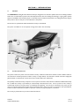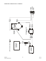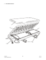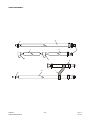
1
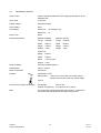
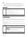
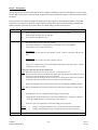
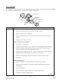
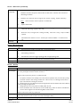
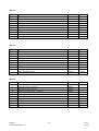
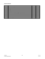
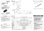
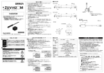
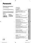
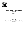
SERVICE MANUAL
LFT5508
Issue 3
VIACLIN
Alternating Pressure Mattress Overlay
Model 2502
LFT5508 - AMENDMENT RECORD
REVISION
CHANGE
NOTE
TECH.
NOTE
1
2
3
025/02
011/02
023/02
-
-
-
-
-
BRIEF DETAILS
SIGNATURE
DATE
To have a common flow restrictor assembly for 2503 &
5202
Replace part number MEC483 with MEC14753
K.Wilson
3/9/02
K.Wilson
16/9/02
K.Wilson
3/10/02
K.Wilson
22/10/02
Redrawn instruction diagrams to show overlay straps
around mattress.
Reformated Viaclin service manual 2502 so that it is
similar in structure as the newer manuals. Changed text
‘5.5 ltr/min’ to ‘6.5 ltr/min’. Added note”EXISTING 2501
OR 2502 THAT REQUIRE A REPLACEMENT
POWERUNIT WILL BE REPLACED BY A 2503 POWER
UNIT (SA242) AND AN APPROPRIATE ADAPTER (REF:
MOD KIT MOD14831)”. See IU 088/02
POLICY STATEMENT
Pegasus Ltd has a policy of continuous product improvement and reserves the right to change details presented in this
Service Manual without notice.
Tel: +44 (0) 23 9278 4200
Fax:: +44 (0) 23 9278 4250
E-mail: [email protected]
Web Site: www.pegasus-uk.com
LIST OF CONTENTS
Section
Title
1.
SAFETY STATEMENT
2.
INTRODUCTION
General
System Description
3.
SETTING UP/OPERATION
Setting Up
Profiling and Knee-Breaking
Moving the Bed and Power Cuts
CPR (Cardio Pulmonary Resuscitation)
Deflation, Removal, Carrying and Storage
Alarms and Fault Finding
4.
CONSTRUCTION OF PRODUCT
Major Elements of the System
Mattress
Power Unit
Technical Details
5.
INFECTION CONTROL AND CLEANING
Infection Control
Cleaning Guidelines
6.
EQUIPMENT MAINTENANCE
General
Power Unit
Mattress
7.
TEST EQUIPMENT
8.
PARTS LIST
Power Unit
Mattress
LTF5508
VIACLIN MODEL 2502
i
Issue 3
Oct 02
SECTION 1 - SAFETY STATEMENT
1.1.
The VIACLIN system must be used in accordance with the manufacturer's instructions.
1.2.
The mains electricity supply within the building where the VIACLIN system is to be used must comply
with IEE Regulations.
1.3.
Only personnel trained or formally approved by Pegasus Ltd in operation and maintenance of Pegasus
systems may perform maintenance, modification or repair work on Pegasus Ltd Power Control Units.
1.4.
Unqualified personnel attempting to work on Pegasus Ltd Power Control Units risk serious injury to
themselves and others, and possibly death by electrocution.
Do not work, or attempt to work on Pegasus Power Units unless you are properly qualified
to do so.
1.5.
Pegasus Ltd systems are designed to comply with all relevant electrical safety, manufacturing and
performance standards published by IS0, IEE & BSI.
1.6
Materials used for cleaning procedures may be subject to COSHH regulations - manufacturer's
Instructions for Use must be followed at all times.
1.7
Materials used for maintenance and repair may be subject to COSHH regulations - manufacturer's
Instructions for Use must be followed at all times.
LFT5508
VIACLIN MODEL 2502
1.1
Issue 3
Oct 02
SECTION 2 - INTRODUCTION
2.1
GENERAL
The VIACLIN Alternating Pressure Mattress Overlay is designed for use whenever patients have some mobility problems
and/or who are vulnerable to pressure ulcer development and/or who have existing tissue damage. It gives gentle, dynamic
support to bedridden and immobile people in recumbent, supine and knee-break postures, providing alternatively support
then pressure relief to each part of the underside of the patient.
The bed can be repositioned whilst the Mattress Overlay is still inflated.
The system is suitable for use in hospitals, nursing homes and in the community.
2.2
SYSTEM DESCRIPTION
The system consists of a power unit and a mattress overlay. Audio and visual alarms activate if a fault condition exists for
more than three minutes (compressor failure, overlay or airpipe failure). An audio alarm sounds if the mains supply fails
(disconnected or switched off). These alarms alerts medical staff to the malfunction.
The specially constructed overlay comprises a series of pairs of transverse cells, which are inflated and deflated alternately.
Air to inflate the overlay is provided by an electronically controlled power unit. The air pressure in the overlay is
continuously monitored, and the system is completely self-regulating. The overlay is connected to the power unit by
means of an airpipe which features quick release connections at the power unit end, for convenience and rapid deflation,
to allow cardiac resuscitation procedures. Operator controls are purposely kept to a minimum.
The overlay is positioned on top of the normal bed mattress.
LFT5508
VIACLIN MODEL 2502
2.1
Issue 3
Oct 02
SECTION 3 - SETTING UP/OPERATION
3.1
SETTING UP
CAUTION:
Use only on top of the existing bed mattress.
Remove the bedding from the bed.
Ensure there are no sharp objects to damage the Overlay. Place the Overlay on top of the bed mattress with the
umbilical at the foot end of the bed. Tuck the two end flaps under the bed mattress.
Secure the Overlay straps to the mattress. Do not secure to the bed frame (only secure Overlay straps loosely to the
moving parts of the bed frame, (if applicable).
LFT5508
VIACLIN MODEL 2502
3.1
Issue 3
Oct 02
Hang the power unit on the bed or place on the floor.
Connect the three airpipe connectors on to the power unit connectors. Plug the power unit into a suitable mains
socket and switch on.
The system will take approximately 20 minutes to reach full inflation pressure, at which time the green NORMAL light
will come on and the amber light will extinguish. During this start up phase the red FAULT light may come on and the
audible alarm sound, if this occurs turn the power unit off and back on again to reset the alarm.
LFT5508
VIACLIN MODEL 2502
3.2
Issue 3
Oct 02
!!ALARM!!
11
12
1
VIACLIN
10
2
8
4
Alternating Pressure Overlay
3
9
7
6
5
Once inflated, check the securing straps and tighten if required. For maximum benefit, use only one sheet loosely
placed over the mattress. If the sheet is tucked in ensure that it is left loose over the mattress to avoid hammocking.
Once a patient is placed on the mattress the system will adjust automatically to the patient characteristics
(weight/position) to provide optimum clinical benefit for each patient. The mattress may feel firm at first until it has
adjusted to the individual. Allow approximately 15 minutes for this automatic adjustment to be completed.
If the mattress does not perform as described above, please refer to Section F of this guide ‘Alarms and Fault Finding’.
3.2
PROFILING AND KNEE-BREAKING
The system may be used while the bed is in the profiled or knee-break position:
1.
With the bed in its present position, loosen or release the Overlay securing straps.
2.
Change the bed to the required position (profile or knee-break).
3.
Re-secure the securing straps.
NOTE: Straps must be attached to moving parts of the bed frame to avoid jamming the bed mechanism or stretching
the overlay.
LFT5508
VIACLIN MODEL 2502
3.3
Issue 3
Oct 02
3.3
MOVING THE BED AND POWER CUTS
CAUTION:
The patient will not receive the benefit of the VIACLIN system while it is disconnected
and the power unit is switched off. Therefore the system should be reconnected as
soon as possible once the bed has been moved to its new position.
If you need to move the bed with the Mattress Overlay still inflated or in the event of a major mains power failure,
carry out the following procedure:
1.
OVERLAY
a
b
2.
Disconnect the two red airpipes from the power unit and quickly connect together.
Disconnect the black airpipe from the power unit.
POWER UNIT
a
b.
Switch off and reset the power-down alarm. Disconnect from the mains.
The overlay will remain inflated for over 24 hours. The bed can now be moved.
LFT5508
VIACLIN MODEL 2502
3.4
Issue 3
Oct 02
3.4
CPR (CARDIO PULMONARY RESUSCITATION)
In the event of cardiac arrest, disconnect both red airpipes:
1.
While system is operating normally,
disconnect from the power unit.
2.
While moving the bed, disconnect
from each other.
3.5
DEFLATION, REMOVAL, CARRYING AND STORAGE
POWER UNIT
1.
Switch off.
2.
Silence alarm.
3.
Disconnect from mains.
4.
Disconnect all airpipes.
5.
Remove from bed.
OVERLAY
1.
Undo all securing straps.
2.
Roll up the Overlay.
LFT5508
VIACLIN MODEL 2502
3.5
Issue 3
Oct 02
3.6
ALARMS AND FAULT FINDING
ALARMS
The VIACLIN Alternating Pressure Mattress Overlay is equipped with a sophisticated set of alarm functions, these
alert the user to the status of the available mains supply and any mattress overlay defect.
In normal conditions with mains power available, the power unit turned on, the mattress overlay fully inflated and
alternating, the status light on the power unit front panel will be green.
If at any time the mains power should be removed from the power unit, an audible alarm will be heard. This audible
alarm may be cancelled by pressing the alarm reset button for approximately 2 seconds.
If the product develops a defect whilst in use, the status light will turn red and an audible alarm will be heard. This
alarm may be cancelled by turning the mains power switch on the side of the power unit to the OFF (O) position,
then pressing the alarm reset button for approximately 2 seconds.
FAULT FINDING.
SYMPTOM
ACTION
No lights on power unit
Check power unit is connected to the mains power supply
and that the power unit switch is turned to the ON (1)
position.
Status light red and alarm sounding, or alarm sounding
but no lights
Turn mains switch on power unit OFF, press alarm reset
button for approximately 2 seconds until alarm cancels, then
switch on again:
Mattress overlay not inflating, status light green
LFT5508
VIACLIN MODEL 2502
a.
If the status light does not illuminate, mains power
to the power unit has been lost. Check that the
power unit is connected to the mains supply and
that the power unit switch is turned to the ON (1)
position
b.
If the alarm clears then returns after approximately
12 minutes, check air connection between power
unit and mattress overlay, ensuring that all air
connectors are pushed fully home and that the
airpipe is not folded or bent causing air flow to be
reduced. Turn mains switch on power unit OFF,
press the alarm reset button for approximately
2 seconds until alarm cancels, then switch on again
Check all air pipes as in (b) above
3.6
Issue 3
Oct 02
SECTION 4 – CONSTRUCTION OF PRODUCT
4.1
MAJOR ELEMENTS OF SYSTEM
The product comprises two major elements:
4.2
1.
Mattress Overlay
2.
Power Unit
MATTRESS OVERLAY
The mattress has 18 transverse cells interconnected, such that there are 2 sets of cells - each being fully inflated then
fully deflated.
The cells are chemically bonded to pneumatic tubing, which is formed into a harness terminated by the CPR
connector.
The Mattress has a cover which protects the mattress and the bed base from soiling by body fluids, and has a smooth
surface finish to facilitate cleaning.
4.3.
POWER UNIT
The Power Unit comprises a housing that has a moulded lid, a base and chassis assembly that is fixed together by four
socket-headed screws that also secure the hook assembly. When closed the casing is sealed to IP44.
The lid incorporates the following:
1.
Mains switch - A double-pole, switch mounted the side wall of the casing.
2.
Alarm reset button - Fixed adjacent to the mains switch.
3.
Fuses - Two 1 Amp, anti surge fuses are fitted adjacent to the mains switch.
4.
Air connectors - There are three connectors to enable connection of the airpipe fitted to the opposite side
wall of the casing to that used for the mains switch.
5.
Front panel label - The label has a hole for the tri-coloured LED that indicates power supply on (amber),
normal running mode (green) and fault (red). The LED is connected to the integral electronic control unit
(ECU) via an IDT connector.
LFT5508
VIACLIN MODEL 2502
4.1
Issue 3
Oct 02
The base incorporates the following:
1.
Suspension hooks - To enable the unit to fit over the footboard of a bed.
2.
Air intake holes - Covered on the inside by a small block of foam that serves as a primary air filter and
protects the unit from ingress of dust.
A manufacturer's label is affixed to the rear of the base which bears electrical rating information and the serial number
of the unit.
The interior of the base carries a mild steel chassis that is secured to the casing front by two screws.
The chassis incorporates the following:
Compressor
Rotorvalve
Pressure Switch
Alarm Buzzer
LFT5508
VIACLIN MODEL 2502
ECU
Silencer / Accumulator
Restrictor Block
4.2
Issue 3
Oct 02
4.4
TECHNICAL DETAILS
Cycle Control
Purpose designed distributor valve supplying operating air to the
inflatable cells
Cycle Time
12 minutes
Supply Voltage
220/240Vac 50Hz
Power Rating
40VA
Fuse Rating
Power Unit:
1A Antisurge (x2)
Mains Plug:
3A
Noise Level
NC30
Nominal Dimensions
Mattress (Inflated)
Mattress (narrow)
Length:
1900mm
Length
1900mm
Width:
880mm
Width
800mm
Height:
130mm
Height
130mm
Weight:
3.8kg
Weight
3.5kg
Power Unit
Height:
203mm
Width:
220mm
Depth:
115mm (max)
Weight:
2.3kg
Electrical Safety
Conforms to BSEN 60601-1
Classification
Class 1, Type B
Mode of Operation
Continuous
Symbols
Alternating Current
Mains Switch - 1 (On) Power connected to the mains supply
0 (Off) Power disconnected from mains supply
Type B
Environment (Usage and Storage)
Air Humidity:
30% to 75%
Ambient Temperature: 0ºC (32ºF) to 40ºC (104ºF)
EMC
LFT5508
VIACLIN MODEL 2502
This equipment complies with EMC requirements. If effects are
noticed the affected equipment should be moved apart.
4.3
Issue 3
Oct 02
SECTION 5 – INFECTION CONTROL/CLEANING
5.1
INFECTION CONTROL
Infection Control and routine cleaning must be carried out in accordance with your local Infection Control Policy.
5.2
CLEANING GUIDELINES
WARNING:
ENSURE THE POWER UNIT IS DISCONNECTED FROM THE MAINS ELECTRICITY
SUPPLY BEFORE CLEANING.
CAUTION
Do not immerse the power unit in water.
Do not high temperature autoclave, or use Phenolic based products for cleaning.
It is recommended the system is cleaned between users or approximately every 2 weeks if in constant use.
Overlay and Cover
Wipe down with warm water containing detergent, dry thoroughly before use.
The cover may also be machine washed (80º C).
Swab with a solution of Sodium Hypochlorite or similar (1,000 to 10,000ppm available chlorine), dry thoroughly before
use.
It is recommended that the system is cleaned regularly and after each patient use.
In many cases it will only be
necessary to remove the
overlay cover for cleaning.
Where there is obvious
soiling, a full cleaning or
sterilization procedure will
have to be carried out.
Ensure overlay and cover are
fully dry before use
CAUTION:
SODIUM
HYPOCHLORITE
(1,000 - 10,000
PARTS PER
PARTS PER
MILLION
AVAILABLE
DECONTAMINATE
USING ETO
(ETHYLENE OXIDE)
OR DRAEGER
SYSTEM
COVERS ONLY
80 C
PHENOL
CAUTION
LFT5508
VIACLIN MODEL 2502
5.1
Issue 3
Oct 02
Power Unit
Wipe down with warm water containing detergent, dry thoroughly before use.
Wipe down with a solution of Sodium Hypochlorite or similar (up to 10,000ppm available chlorine), dry thoroughly
before use
CAUTION
Cleaning procedure
+
SODIUM
HYPOCHLORITE
(1,000 - 10,000
PARTS PER
MILLION
AVAILABLE
CHLORINE (Cl))
DECONTAMINATE
USING ETO
(ETHYENE OXIDE)
OR
DRAEGER
SYSTEM
CAUTION:
PHENOL
CAUTION
The overlay mattress, overlay cover and power unit may also be decontaminated by using ETO (Ethylene Oxide) or the
Draeger method.
LFT5508
VIACLIN MODEL 2502
5.2
Issue 3
Oct 02
SECTION 6 – EQUIPMENT MAINTENANCE
Overlay
To
Atmosphere
'B' Cells
'A' Cells
Rotorvalve
Motor
Gearbox
Restrictor
Block
Supply Voltage
PL5
Compressor
PL4
PL6
PL3
Supply
Voltage
2
Mains On/Running Normally
PL1
Alarm
PL2
A.C. Supply
1
ECU
From
Atmosphere
3
4
5
Pressure
Switch
6
Side Formers
7
Air
Connector
8
Tri-Colour
LED
Alarm
Reset
Buzzer
The item numbers shown at the top left hand corner of the box drawn around each item are used in the Maintenance
and Parts sections for identification purposes, i.e. Item 1 in each section is the ECU, Item 2 is the compressor, etc.
LFT5508
VIACLIN MODEL 2502
6.1
Issue 3
Oct 02
Notes:
i.
ii.
iii.
iv.
It is recommended that the Viaclin system is part of a planned preventative maintenance scheme.
To prevent damage, normal electrostatic control procedures must be observed when working on the Power
Unit.
Electrical safety checks must be carried out on completion of any routine maintenance or workshop repairs.
Details of tubing in the power unit is shown in Section 8 ‘TUBING DETAILS – SCHEMATIC’
Power Unit – General
ECU Conn
Maint/Repair
Test/Set-Up
Test Eqpt
N/A
1.
Check the security of the wiring and tightness of screws and integrity of component mountings rectify as necessary.
2.
Check pneumatic tubing for hardening or cracking and replace as necessary.
3.
Switch on the electrical power supply.
4.
Check all pneumatic connections for air leaks and rectify as necessary.
5.
Lubricate spigot outlets sparingly with appropriate grease.
Carry out an overall operation test
N/A
Item 1 – Electronic Control Unit
The microprocessor controlled ECU is mounted on the chassis.
The ECU has a rechargeable battery that provides power for the ECU and alarm buzzer in the event of power failure
(it does not provide reserve power for the compressor or rotorvalve). The battery can only be recharged by the
ECU.
Control of the compressor is by the ECU, in response to signals provided by the pressure switch which continually
monitors system pressures.
The ECU also controls the status indicator on the front panel and the alarm buzzer and responds to activation of the
alarm-reset pushbutton.
ECU Conn
Maint/Repair
N/A
The battery is the only maintainer serviceable item; otherwise the ECU is repair by replacement.
Note: To prevent damage, normal static control procedures must be observed when working on the
PMU.
Battery replacement (replacement only needed if battery is charged and power down alarm fails)
Test/Set-Up
Test Eqpt
1.
Unsolder battery from ECU – note orientation of battery.
2.
Solder new battery onto ECU, ensuring it is in the same orientation as the old battery.
Testing of the ECU is carried out as part of the system test
N/A
LFT5508
VIACLIN MODEL 2502
6.2
Issue 3
Oct 02
Item 2 – Compressor
One Air Compressor is fitted, which takes air from atmosphere within the power unit and delivers air to the overlay
bottom deck via the silencer, restrictor block, airpipe and to the top deck via the silencer, restrictor block rotorvalve
and airpipe
The Compressor has rubber-mounting feet attached by screws and nuts to an aluminium baseplate, a 4-way IDT
connector for connection to the ECU, a spigot outlet over which 8mm-diameter silicone tubing is push-fitted to
enable pneumatic connection to the check valve, from which tubing connects to the silencer.
ECU Conn
Maint/Repair
PL4
Test/Set-Up
Carry out compressor electrical tests:
1.
Disconnect tubing from the compressor (if fitted).
2.
Connect the compressor to the appropriate connector(s) on the test set (TE5315).
3.
Connect the test set to mains and switch on.
Maintenance of the compressor consists of replacing the filter:
1.
Remove the filter cover from the end of the compressor, remove the filter.
2.
Clean the filter housing surfaces and the disk.
3.
Fit a new filter and replace the cover.
No-Load Test
Check compressor runs with no excess vibration or noise - if there is a defect the 1.6a fuse may
blow.
On-Load Test
This test is carried out at the same time as the flow rate test.
Carry out a compressor flow rate test with TE5315 connected as for the no-load test - if there is
a Defect the 1.6a fuse may blow.
Carry out a flow rate test on the compressor:
Note: Ensure the compressor is in its ‘HOT’ state prior to carrying out the test:
Start Service Mode and press the Alarm Reset button once, this will start the compressor. Let the
compressor run for 30 minutes to get to the 'Hot' state.
If the system has been running for at least 1 hour prior to starting Service Mode, the compressor
is assumed to be in the 'Hot' state and do not need to be run for 30 minutes.
1.
Remove the tubing from the compressor and connect the test equipment (TE4540) in its place.
Note: Ensure Test Equipment is connected to the pressure outlet of the compressor, not the vacuum
side.
2.
3.
4.
Notes:
Test Eqpt
Switch the power unit On. Adjust the aneroid sphyg to read 100mmhg.
Check the flow rate on the flow meter reads not less than 5.5 ltr/min. If using test equipment
other than TE4540, the flow rate should read 7 ltr/min or greater.
Switch off, remove test equipment; reconnect the tubing to the compressor.
i.
ii.
If using a 1-12 ltr glass tubed flow meter, read the value from the top of the float.
If using a plastic bodied flow meter, read the value from the centre of the float.
TE4540, TE5315
LFT5508
VIACLIN MODEL 2502
6.3
Issue 3
Oct 02
Item 3 - Silencer
The silencer smoothes pressure fluctuations in the pneumatic system and absorbs any noise being carried in the
airflow from the compressor.
It is fitted into a recess in the chassis and held in place by the casing.
Spigot outlets from the silencer have 8mm-diameter silicone tubing push-fitted to enable pneumatic connection to the
compressor and restrictor block.
ECU Conn
Maint/Repair
N/A
1.
There are no maintenance actions to be carried out on the silencer. Repair is by replacement
Test/Set-Up
2.
It is recommended the silencer is replaced annually
There are no tests to be carried out on the silencer.
Test Eqpt
N/A
Item 4 – Restrictor Block
The restrictor block enables airflow to and from the following:
Silencer
Pressure Switch
Air Connector (for side formers only)
Rotorvalve
ECU Conn
Maint/Repair
Test/Set-Up
Test Eqpt
N/A
Remove all tubing from restrictor block and ensure all spigots are clear of obstructions.
There are no tests to be carried out on the restrictor block.
N/A
LFT5508
VIACLIN MODEL 2502
6.4
Issue 3
Oct 02
Item 5 – Pressure Switch
The plastic bodied pressure switch is an integral part of the rotorvalve unit. The pressure at which the switch trips
can be adjusted and set by a means of a knurled nut.
The pressure switch is a single pole electrical switch, actuated via a diaphragm that responds to the system air
pressure.
Electrical connections to the ECU are via an IDT connector.
ECU Conn
Maint/Repair
Test/Set-Up
Test Eqpt
PL3
The only replaceable part of the pressure switch is the micro switch.
1.
Disconnect electrical connections and tubing, then remove the rotorvalve assembly from the
power unit
2.
Undo the two screws securing the motor/gearbox to the base plate and swivel the motor
through 180o to allow access to the four screws securing the pressure switch cover to the base
plate.
3.
Remove the thumbscrew, plastic collar and spring from the pressure switch pillar, noting the
orientation of the collar.
4.
Remove the screws securing the pressure switch cover and remove the cover and actuating plate,
taking care not to disturb the pressure sac. Remove the actuating plate from the cover.
5.
Remove the rubber sleeve from the top, front microswitch connector. Using a 1.5mm Allen key,
remove the two grub screws securing the micro switch to the cover and remove the micro
switch.
6.
Replace the microswitch and secure in place using the grub screws removed at (5). Replace the
rubber sleeve on the top front connector.
7.
Refit the actuating plate into the cover, ensuring the flat side is away from the micro switch.
8.
Taking care not to disturb the pressure sac, replace the pressure switch cover ensuring the
actuating plate fits over the pillar. Secure the cover using the screws removed at (4).
9.
Replace the spring, plastic collar and thumbscrew on the pillar ensuring the collar is oriented as
noted in (3).
10.
Swivel the motor/gearbox through 180o and secure in place using the screws removed at (2).
11.
Refit the rotorvalve assembly in the power unit. Reconnect the electrical connections and tubing.
12.
Carry out a pressure test.
Carry out pressure test
1
Fit an aneroid sphyg (TE004) to each line of test connector (TE4827)
2
Fit test connector between power unit and airpipe.
3
Set the pressure switch to attain cell pressures of 40-50mmHg.
Ensure the pressure switch operates at 40mmHg (nominal) on the fall.
TE4827, TE004 (x3)
LFT5508
VIACLIN MODEL 2502
6.5
Issue 3
Oct 02
Item 6 – Rotorvalve
The rotorvalve is a rotary pneumatic valve that enables airways to open and close as the rotor turns, thereby enabling
air to be fed to and from the overlay. It is driven by an integral motor/gearbox.
Pressure Switch
Rotor and Stator
(matched pair)
Drive/Retaining Pin
Motor/Gearbox
Silencer
Compression
Spring
ECU1 Conn
Maint/Repair
PL5
Remove Rotorvalve Assembly
1.
Disconnect the tubing from the restrictor block and airpipe connectors.
2.
Disconnect the motor lead from ECU PL5.
3.
Undo the 3 screws securing the Rotorvalve to the chassis. Remove the rotorvalve assembly
complete.
4.
Replacement is the reverse of the above.
Replace rotorvalve rotor and stator
1.
Remove silencer from rotorvalve
2.
Axially depress the Rotorvalve rotor and slide the rotor drive/retaining pin along the slot in the
top face of the Rotor, until the pin is clear of the gearbox drive shaft. The rotor, stator and
compression spring can then be slid axially off the drive shaft.
3.
Fit the compression spring, stator and rotor, in order, on to the drive shaft. Depress the rotor,
aligning the slot in its top face with the transverse hole in the drive shaft.
4
Reinsert the drive/retaining pin through the drive shaft and release pressure on rotor.
5.
Refit silencer.
Replace Motor/Gearbox
1.
Remove rotorvalve (see - replace rotorvalve rotor and stator. Paras 1 and 2)
2.
Undo two screws securing the motor/gearbox to pressure switch base plate and remove
motor/gearbox.
3.
Fit new motor/gearbox.
4.
Re-fit rotorvalve (see - replace rotorvalve rotor and stator. Paras 3 to 5)
5.
Test Rotorvalve operation as detailed below.
continued ….
LFT5508
VIACLIN MODEL 2502
6.6
Issue 3
Oct 02
Item 6 – Rotorvalve (continued)
Maint/Repair
(continued)
Rotorvalve Maintenance/Repair
1.
Check the rotorvalve airways are clean and clear of obstruction - wash the rotor and stator in
mild detergent solution.
2.
Check the rotor and stator faces for signs of wear and tear or pitting. Replace if necessary
Note:
Test/Set-up
Rotor and stator must be replaced as a matched pair.
3.
Replace silencer filter
1.
Switch on the power unit and ensure that the Rotorvalve is cycling (the tone of air escaping from the
outlet tubes will change regularly if all is well).
2.
Ensure the rotor, motor/gear box is running smoothly. If the rotor is noisy, a major overhaul is
required.
3.
Check Rotorvalve rotation is correct - one full cycle of mattress inflation = 12 minutes ± 0.5
min.
Test Eqpt
N/A
Item 7 – Air Connectors
ECU Conn
Maint/Repair
Test/Set-Up
Test Eqpt
N/A
1.
Check connectors visually for obvious signs of wear/specific damage.
2.
Check locking mechanisms
3.
Lubricate the connector spigots sparingly with an appropriate grease
Connect the airpipe to the power unit and run the system, check for any air leaks.
(this check should be carried out at the same time as the mattress check)
N/A
Item 8 – Overlay
ECU Conn
Maint/Repair
N/A
1. Check visually for obvious signs of wear/specific damage.
2. Carry out airpipe connector checks as for Item 7
Repair of the top deck is by the use of replacement cells:
1. To implant a cell insert, first carefully remove the connector (Roberts valve) from the cell by cutting
around the connector base, leaving a circular hole. Take care not to cut through into the bottom
layer of the cell when removing the connector.
2. Roll the insert into a long thin tube and pass through the hole into the defective cell, with its Roberts
valve protruding through the hole.
3. Gently inflate the insert and position it carefully within the cell.
4. Secure the Roberts valve of the cell insert to the cell wall using a washer of mattress material fitted
over the valve and glued to the cell wall using UPVC solvent cement.
Test/Set-Up
Test Eqpt
Repair of the bottom deck is by replacement.
Connect the overlay to the power unit and run the system, check for any air leaks.
(this check should be carried out at the same time as the airpipe check)
N/A
LFT5508
VIACLIN MODEL 2502
6.7
Issue 3
Oct 02
SECTION 7 – TEST EQUIPMENT
TE004
TE4827
-30 to 100mmHg
GAUGE
20
CELL SET IDENTIFIER
40
60
B
0
80
-30
H
A
100
TE IDENTIFIER
H
TE4827
mm.Hg
RESTRICTOR
TE4540
FLOWMETER
-30 to 100mmHg
GAUGE
20
40
60
0
80
-30
'T' PIECE
mm.Hg
100
RESTRICTOR
HOSE TAIL
TO
COMPRESSOR
SILENCER
TE5315
4 WAY
N
L
240 Vac
4 WAY
COMPRESSOR TEST EQUIPMENT
TE 5315
ON/OFF
MOLEX
4 WAY
MOLEX
4 WAY
This equipment must not be opened or adjusted
by unauthorised personnel.
Pegasus Limited
Pegasus House, Waterberry Drive, Waterlooville,
Hampshire. PO7 7XX,
England
Tel: +44 (0)23 9278 4200 Fax: +44 (0)23 9278 4250
FUSE 1.6A
Made in the United Kingdom
LFT5508
VIACLIN MODEL 2502
MAINS
INPUT
7.1
Issue 3
Oct 02
SECTION 8 – PARTS LIST
1. POWER UNIT ASSEMBLY – SA200/6
NOTE: EXISTING 2501 OR 2502 THAT REQUIRE A REPLACEMENT POWERUNIT WILL BE
REPLACED BY A 2503 POWER UNIT (SA242) AND AN APPROPRIATE ADAPTER (REF: MOD KIT
MOD14831
B
C
A
ITEM
DESCRIPTION
PART No
QTY
A
Front Cover Assembly
SA226/5
1
B
Back Cover Assembly
SA205
1
C
Chassis Assembly
NOT SPARED
1
LFT5508
VIACLIN MODEL 2502
8.1
Issue 3
Oct 02
FRONT COVER ASSEMBLY
A
R
Q
H.I.J
K
C
B
D
L
E
G
N, O, P
F
M
ITEM
DESCRIPTION
PART No
QTY
A
Front Cover Assembly
SA226/5
1
B
Label, CPR/Reanimation
LAB5476
1
C
Fuse 1A Anti-Surge
MSE1185
2
D
Strain Relief Bush
MSM1819
1
E
Female Connector
MSM4130
1
F
Male Connector Large
MSM4131
1
G
Male Connector Small
MSM4524
1
H
Mains Switch
CON4549
1
I
Splashproof Switch Cover
MSM4835
1
J
Switch Bezel
MSM4836
1
K
Reset Pushbutton (c/w Loom)
MSM5362
1
L
Mains Cable Assembly
SA228
1
M
‘O’ Ring (large male connector)
MSM4217
1
N
‘O’ Ring (small male connector)
MSM4666
1
O
Stepped Washer (outside)
MEC4518
1
P
Washer M12, Nylon (inside)
MSM4519
1
Q
LED Loom Assembly
MSM5357
1
R
Label Front
LAB4387
1
Label ‘DO NOT SWITCH OFF’ (mains plug)
LAB427
1
NOT
SHOWN
LFT5508
VIACLIN MODEL 2502
8.2
Issue 3
Oct 02
REAR COVER ASSEMBLY
E
F
C
A
D
B
ITEM
DESCRIPTION
PART No
QTY
A
Rear Cover
SA205
1
B
Filter
MEC1605
1
C
Vinyl Cover for Hooks
MSM4127
2
D
Rear Label
LAB5449
1
E
Screw
SCR452
4
F
Washer
WAS361
4
LFT5508
VIACLIN MODEL 2502
8.3
Issue 3
Oct 02
CHASSIS ASSEMBLY
G
L
F
H
A
N
K
B
M
I
C
E
D
J
ITEM
DESCRIPTION
PART No
QTY
A
Compressor Assembly
SA213
1
B
Nylon Bush
MSM4113
1
C
Rotorvalve Assembly
RV801
1
D
ECU Insulating Sheet
MEC4173
1
E
ECU
SA220/1
1
F
Restrictor Block Assembly
SA207
1
G
Silencer Assembly
SA208
1
H
Compressor Securing Screw
SCR4873
4
I
Rotorvalve Assembly Securing Screw
SCR4178
3
J
ECU Securing Screw
SCR466
4
K
Chassis Securing Screw
SCR467
2
L
Buzzer Securing Screw
SCR466
1
M
Buzzer (c/w loom)
MSM5356
1
N
Double-Sided Tape
MSM4497
1 roll
LFT5508
VIACLIN MODEL 2502
8.4
Issue 3
Oct 02
COMPRESSOR ASSEMBLY
B
A
ITEM
C
DESCRIPTION
PART No
QTY
A
Filter
MEC3024
1
B
‘O’ Ring
MSM3073
1
C
Filter Cover (c/w ‘O’ Ring)
MLD3075
1
ROTORVALVE ASSEMBLY
C
A, B
D
F
E
ITEM
DESCRIPTION
PART No
QTY
A
Pressure Switch
MEC5087
1
B
Pressure Switch Microswitch
MSE4450
1
C
Motor/Gearbox
MOT5561
1
D
Rotorvalve Rotor and Stator (matched pair)
RV5086
1
E
Silencer (c/w foam insert)
MLD1650
1
F
Foam Insert
MEC1605
1
LFT5508
VIACLIN MODEL 2502
8.5
Issue 3
Oct 02
SILENCER ASSEMBLY
ITEM
DESCRIPTION
PART No
Silencer Box
MLD209
QTY
1
RESTRICTOR BLOCK ASSEMBLY
A
B
ITEM
C
DESCRIPTION
PART No
QTY
A
Restrictor Block
MEC817
1
B
Spigot
MEC490
4
C
Blanking Plug
MSM492
1
ECU
A
PL2
BT1
PL4
PL3
PL1
PL5
PL6
ITEM
A
DESCRIPTION
PART No
Battery
LFT5508
VIACLIN MODEL 2502
MSE1760
8.6
QTY
1
Issue 3
Oct 02
LFT5508
VIACLIN MODEL 2502
8.7
SILENCER
ASSEMBLY
PIP756
50mm
CHECK
VALVE
PIP756
170mm
COMPRESSOR
ASSEMBLY
NOTE: All tubing lengths to be
3mm
PIP756
150mm
PIP756
50mm
RESTRICTOR BLOCK
ASSEMBLY
ROTORVALVE
ASSEMBLY
PIP756
260mm
70mm
PIP756
PIP756
260mm
PIP756
150mm
BACK
CENTRE
FRONT
POWER UNIT TUBING DETAILS – SCHEMATIC
Issue 3
Oct 02
2. MATTRESS OVERLAY
A
B
C
E
D
F, G
LFT5508
VIACLIN MODEL 2502
8.8
Issue 3
Oct 02
880mm
ITEM
DESCRIPTION
PART No
QTY
Overlay Assembly
SA201
A
Cover
SA217
1
B
Overlay Top
MAT4124
1
C
Overlay Bottom
MAT4125
1
D
Strap Set
MAT4169
1
E
Locating Loop
MAT4190
2
F
Airpipe Assembly
SA202
1
G
Airpipe Cover
SA218/2
1
800mm
ITEM
A
B
C
D
E
F
G
DESCRIPTION
Overlay Assembly
Cover 800mm
Overlay Top 800mm
Overlay Bottom 800mm
Strap Set 800mm
Locating Loop 800mm
Airpipe Assembly 800mm
Airpipe Cover
PART No
SA201/3
SA217/3
MAT5475
MAT5477
MAT5478
MAT4190
SA202/1
SA218/2
QTY
PART No
SA201/4
SA217/4
MAT5505
MAT5506
MAT5507
MAT4190
SA202/2
SA218/2
QTY
1
1
1
1
2
1
1
680mm
ITEM
A
B
C
D
E
F
G
DESCRIPTION
Overlay Assembly
Cover
Overlay Top
Overlay Bottom
Strap Set
Locating Loop
Airpipe Assembly
Airpipe Cover
LFT5508
VIACLIN MODEL 2502
8.9
1
1
1
1
2
1
1
Issue 3
Oct 02
AIRPIPE ASSEMBLY
A
H
C
J
G
F
B
D
I
H
LFT5508
VIACLIN MODEL 2502
E
8.10
Issue 3
Oct 02
800mm
ITEM
DESCRIPTION
PART No
QTY
A
Red Airpipe (male connector)
SA202/3
1
B
Red Airpipe (female connector)
SA202/4
1
C
Black Airpipe (male connector)
SA202/5
1
D
Black Airpipe (female/female connectors)
SA202/6
1
E
‘O’ Ring (male connectors)
MSM4217
2
F
‘T’ Connector
MSM744
1
G
Elbow Connector
MSM745
1
H
Straight Connector
MSM748
2
I
Retaining Strap
MAT4180
J
Tubing PVC Black 3/8 I/D
PIP1959
1
640mm
800mm
ITEM
DESCRIPTION
PART No
QTY
A
Red Airpipe (male connector)
SA202/3
1
B
Red Airpipe (female connector)
SA202/4
1
C
Black Airpipe (male connector)
SA202/5
1
D
Black Airpipe (female/female connectors)
SA202/6
1
E
‘O’ Ring (male connectors)
MSM4217
2
F
‘T’ Connector
MSM744
1
G
Elbow Connector
MSM745
1
H
Straight Connector
MSM748
2
I
Retaining Strap
MAT4180
1
J
Tubing PVC Black 3/8 I/D
PIP1959
560mm
680mm
ITEM
DESCRIPTION
PART No
QTY
A
Red Airpipe (male connector)
SA202/3
1
B
Red Airpipe (female connector)
SA202/4
1
C
Black Airpipe (male connector)
SA202/5
1
D
Black Airpipe (female/female connectors)
SA202/6
1
E
‘O’ Ring (male connectors)
MSM4217
2
F
‘T’ Connector
MSM744
1
G
Elbow Connector
MSM745
1
H
Straight Connector
MSM748
2
I
Retaining Strap
MAT4180
1
J
Tubing PVC Black 3/8 I/D
PIP1959
LFT5508
VIACLIN MODEL 2502
8.11
445mm
Issue 3
Oct 02
MISCELLANEOUS
ITEM
DESCRIPTION
PART No
QTY
Check Valve Assembly
SA238
1
Check Valve
MSM5031
1
Tubing Silicone 5x8mm
PIP756
as required
Tubing PU Clear 1/8x1/4
PIP788
as required
Tie-Wrap Base
MSM347
as required
Tie-Wrap, small
MSM550
as required
Tape Marine PVC Black (for strapping the airpipes together)
MSM4191
as required
Loom, Mains/ECU
MSM5359
1
Loom, Reset Button/Earth
MSM5360
1
Loom, LED/Earth
MSM5361
1
Loom, Mains/Fuses
MSM5363
1
Overlay Carry Bag
MAT5404
as required
LFT5508
VIACLIN MODEL 2502
8.12
Issue 3
Oct 02
PEGASUS LIMITED
Pegasus House
Waterberry Drive Waterlooville Hampshire
PO7 7XX England
Tel: +44 (0) 23 9278 4200
Fax: +44 (0) 23 9278 4250
E-Mail: [email protected]
Website: www.pegasus-uk.com
PEGASUS
and the associated device marks are Trademarks of Pegasus Limited.
Pegasus Limited has a policy of continuous product improvement and reserves
the right to amend specifications presented in this brochure.
0120
Publication Reference: LFT5508 Issue 3
© Pegasus Ltd, England, 2002