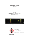
1
SERVICE MANUAL Automated Blood Coagulation Analyzer CA-500 Section 1 Specifications Section 2 Hydraulics and Mechanics Section 3 Electronics Section 4 Adjustment Section 5 Service Program Section 6 Error Messages and Troubleshooting Section 7 Schematics Appendix A Parts List Appendix B Installation Appendix C Disassembly SYSMEX CORPORATION KOBE, JAPAN SYSMEX CORPORATION, TECHNO CENTER 4-4-4 Takatsukadai, Nishi-ku, Kobe 651-2271, Japan TELEPHONE: 81-78-991-1911 FAX: 81-78-992-3274 URL=http://www.sysmex.co.jp SYSMEX AMERICA, Inc. 1 Nelson C. White Parkway, Mundelein IL 60060, U.S.A. TELEPHONE: 1-847-996-4500 FAX: 1-847-996-4505 URL=http://www.sysmex.com/ SYSMEX UK LIMITED Sunrise Parkway, Linford Wood (East), Milton Keynes, Buckinghamshire, MK14 6QF, U.K. TELEPHONE: 44-1908-669555 FAX: 44-1908-669409 SYSMEX EUROPE GmbH Bornbarch 1 22848, Norderstedt, Germany TELEPHONE: 49-40-527260 FAX: 49-40-52726100 SYSMEX SINGAPORE PTE LTD. 2 Woodlands Sector 1, #01-06, Woodlands Spectrum Singapore 738068 TELEPHONE: 65-221-3629 FAX: 65-221-3687 Copyright © 1999 through 2001 by SYSMEX CORPORATION First Edition Second Edition November 1999 December 2001 All right reserved. No part of this book may be reproduced in any form or by any electronic or mechanical means, including information storage and retrieval systems, without written permission from the publisher. Printed in Japan Part Code Number Printed Manual: 601-8244-3 CD-ROM Manual: 601-8268-2 SECTION 1 SPECIFICATIONS To Cover 1.1 Outline ..................................................................................................................................................1-1 1.2 Name and Model ..................................................................................................................................1-1 1.3 Configuration and Dimensions .............................................................................................................1-1 1.3.1 Configuration and Expandability of the System.......................................................................1-1 1.3.2 Power Source..........................................................................................................................1-2 1.3.3 Dimensions and Weight ..........................................................................................................1-2 1.3.4 Each Unit Function and Operation ..........................................................................................1-2 1.3.5 Principles of Measurement......................................................................................................1-3 1.4 Performance, Intended Use and Effectiveness ....................................................................................1-3 1.4.1 Intended Use ...........................................................................................................................1-3 1.4.2 Performance............................................................................................................................1-3 1.4.3 Functions.................................................................................................................................1-9 1.5 Acoustic Noise Level ..........................................................................................................................1-13 1.6 Environmental Conditions...................................................................................................................1-14 1.6.1 Operating Environment .........................................................................................................1-14 1.6.2 Reagents to be used .............................................................................................................1-14 1.7 How to Operate ..................................................................................................................................1-15 CA-500 Series S/M Revised December 2001 8 SECTION 1 SPECIFICATIONS 1.1 OUTLINE The Sysmex CA-500 Automated Blood Coagulation Analyzer obtains clotting times by detecting changes in scattered light intensity reflected from a diluted sample with buffer reagent which are illuminated by red light of LED. Incubated plasma taken from the centrifuged sample blood is rapidly mixed with warmed reagent and coagulation is performed and analyzed. Its result can be automatically displayed and printed. In accordance with the way of coagulation the chromogenics substrate method and the method of immunoassay are optionally available on this unit . 1.2 NAME AND MODEL Name: Model: AUTOMATED BLOOD COAGULATION ANALYZER CA-510, CA-520, CA-530, CA-540, CA-550, CA-560 1.3 CONFIGURATION AND DIMENSIONS 1.3.1 Configuration and Expandability of the System (1) Configuration 1) Main Unit (including Sampler Unit, Pneumatic Unit and Built-in Printer) 2) Chromogenic Unit and Bar Code Reader can be connected according to the following combinations as the factory option. Reagent Cooler Unit Chromogenic Unit CA-510 – – CA-520 – – CA-530 O O CA-540 O O CA-550 O O CA-560 O O * 575 nm is used for Immunoassy. Immunoassay – – – – O* O* Bar Code Reader Option O Option O Option O (2) Factory Option 1) ID Bar Code Reader (optional supply is available for CA-510 and CA-530) Sample ID numbers can be automatically read by Built-in Type Bar Code Reader (built in the sampler unit), which can scan the samples in one rack and the STAT sample. (CA-520, CA-540) 2) Chromogenic Unit The chromogenic analysis is available on Chromogenic Unit built in Main Unit. (CA-530, CA-540) 3) Immunoassay Unit The immunoassay is available on Immunoassay Unit built in Main Unit. (CA-550, CA-560) 4) Reagent Cooler Unit Cooling reagent (for four parameters) is available on Reagent Cooler Unit built in Main Unit. (CA-530, CA-540) (3) Interface with Other Instruments 1) RS-232C 2) PC-DPS(C), CA-DPS, SIS, or Host Computer can be connected. CA-500 Series S/M 1-1 Revised December 2001 8 1.3.2 Power Source (1) Rated voltage AC 100 V/117 V ± 10% AC 230 V ± 15% (2) Type of Current Direct Current (3) Frequency 50 or 60 Hz (4) Maximum power consumption Unit Main Unit (5) 1.3.3 CA-510 310 VA or less CA-520 320 VA or less CA-530 380 VA or less CA-540 400 VA or less Dimensions and Weight Dimensions (excluding projections) 540 mm (width) X 487 mm (height) X 470 mm (depth) ± 3% respectively (2) Weight Unit Main Unit (1) (2) (3) (4) (5) (6) (7) (8) (9) (10) (11) (12) (13) CA-560 400 VA or less Class and Type of Electrical Protection Class-I electrical apparatus, Type-B electrical apparatus (1) 1.3.4 CA-550 380 VA or less CA-510 43 kg CA-520 44 kg CA-530 44 kg CA-540 45 kg CA-550 44 kg CA-560 45 kg Each Unit Function and Operation Main Unit Power Switch Turns the power ON/OFF Display Unit Displays the analysis registrations, analysis results, stored information and operation contents on the LCD. Control Unit Using LCD and Touch Panel, controls the operation in dialog. XYZ Drive Mechanism Dispenses sample and reagent. Transfers the reaction tubes. Mechanical Stop Switch Stops the operation temporary. Detector Block Determines the coagulation time by measuring changes in the intensity of light scattered by increasing turbidity. Chromogenic Unit Detects the changes in the light absorbance by the transmitted light. Immunoassay Unit Detects the changes in the light absorbance by the transmitted light. Temperature Control Unit Controls temperatures for Detector Block, Reagent Heater Section and Cooling Section. System Control Unit Controls Main Unit system. Drive Circuit Unit Controls each motor ‘s driving. Pneumatic Unit Sampler Unit Enables the continuous automatic operations by the sampler. One sampler rack can contain 10 sample tubes. CA-500 Series S/M 1-2 Revised December 2001 8 1.3.5 Principles of Measurement 1.3.5.1 Biological Activation Method (1) Coagulation Reaction Detection Method (Scattered Light Measuring Method): Red light (660 nm) is irradiated onto the mixture of plasma and reagent and the change of the scattered light is detected, corresponding to the turbidity change when the fibrinogen is converted to fibrin. (2) Coagulation End-Point Detection Method (Percent Detection Method): Let the scattered light intensity at the time when the coagulation reagent is added to be 0% and that when the coagulation reaction is completed to 100. The coagulation time is obtained from the time to reach the presumed percent of the coagulation curve. 1.3.5.2 (1) Chromogenic Substrate Method Calorimetric Method Rate Method 1.4 PERFORMANCE, INTENDED USE AND EFFECTIVENESS 1.4.1 Intended Use This unit measures the coagulation of the plasma or serum component of anti-coagulant (sodium citrate) added human blood. 1.4.2 (1) Performance Measurement Parameters and Display Parameters (Default Unit is shown in [ ]). 1) 2) Prothrombin Time (PT) [second] Calculated Parameters: (a) Prothrombin Activation Percent (b) Prothrombin Ratio (c) International Normalized Ratio (INR) (d) Derived Fbg (for export specification only) [%] [–] [ INR ] [mg/dL] Activated Partial Thromboplastin Time (APTT) [second] Calculated Parameters: (a) APTT Ratio (b) Activation Percent (for European and UK specifications only) 3) 4) Fibrinogen (Fbg) [–] [% ] [second] Calculated Parameters: (a) Fibrinogen Concentration [mg/dL] Thrombo Test (Plasma Method) [second] Calculated Parameters: (a) Activation Percent (b) INR (for European and UK specification only) CA-500 Series S/M 1-3 [%] [–] Revised December 2001 8 5) Normotest (NT) [second] Calculated Parameters: (a) Activation Percent (b) INR (for European and UK specification only) [%] [–] 6) Thrombin Time (for export specifications only) [second] 7) Factor (II, V, VII, VIII, IX, X, XI, XII) [second] Calculated Parameters: (a) Activation Percent 8) [%] Protein C Coagulum (PCc) [second] Calculated Parameters: (a) Activation Percent (9) [%] Batroxithonbin (BXT) [second] (10) LA1, LA2 [second] [Options] (11) (12) (13) (14) (15) Anti-thrombin III (AT-III) α2 Anti-plasmin (APL) Anti-plasminogen (Plg) Protein C (PC) Heparin (Hep) International Unit (16) FDP (SFDP) (17) Plasma FDP (PFDP) (18) D-Dimer (DPI/DD) (2) [%] [%] [%] [%] [%] [IU/mL] [µg/mL] [µg/mL] [g/mL] [µg/mL] Measurement Ranges 1) Fbg Measuring is possible from 25 mg/dL to 1000 mg/dL of the fibrinogen concentration. (In case of 450 mg/dL or above, measurement is performed with automatic re-dilution in high Fbg concentration mode, and in case of 50 mg/dL or less, in low Fbg concentration mode. In CA-550 and CA-560, measurement for 900 mg/dL or above is performed in high Fbg concentration mode, and for 100 mg/dL or less, in low Fbg concentration mode. ) 2) D-Dimer (CA-550 and CA-560 only) With applicable reagents, measuring is possible from 50 to 9999 µ/gL. However, the concentration of 2000 µ/gL or above is measureed in 8-hold dilution mode (+D-Dimer). 3) Serum FDP(CA-550 and CA-560 only) With applicable reagents, measuring is possible from 2.5 to 320 µg/mL . However, the concentration of 40 µg/mL or above is measureed in 8-hold dilution mode (+PFC). 4) Plasma FDP (CA-550 and CA-560 only) With applicable reagents, measuring is possible from 2.5 to 480 µg/mL. However, in the concentration of 60 µg/mL or above, measurement is performed in 8-hold dilution mode (+PFC). CA-500 Series S/M 1-4 Revised December 2001 8 (3) Measurement Time 1) Maximum Measurement Time in Standard Mode PT 100 seconds (120 seconds in CA-550 and CA-560) Fbg 100 seconds Others 190 seconds ATIII 30 seconds 2) (4) Maximum Measurement Time in Automatic Extended Mode All Parameters 600 seconds Accuracy When control plasma N is measured consecutively 10 times, measurement error of the average time (second) should lie within the following ranges. (The ambient temperature must be 25 ± 10°C.) PT APTT (5) ± 8% or less ± 8% or less Reproducibility Coefficient of variation, when control plasma N is measured consecutively 10 times, should lie within the following ranges with 95 % confidence if specified reagents are used. The ranges should be observed when measuring was performed on 10 to 30 µg/mL of diluent sample with SFDP and PFDP, and on 500 to 1000 µg/mL of diluent sample with D-Dimer. PT, APTT [second] CV within 2% TTO, NT [second] CV within 4% Fbg [second] CV within 4% Factor (II, V, VII, VIII, IX, X, XI, XII) [second] CV within 5% TT [second] CV within 10% BXT [second] CV within 4% LA1/LA2 [second] CV within 4% PCc [second] CV within 5% AT-III [%] CV within 5% APL [%] CV within 5% Plg [%] CV within 5% BCPC [%] CV within 5% Hep [IU/mL] CV within 5% SFDP [µg/mL] CV within 10% PFDP [µg/mL] CV within 10% D-Dimmer [µg/L] [µg/mL] CV within 10% CA-500 Series S/M 1-5 Revised December 2001 8 (6) Stability 1) Temperature Stability Variation of measurement (Activation % for AT III) at 15°C (C15) or 35°C (C35) from that at 25°C (C25) lies within the following ranges, when this formula is used. C15 (or C35) - C25 x 100 C25 PT, APTT (second) Fbg, TTO, HpT (second) AT III (%) D-Dimmer (µg/L) 2) ± 8% or less ± 10% or less ± 10% or less ± 10% or less Stability within-a-day Variation of measurement (Activation % for AT III) at the time of 2, 4 and 8 hours from that at 30 minutes after the power is turned on (initial value) lies within the following ranges. The ambient temperature at the time of measurement should be within the specified range. Temperature variation must be within 5°C. ( Measurement after 2, 4 or 8 hours ) - ( Measurement at 30 minutes ) x 100 ( Measurement at 30 minutes ) PT, APTT (second) Fbg, TTO, HpT (second) AT III (%) D-Dimmer (µg/L) 3) ± 8% or less ± 10% or less ± 10% or less ± 10% or less Long-term Stability (daily variation) Variations in measurement values (Activation % for AT III) during the continuous 10 days lie within the following ranges. The ambient temperature at the time of measurement should be within the specified range. Temperature variation must be within 5°C. ( Measurement after second day ) - ( Mean Measurement ) x 100 ( Mean Measurement ) PT, APTT (second) Fbg, TTO, HpT (second) AT III (%) D-Dimmer (µg/L) 4) ± 8% or less ± 10% or less ± 10% or less ± 10% or less Stability against Power Source Variation Variation of measurement (Activation % for AT III) lies within the following ranges when the rated voltage changes at ±10%. ( Measurement at +10% or -10% ) - ( Measurement at rated voltage ) x 100 ( Measurement at rated voltage ) PT, APTT (second) Fbg, TTO, HpT (second) AT III (%) D-Dimmer (µg/L) CA-500 Series S/M 1-6 ± 8% or less ± 10% or less ± 10% or less ± 10% or less Revised December 2001 8 (7) Analysis Mode and Sample Throughput 1) Analysis Mode 5 parameters are selected out of 7 parameters (14 parameters in CA-550 and CA-560) to perform random analysis. 2) Sample Throughput Maximum Throughput: Mean Throughput (PT, APTT, Fbg): approx. 54 tests/hour (when PT single parameter is measured) approx. 40 tests/hour (when three parameters are measured at the same time) Mean throughput in this case means the mean throughput at the point of which an hour has passed from a Start-key entry. (8) Time Resolution 1) Coagulation Time resolution is as follows depending on the elapsed time from the start of measurement. 2) 0.1 second 2 through 120 seconds 0.2 second 120 through 240 seconds 1.0 second 240 through 600 seconds Chromogenics Substrate Method and Immunoassay Method The unit can continue performing sampling every second up to 600 seconds at maximum. (9) Compensation functions 1) Setting of Coagulation Detection End Point The coagulation detection point can be set every 1% within the range of 2 to 80%, enabling the data calibration. 2) External compensation Function The measured data is corrected with the linear equation. (10) Required Volume of Plasma and Reagent The required sample amount for each parameter and the required volume of reagent for the measurement of one sample are shown below. (Unit in µL) Parameter (1) PT (2) APTT (3) Fbg (4) TTO (5) HpT (6) TT (7) II, V, YII, X CA-500 Series S/M Sample/Reagent Citrated Plasma Pt Citrated Plasma Aptt CaC12 Citrated Plasma Owren’s Veronal buffer Fbg Citrated Plasma Owren’s Veronal buffer CA-Series Comlex Factor TTO Citrated Plasma Owren’s Veronal buffer CA-Series Complex Factor HPT Citrated Plasma Owren’s Veronal buffer Citrated Plasma Owren’s Veronal buffer Factor Deficient Plasma PT 1-7 Quantity 50 100 50 50 50 5 95 50 20 30 125 10 40 125 100 50 5 45 50 100 (Continues to the next page.) Revised December 2001 8 Parameter (8) VII, IX, XI, XII (9) PC.c (10) BXT (11) La1 La2 (12) AT3 (13) APL (14) Plg (15) BCPC (16) Hep (17) DDPI AdDD (18) DD (19) SFDP (20) PFDP (in 800 nm analysis) (21) PFDP (in 575 nm analysis) (Continued from the previous page.) Sample/Reagent Quantity Citrated Plasma 5 or 10 Owren’s Veronal buffer 45 or40 Factor Deficient Plasma 50 APTT 50 Calcium Chroride 50 Citrated Plasma 5 Protein C Deficient Plasma 35 Protein C Activator 40 APTT 40 Calcium Chloride 40 Citrated Plasma 50 Batroxobin 100 Citrated Plasma 100 LA1 100 Citrated Plasma 100 LA2 100 Citrated Plasma 10 Owren’s Veronal buffer 83 Thrombin Reagent 125 Substrate Reagent 33 Citrated Plasma 16 Owren’s Veronal buffer 83 Plasmin 125 Plasmin Substrate 33 Citrated Plasma 16 Owren’s Veronal buffer 112 Streptkinase Reagent 125 Plasmin Substrate 25 Citrated Plasma 20 Protein C Activator 125 Substrate Reagent 30 Citrated Plasma 20 ATIII Reagent 20 Factor Xa Reagent 125 Heparin Substrate 40 Citrated Plasma 50 Accelerator 25 Latex 150 D-D Dimer Standard 16 Elpia Ace D-D Dimer Stabilizer 116 Elpia Ace D-D Dimer Latex 33 Elpia Ace D-D Dimer Diluent 112 Standard Set For Elpia FDP 10 Elpia FDP Stabilizer 122 Elpia FDP Latex 22 Owren’s Veronal buffer 97 P-Fdp Standard 16 Latex Test BL-2 P-FDP Diluent 66 Latex Test BL-2 P-FDP Latex 94 P-FDP Diluent 80 P-FDP Standard 16 Latex Test BL-2 P-FDP Diluent 66 Latex Test BL-2 P-FDP Latex 94 P-FDP Diluent 112 Additionally, approximately 6 mL of distilled water and approximately 212 µL (at the maximum) of rinsing solution (CA CLEAN I) are required for rinsing per test. CA-500 Series S/M 1-8 Revised December 2001 8 1.4.3 Functions (1) Sample Tube Transportation Function Sample tube is transported from the sample tube rack to the sample incubation unit by the Slide Catcher Method. (2) Reaction Tube Feeding Function 1) Reaction Tube Feeding Method: 2) Number of Reaction Tube: 3) Kinds of Reaction Tube: 4) Detecting Reaction Tube: (3) Sample Plasma and Reagent Dispensing Function One dispensing pipette with the heating function moves up and down, traverses, and dispenses the sample and the reagent. 1) Temperature Control Accuracy: 2) Waiting Time for Setting Temp.: 3) Volumetric Method: 4) Volumetric Syringe: 5) Pipette: (4) Fed manually to Reaction Tube Rack 2 racks containing 30 tubes each (maximum 60 reaction tubes) Tube SU-40 for CA-1000 Detected by Reaction Tube Detective Sensor 37.0 ± 1.0°C (with ambient temperature of 15 ~ 30°C) within 30 minutes Sample and reagent are aspirated, dispensed and rinsed by the syringe. 1 1 Liquid Surface Detection Function The pipette has the liquid surface detection function, so that it senses the meniscus automatically and then stops at a certain depth of the sample or the reagent. (5) Sampler Function 1) Sample Storing Method: Sysmex Rack 2) Maximum Sample Storage: 1 rack (10 samples) 3) Usable Collection Tubes: The following types with inside diameter of 8 mm or more. (i) 15 (OD) X 75 ~ 100 mm length (ii) 12 (OD) X 75 ~ 100 mm length (iii) 10 (OD) X 65 mm length (The optional spacer is required.) (iv) Sample cup of 2 mL or 4 mL (6) (7) 4) Sample Cooling Function: None 5) Sample ID Reading Function: Sample ID No. can be read by the Bar Code Reader. STAT Sample Measurement Function 1) The specified sample in the STAT Sample Rack can be analyzed, interrupting the usual analysis. Within 10 minutes from the interruption by the STAT sample analysis, the analysis result can be output (when the single parameter is analyzed). 2) Number of STAT sample One sample only. Measurement Interrupt/Restart Function (CA-550 and CA-560 only) The analyzer has the function to allow setting additional samples to the rack in process after starting a measurement and measuring them. The registration of the additional samples can be made on the left side from the left-end tube position for the samples already set in rack and registered for measurement. CA-500 Series S/M 1-9 Revised December 2001 8 (8) Reagent Storage Function 1) Reagent Storage Method: Stored in the reagent rack 2) Reagent holder capacity: Maximum 10 kinds of reagent bottles can be set in the reagent rack. Buffer and rinsing solution can also be set. 3) Usable container: Dade Bering’s old DADE for 5 mL, a sample cup, can be set, and also GW5, a new type of reagent bottles only for CA-550/CA-560, can be set. (The outer diameter of the reagent bottle should be less than 22.5 mm, and also, if the inner diameter is too small, use the bottle adapter.) 4) Reagent Cooling Function: Four reagents can be cooled. (CA-530, CA-540) 5) Temperature Control Accuracy: within 15 ± 2°C (Room temperature: 15°C - 30°C) 6) Waiting time for setting temp.: within 30 minutes 7) Reagent Mixing Function: None Type of reagent Number of accommodation PT 1 APTT 2 Fbg 1 TTO 1 NT 1 TT 1 AT-III 2 Buffer 1 CA CLEAN I 1 (9) (10) Cooling function Yes No Yes No No Yes Yes (only one) No No Container which can be accommodated DADE 5 mL Reagent Bottle (with outer diameter of 22.3 mm) Detection Function 1) Principle of Measurement [Coagulation Method]: [Chromogenic Method]: [Immunoassay]: Scattered Light Measuring Method (wave length 660 nm) Calorimetric method (wave length 405 nm) Colorimetric method (wave length 575 nm) 2) Number of Detectors [Coagulation Method]: [Chromogenic Method]: [Immunoassay]: 4 detection wells (High and Low sensitivity automatic switching) 1 detection well 1 detection well 3) No. of Incubation wells: 6 wells 4) Temperature Control Accuracy: within 37.0 ± 0.5°C (ambient temperature: 15°C-30°C) within 37.0 ± 1.0°C for Incubation Well 5) Waiting time for setting temp.: within 30 minutes Pipette Rinsing Function 1) External Container: Rinse Bottle and Waste Bottle 2) Rinse Cup: Probe Rinse Cup (Outside) and Probe Rinse Cup (Inside) 3) Rinsing Function: Pipette is rinsed by controlling the syringe and the solenoid valve, with applying the pressure on the Rinse Bottle. 4) Waste Draining: The waste is aspirated by controlling the vacuum on the waste bottle. CA-500 Series S/M 1-10 solenoid valve, with applying Revised December 2001 8 (11) XYZ Driving Function Pipette and sample catcher mechanism on the head unit (Z axis) is driven by the XY-axis mechanism to dispense sample and reagent and transfer and discard the reaction tubes. 1) 2) XY-axis Mechanism: Z-axis Mechanism: Linear Slider driven by stepper motor Pipette and sample tube catcher are driven by one motor. (12) Mixing Function After dispensing the reagent, the reaction tube is vibrated and mixed by the miniature motor. (13) Sample Data Storage Function (14) 1) Contents of Data (i) Measurement data (ii) Setting values (iii) Quality control data (iv) Date (year, month, day, hour, minute) 2) Memory Capacity (i) Data of 300 samples (maximum 1500 tests = 300 samples X 5 parameters). The analysis print data is not stored once the power is OFF. As for the reaction curve, the latest 600 tests are stored. (ii) Quality control data: 12 kinds X 7 parameters X 180 plots (CA-510 to CA-540) 6 kinds X 14 parameters X 180 plots. To the Quality Control file, the parameters of dilution magnification such as -Fbg, +Fbg, +DD, +DDPl, +SFD, and +PFD are also included. (CA-550 and CA-560 only) Display and Input Function 1) Display Type Graphic panel display + touch panel using a 3.2 X 4 inch liquid crystal display (white and black back light) 2) Displayed Data (i) Date (ii) Measurement condition, Analysis status, Results (iii) Stored sample: Stored sample list: Date, Time, Sample ID number, Parameter name, Measured data, Reaction curves (CA-550 and CA-560 allow zooming in to view), Rack number. (CA-550 and CA-560 only). (iv) Quality control (QC data, QC chart) (Only CA-550 and CA-560 can carry markings on screen display about the data beyond the upper and lower limits of quality control. In addition, the CA-550 and CA-560 analyzers stores the data of slight coagulation errors.) (v) Standard curve (SC data, SC chart) (vi) Operation messages (vii) Error messages (viii) Maintenance information and various setting values (ix) Temperatures at incubation well, heater pipette, reagent cooler unit 3) Input Method Change, select, and set functions on each screen by LCD touch panel method. CA-500 Series S/M 1-11 Revised December 2001 8 (15) Printing Function 1) Printing Method Graphic print by a built-in thermal printer 2) Printed Data (i) Stored sample data (the same as the measured data) (ii) Quality control (QC data, QC chart) (iii) Measured data (Date, Time, Sample ID number, Parameter name, Measured data, Reaction curve, Analysis print data, Rack number (CA-550 and CA-560 only)) (iv) Standard curve (SC data, SC chart) (v) Confirmation messages, Error messages (vi) Maintenance information and various setting values (CA-550 and CA-560 can print at each parameter.) (16) Quality Control Function 1) L-J control or X control is possible using control material. 2) Applicable parameters: PT, APTT, Fbg, TTO, NT, TT, AT III 14 parameters (CA-550 and CA-560 only) -Fbg, +Fbg, +DD, +DDPl, +SFD, and +PFD are also treated as parameters and QC analysis can be performed on each parameter. (CA-550 and CA-560 only) 3) Number of stored files: 12 files for each parameter 67 files (CA-550 and CA-560 only) 4) Number of data points: 180 for each parameter (17) Select Function 1) Measurement Mode (i) Random access measurement mode 5 parameters are selected out of 7 parameters (14 parameters in CA-550 and CA-560) and the five parameters are measured at random. (ii) Programmable measurement mode All parameters are measured with changing the measurement order. (iii) Replication mode The same sample is measured twice (or more) and the mean value is determined to be the measurement result. However, the throughput is less than half number of that of ordinary measurement. 2) Settings (i) Sample ID number (ii) Date/Time (iii) Setting function for APTT heating time 2, 3, 4 or 5 (minutes) of heating time can be set. (Standard setting is 3 minutes and the throughput changes if other time is set.) 3) Output Automatic transfer or Manual transfer can be set. Raw data output is available in Service mode. (CA-550 and CA-560 only) 4) Stored data processing Displaying and printing the stored data is possible. 5) Service Function For the Customer: For the Servicing Personnel: CA-500 Series S/M Displaying of standard curve data and setting of abnormal values (range) Service mode, System tests, Memory Initialization, and adjustment/setting (of X-Y axis position) 1-12 Revised December 2001 8 (18) Standard Curve Setting Function Standard curve of seven parameters (14 parameters in CA-550 and CA-560) can be set at six points or less within the measurable range. Setting Standard Curve is performed by the Auto dilution or Manual Entry. (Manual dilution analysis is available only in CA-550 and CA-560.) Two kinds of standard curves can be set to one parameter (only in CA-550 and CA-560). Settings should be given to each parameter individually. (19) Analytical Algorithm corresponding to V-Lin-Integral (CA-550 and CA-560 only) As a new analysis method, analytical algorithm equivalent to V-Lin-Integral is provided. (20) APTT Initial Reaction Check Algorithm (CA-550 and CA-560 only) An algorithm to check APTT’s initial reactions is newly provided. (21) Detector Block Self-Checking Function (CA-550 and CA-560 only) Besides the already-provided functions to adjust the detector block, a function is newly provided that the analyzer self-monitors the state of the detector block and carry out auto calibration. (22) Error Alert Function 1) Unit Error monitoring function (i) Temperature of heater section (ii) Shortage of reagent (iii) Presence or absence of sample rack (iv) Shortage of rinse solution (v) Overflow from the waste bottle (vi) Operation of mechanical parts (vii) Operation of printer (viii) Shortage of printer paper (ix) Serial output (x) Other self-diagnosis by service mode 2) Sample Abnormality monitoring function (i) Upper and lower limit judgment (PT, APTT, Fbg, TTO, NT, TT, AT-III) Display when the measured data exceeds the preset range. (23) External Input/Output Function The I/O terminal in accordance with RS-232C is provided as bit serial voltage I/O. (24) Protection Function 1) 2) 3) 4) (25) 1.5 Over-heat protection thermal fuse (Pipette Unit and Detector Block) Mechanical stop switch Light Shield cover open/close switch Sampler position sensor Display Languages Capable of displaying six languages such as Japanese, English, French, Italian, German, and Spanish. Screen displays and messages should be consistent with those of existing models. ACOUSTIC NOISE LEVEL Noise level should be within the following values. (The measuring position is 1 meter from the front of the product. (1) Stand-by status: (2) Measuring operation status: 58 dB or less 60 dB or less Temporary noises (less than 65 dB continued within 5 seconds) are produced on occasions, such as home positioning of X-Y table or syringe drive mechanism are not included. CA-500 Series S/M 1-13 Revised December 2001 8 1.6 ENVIRONMENTAL CONDITIONS 1.6.1 Operating Environment (1) (2) (3) (4) Ambient temperature: Relative humidity: Atmospheric pressure: Place to be installed: 1.6.2 15 ~ 35°C 30 ~ 85% (non-condensing) 70 ~ 106 kPa avoid direct sunlight, dust, vibration and acid vapors Reagents to be used Parameter PT APTT Fbg TT II V YII X VIII IX XI XII LA1/LA2 PC.c BXT AT3 APL Plg BCPC Hep PFDP DDPI/AdDD CA-500 Series S/M Reagent Thromborel S Dade Innovin Dade Thromboplastin C plus Pathromtin SL Dade Actia Activated Cephanloplastin Reagent Dade Actia FS Activated FTT Reagent Dade Actia FSL Activated FTT Reagent Calcium Chroloride Solution (0.025 mol/l) Dade Thrombin Reagent Thrombin Clotting Time Reagent Clotting Factor-II Deficient Plasma Clotting Factor-V Deficient Plasma Clotting Factor-VII Deficient Plasma Clotting Factor-X Deficient Plasma Clotting Factor-VIII Deficient Plasma Clotting Factor-IX Deficient Plasma Clotting Factor-XI Deficient Plasma Clotting Factor-XII Deficient Plasma LA1 Screening Reagent/LA2 Confirmation Reagent Protein C reagent Batroxobin reagent Berichrom Antithrombin Ⅲ (A) Berichrom α2-Antiplasmin Berichrom Plasminogen Berichrom Protein C Berichrom Heparin Latex Test BL-2 P-FDP P-FDP Diluents D-Dimer PLUS/Advanced D-Dimer Control Plasma N(Human) Control Plasma P(Human) DadeCi-Trol Coagulation Control,Level 1 DadeCi-Trol Coagulation Control,Level 2 DadeCi-Trol Coagulation Control,Level 3 Standard Human Plasma P-FDP Standard D-Dimer PLUS Standard Plasma PT Calibration Plasma Kit CA CLEAN Ⅰ CA CLEAN Ⅱ 1-14 Revised December 2001 8 1.7 HOW TO OPERATE Check Instrument • Check the rinse solution (distilled water) to make sure that the analyzer is ready for operation. Power ON • Turn the instrument power ON 30 minutes before the analysis. Analysis Preparation • Dissolve reagents 30 minutes before the analysis. Set the reagents to the reagent holder. Execute the quality control to check the instrument condition. Start Analysis • Set the sample to the sampler. Enter sample orders to be analyzed. Press the [Start] key to start analysis. Result Output • The analysis results will be displayed on LCD and printed out on printer paper. End Analysis • Remove the reagents and the sample. Shutdown Power OFF CA-500 Series S/M • Execute the daily maintenance for the next analysis. • Rinse the pipette and turn the instrument power OFF. 1-15 Revised December 2001 8 SECTION 2 HYDRAULIC/MECHANICAL SYSTEMS To Cover 2.1 TUBING DIAGRAM..............................................................................................................................2-1 2.2 HYDRAULIC SYSTEM OPERATION ..................................................................................................2-2 2.2.1 Structure ................................................................................................................................2-2 2.2.2 Operation...............................................................................................................................2-2 2.3 PRESSURE CIRCUIT..........................................................................................................................2-4 2.3.1 Structure ................................................................................................................................2-4 2.3.2 Operation...............................................................................................................................2-4 2.4 DETECTOR BLOCK ............................................................................................................................2-5 2.4.1 Outline ...................................................................................................................................2-5 2.4.2 Specifications/Functions........................................................................................................2-5 2.4.3 Assembly Diagram ................................................................................................................2-5 2.5 REAGENT COOLING UNIT ................................................................................................................2-6 2.5.1 Outline ...................................................................................................................................2-6 2.5.2 Specifications/Functions........................................................................................................2-6 2.5.3 Assembly Diagram ................................................................................................................2-6 2.6 VOLUMETRIC UNIT ............................................................................................................................2-7 2.6.1 Outline ...................................................................................................................................2-7 2.6.2 Specifications/Functions........................................................................................................2-7 2.6.3 Assembly Diagram ................................................................................................................2-7 2.7 X-Y DRIVE UNIT (X-AXIS MOTOR ASSEMBLY/DRIVE-AXIS ARM ASSEMBLY).............................2-8 2.7.1 Outline ...................................................................................................................................2-8 2.7.2 Specifications/Functions........................................................................................................2-8 2.7.3 Assembly Diagram ................................................................................................................2-8 2.8 Z-AXIS DRIVE UNIT (Z-AXIS BASE ASSEMBLY) ..............................................................................2-9 2.8.1 Outline ...................................................................................................................................2-9 2.8.2 Specifications/Functions........................................................................................................2-9 2.8.3 Assembly Diagram ................................................................................................................2-9 2.9 BAR CODE READER UNIT (ID COMPLETED PARTS) ...................................................................2-10 2.9.1 Outline .................................................................................................................................2-10 2.9.2 Specifications/Functions......................................................................................................2-10 2.10 PUMP UNIT (PRESSURE PUMP/VACUUM PUMP COMPLETED PARTS) ....................................2-11 2.10.1 Outline .................................................................................................................................2-11 2.10.2 Specifications/Functions......................................................................................................2-11 2.10.3 Assembly Diagram ..............................................................................................................2-11 CA-500 Series S/M Revised December 2001 8 SECTION 2 HYDRAULIC/MECHANICAL SYSTEMS 2.1 TUBING DIAGRAM Probe Rinse Cup (Outside) Probe Rinse Cup (Inside) MAIN (PCNo.6362) Rubber Tube No. 7 Si4 (95) TF2 (450) Trash Box SV No.14 Si1 (620) Pressure Pump TF1 (1600) TA (100) Si2 (240) TA (160) Si3 (12) TA (250) Chamber No. 4 Vacuum Pump Rinse Cup TA (520) LFAA 1201518H TF1 (200) Hydraulic Connector No. 23 TA (80) Si2 (530) B black blue Si2 (240) Check Valve Si2 (240) Si2 (240) Filter Si2 (240) B S red green Si2 (500) B Volumetric Piston Pipette M Rear Panel Si2 (200) Si2 (500) Trap Chamber No. 7Assy Rinse Bottle Waste Bottle Si2 (500) CA-500 Series S/M Si1: Si2: Si3: Si4: TF1: TF2: TA: B: C: S: 2-1 Tube Silicone 2 x 5 Tube Silicone 4 x 8 Tube Silicone 1/32 x 3/32 inches Tube Silicone 6 x 10 Tube Teflon 1.2 x 2.0 Tube Teflon 1.5 x 2.5 Tube Toalone 3 x 6 Connecting Tube No. 50 Connecting Tube No. 3 Nipple No. 123 Revised December 2001 8 2.2 2.2.1 HYDRAULIC SYSTEM OPERATION Structure The hydraulic system consists of the volumetric syringe for volumetric dispensing of samples or reagent, the filling line using the pressure pump and solenoid valve, and the drain line using the vacuum pump. 2.2.2 (1) Operation Outline of Hydraulic System Operation This system's filling and draining are operated by pressure created by the pressure pump and vacuum pump in the system. Therefore the pressure is applied to the rinse bottle and the vacuum is applied to the waste bottle. (a) Filling line A constant pressure is applied to the rinse bottle. The valve connected to the line opens to feed rinse solution. (b) Drain Line The drain line is released to the atmosphere at the rinse cup. The vacuum pump operates only when the vacuum to aspirate the waste into the waste bottle. The vacuum is not monitored. Instead, instrument checks if the liquid level becomes abnormal when the sample probe is moved to the Probe Rinse Cup (inside) (if liquid is not drained properly, the drain error occurs). (2) Analysis Starting Operation (a) Rinsing at Analysis Start The sample probe moves to the Probe Rinse Cup (outside) to detect the syringe home position. The probe moves into the Probe Rinse Cup (inside) to remove remaining liquid on the probe tip. The probe moves to rinse solution position to aspirate CACLEAN I. Aspirated rinse solution is kept in the probe for a certain time to rinse the probe inside. (This can be changed in Service Program.) The sample probe moves to the Probe Rinse Cup (inside), and the rinsing solution flows by opening SV on Rinse Cup. At this time, the syringe piston moves to drain the rinse solution. The probe moves into the Probe Rinse Cup (outside), and both the Probe Rinse Cup valve and the valve on probe open to rinse the probe. (b) Reagent Aspirating and Dispensing When aspirating sample or reagent, the probe moves to a sample to aspirate, lowers into the test tube, detects the liquid surface, then the volumetric syringe descends and aspirates the sample. At this time, the solenoid valve does not operate (keep closed). When draining, the probe moves to the reaction tube in the Reaction Tube Rack to dispense, the volumetric syringe ascends and dispenses the sample. After that, the probe moves to home position, and moves to the Probe Rinse Cup (inside). CA-500 Series S/M 2-2 Revised December 2001 8 (c) Probe Rinsing after Sample Aspiration The probe moves to the Probe Rinse Cup (inside). The Probe Rinse Cup (inside) valve opens to empty rinse solution from the probe. Then the probe moves to the Probe Rinse Cup (outside) to remove a drop from the probe tip. (d) Reagent Aspiration and Dispensing The probe, which stops for cleaning after sample aspiration, moves to the reagent rack to aspirate, descends into the reagent vial, detects the liquid surface, and then the volumetric syringe descends to aspirate the reagent. At this time, the solenoid valves does not function (closed). When dispensing, the probe moves to the heated reaction tube, catches that reaction tube, then moves to the dispensing position, and dispenses the heated reagent into the reaction tube. After dispensing, the mixing motor mixes the sample and reagent in the tube, and sets it in the detecting well. (e) Rinsing after Reagent Dispensing and Mixing After reagent dispensing and mixing, the probe moves to the Probe Rinse Cup (inside). The Probe Rinse Cup (inside) valve opens to flow rinse solution out of the probe. Next, the probe moves to the Probe Rinse Cup (outside), the probe tip touches the liquid, and then a drop adhering on its tip is removed. The probe then moves to rinse solution and aspirates CACLEAN I. After aspiration, it moves to the Probe Rinse Cup (inside), and the probe valve opens to feed out rinse solution. At this time, the syringe piston moves to dispense the rinse solution. The probe moves to the Probe Rinse Cup (outside), and both the Probe Rinse Cup valve and the valve on probe open to rinse the probe. (f) Probe Rinsing The Rinse Probe key causes the probe to move to Probe Rinse Cup (outside) and detect the syringe home position. Then the probe moves into the Probe Rinse Cup (inside), and any liquid remaining on the probe tip is removed. After that, the probe moves to rinse solution and aspirates CACLEAN I. After aspiration, the probe aspirates rinse solution 2 minutes to clean the its inside. Now the probe moves to the Probe Rinse Cup (inside) and causes the probe valve to open and feed out rinse solution. At this time, the syringe piston moves to dispense the rinse solution. Next, the probe moves to the Probe Rinse Cup (outside), and both the Probe Rinse Cup (outside) valve and the valve on probe open to rinse the probe. After rinsing, the probe returns to the home position. CA-500 Series S/M 2-3 Revised December 2001 8 2.3 PRESSURE CIRCUIT 2.3.1 Structure The pressure circuit of this system consists of two circuits: the pressure circuit designed for filling solution by the pressure pump and the vacuum circuit designed for liquid draining by the vacuum pump. The pressure system comprises the pressure pump, circuit for its control, pump driving circuit, a bottle for filling, and a valve for filling line circuit. The vacuum circuit system comprises the vacuum pump, pump driving circuit, and drain line circuit with a waste bottle. For the hydraulic circuit that uses pressure to flow rinse solution. 2.3.2 (1) (2) Operation Outline of Pump Operation The filling and draining by this system are performed by the pressure and vacuum. Therefore the pressure is applied to the rinse bottles connected to the outside of the system. (a) Pressure System The pressure system generates pressure by the pressure pump, and utilizes the pressure sensor to monitor and control the generated pressure to maintain a predetermined amount of rinse solution. The rinse solution in the rinse bottle is kept under a certain pressure by the pressure controlling, and it is supplied by opening the valve connected to the system. (b) Vacuum System The vacuum circuit is released to the atmosphere at the rinse cup. The vacuum pump operates only at the time of draining to aspirate the waste into its bottle. The vacuum circuit is not monitored. Instead, checking is made on whether or not the liquid level becomes abnormal when the sample probe moves into the Probe Rinse Cup (inside) (if waste is not drained properly, the drain error occurs). Specifications/Functions (a) Pressure Pump Pump type: Drive power supply: AC 100 V, 50/60 Hz 2 Pressure generation: Over 300 g/cm (b) Vacuum Pump Pump type: Drive power supply: AC 100 V, 50/60 Hz 2 Vacuum generation: Over -100 g/cm CA-500 Series S/M 2-4 Revised December 2001 8 2.4 DETECTOR BLOCK 2.4.1 Outline The CA-500 detector block is provided with 4 scattered light detecting ports, 1 transmitted light detecting port, and 6 incubation wells. The detector block is kept at 37°C by the heater and the semiconductor temperature sensor. 2.4.2 Specifications/Functions (1) Analysis System Scattered Light Detection Detector Unit: 4 ports Light Source: LED H-2000L (peak wavelength 660 nm) Photo Diode: S1133 silicon diode Filter: R-60 (band-pass: over 600 nm) Transmitted Light Detection Detector Unit: 1 port Light Source: LED NLPB-500 Photo Diode: S1133 silicon diode Filter: 405 nm band-pass filter Transmitted Light Detection (Immunoassy) Detector Unit: 1 port Light Source: LED TLGE159P Photo Diode: S1133 silicon diode Filter: 575 nm band-pass filter (2) Other Incubation well: Heater: Overheat protection: 2.4.3 6 wells 28 W film heater 76°C thermal fuse Assembly Diagram CA-500 Series S/M 2-5 Revised December 2001 8 2.5 2.5.1 REAGENT COOLING UNIT Outline To cold-store reagents, electronic cooling element (Peltier element) cools the 4-hole reagent set. 2.5.2 Specifications/Functions Cooling source: Cooling: Temperature detection: 2.5.3 Peltier element (1 piece, DC 12 V applied) 1 unit of DC fan and fin-type radiator Semiconductor temperature sensor - 1 unit Assembly Diagram CA-500 Series S/M 2-6 Revised December 2001 8 2.6 2.6.1 VOLUMETRIC UNIT Outline The volumetric unit is used to measure a predetermined volume of sample, reagent, buffer, and rinse. 2.6.2 (1) (2) 2.6.3 Specifications/Functions Drive System Drive source: Power transmission: Resolving power: Drive speed: Sensor: Syringe System Piston diameter: Vertical stroke: Syringe volume: Life: Unipolar-type stepping motor (1-2 phase excitation, constant current drive) Timing belt type Approx. 0.02 mm/step Approx. 1300 pps (at high speed in trapezoidal control) For drive unit home position (transmission type) - 1 unit 3 mm Approx. 21 mm Approx. 151 µL/21 mm 300,000 cycles Assembly Diagram CA-500 Series S/M 2-7 Revised December 2001 8 2.7 2.7.1 X-Y DRIVE UNIT (X-AXIS MOTOR ASSEMBLY/DRIVE-AXIS ARM ASSEMBLY) Outline This unit moves the sample probe, which aspirates and dispense plasma and reagent, to the Sample Rack, Reagent Rack, and Reaction Tube Rack; and drives, in X-Y direction, the catcher which moves reaction tubes from the reaction tube rack to the heater section, detector block, and further to dispense/discard hole. 2.7.2 (1) (2) 2.7.3 Specifications/Functions X-Direction System Drive Source: Drive transmission: Resolving power: Drive speed: Sensor: Y-Direction System Drive Source: Drive transmission: Resolving power: Drive speed: Sensor: Unipolar type stepping motor (1-2 phase excitation, constant current drive) Timing belt type Approx. 0.08 mm/step Approx. 4500 pps (at high speed in trapezoidal control) For drive unit home position (transmission type) - 1 unit Unipolar type stepping motor (1-2 phase excitation, constant current drive) Timing belt type Approx. 0.08 mm/step Approx. 4000 pps (at high speed in trapezoidal control) For drive unit home position (transmission type) - 1 unit Assembly Diagram CA-500 Series S/M 2-8 Revised December 2001 8 2.8 2.8.1 Z-AXIS DRIVE UNIT (Z-AXIS BASE ASSEMBLY) Outline To use the sample probe for aspiration or draining and to move reaction tubes, this unit grips the catcher and drives it in Z direction. The Z-axis base assembly incorporates a mechanism for mixing plasma and reagent in reaction tubes. 2.8.2 Specifications/Functions (1) Z-Direction System Drive Source: Unipolar type stepping motor (1-2 phase excitation, constant current drive) Drive transmission: Timing belt type Resolving power: Approx. 0.08 mm/step Drive speed: Approx. 3100 pps (at high speed in trapezoidal control) Sensor: For drive unit home position (transmission type) - 1 unit (2) Stirring Function Power source: DC motor (Driving voltage: 1.05 V) (3) Reaction tube Presence Detection Sensor: Detects presence of reaction tubes (modulation-reflection type) - 1 unit (4) Sample Probe Shape⋅Material: ID 0.50 mm/OD 0.85 mm, SUS316 Heater: Sensor: Glass chip thermistor Overheat protection: Thermal fuse 76°C 2.8.3 Assembly Diagram CA-500 Series S/M 2-9 Revised December 2001 8 2.9 2.9.1 BAR CODE READER UNIT (ID COMPLETED PARTS) Outline This unit drives the bar code reader, which reads ID labels affixed on the sampler set on the sample table. 2.9.2 Specifications/Functions (1) Drive System Drive Source: Unipolar-type stepping motor (2-phase excitation, constant current drive) Drive Transmission: Timing belt type Resolving Power: Approx. mm/step Drive Speed: Approx. pps (at high speed in constant control) Sensor: For drive unit home position (transmission type) - 1 unit (2) ID Specifications Light Source/Receptor Element: LED/CCD image sensor Read Width: 80 mm Scan Cycles: 500 scans/500 decodes per second Interface: Conforms to RS-232C Power Source: DC 5 V, 300 mA Corresponding Code: CODE39, NW-7, Industrial 2 of 5, CODE 128, etc. CA-500 Series S/M 2-10 Revised December 2001 8 2.10 2.10.1 PUMP UNIT (PRESSURE PUMP/VACUUM PUMP COMPLETED PARTS) Outline The pump unit comprises the pressure pump that applies positive pressure into the bottle to feed rinse solution from the rinse bottle into the system and the vacuum pump that applies vacuum into the bottle to feed out waste from the system into waste bottle. 2.10.2 Specifications/Functions (1) Pressure Pump Structure: Pressure: 250 mmHg as adjusted 19 (2) Vacuum Pump Structure: Vacuum: Approx. 180 mmHg as not adjusted 19 2.10.3 Assembly Diagram CA-500 Series S/M 2-11 Revised February 2004 19 TB200408 SECTION 3 ELECTRONICS To Cover 3.1 PCB Locations ............................................................................................................................................3-1 3.2 Block Diagram and Power Source..............................................................................................................3-2 3.3 PCB No. 2132 (PD; Photo Diode, Pre-Amplifier, LED Relay) ....................................................................3-6 PCB No. 2156 (PD2; Photo Diode, Pre-Amplifier, LED Relay) ..................................................................3-6 3.4 PCB No. 2133 (THERMO; Thermister) ......................................................................................................3-8 3.5 PCB No. 2134 (Y-Z RELAY; Liquid Surface Sensor, Probe Crash, Y-Axis Home Position Sensor, Z-Axis Relay).............................................................................................3-8 PCB No. 2157 (Y-Z RELAY2; Liquid Surface Sensor, Probe Crash, Y-Axis Home Position Sensor, Z-Axis Relay).............................................................................................3-8 3.6 PCB No. 4086 (PS; Power Source, Motor Driver) ....................................................................................3-11 3.7 PCB No. 6350 (PRCN-1; Printer Control Board) ......................................................................................3-15 PCB No. 6375 (PRCN-3; Printer Control Board) ......................................................................................3-15 3.8 PCB No. 6362 (MAIN; CPU, I/O, Motor Control, Temperature Control, A/D)...........................................3-16 PCB No. 6373 (MAIN-2; CPU, I/O, Motor Control, Temperature Control, A/D) .......................................3-16 3.9 PCB No. 7015 (MEMORY; Program Memory) .........................................................................................3-23 3.10 PCB No. 9258 (LED2; LED for scattered light).........................................................................................3-23 3.11 PCB No. 9259 (LED1; LED for transmitted light)......................................................................................3-24 3.12 PCB No. 9260 (X RELAY; X-Axis Relay)..................................................................................................3-24 3.13 PCB No. 9263 (VR; LCD Contrast Volume) .............................................................................................3-25 3.14 PCB No. 9264 (Z RELAY; Z-Axis Relay, Z-Axis Home Position Sensor).................................................3-25 3.15 PCB No. 9265 (PR RELAY; Operation Panel, Syringe Motor, SV 1 Relay) .............................................3-26 PCB No. 9303 (PR RELAY2; Operation Panel, Syringe Motor, SV 1 Relay) ...........................................3-26 CA-500 Series S/M Revised December 2001 8 SECTION 3 ELECTRONICS 3.1 PCB Locations 2 3 13 11 12 10 7 Switching Regulator LCA50S-5 5 6 4 9 8 LCA150S-12 Transformer LCA150S-24-XJCM 1 Figure 3-1: PCB Location Symbol 1 2 3 4 5 6 7 8 9 10 11 12 13 NOTE: Description Name Functions PCB No. 2132 PD Photo Diode LED, Pre-Amplifier PCB No. 2156* PD2 PCB No. 2133 THERMO Thermister (for Room Temperature) PCB No. 2134 Y-Z RELAY Liquid Surface Sensor, Probe Crash, PCB No. 2157* Y-Z RELAY2 Y-Axis Home Position Sensor PCB No. 4086 PS Power Supply, Motor Drive PCB No. 6350 PRCN-1 Printer Control Board PCB No. 6375* PRCN-3 PCB No. 6362 MAIN CPU, I/O, Motor Control, Temperature Control, A/D PCB No. 6373* MAIN-2 PCB No. 7015 MEMORY Program Memory PCB N0. 9258 LED2 LED (for analyzing scattered light) PCB No. 9259 LED1 LED (for analyzing transmitted light) PCB No. 9260 X RELAY X-Axis Relay PCB No. 9263 VR LCD Contrast Volume PCB No. 9264 Z RELAY Z-Axis Relay, Z-Axis Home Position Sensor PCB No. 9265 PR RELAY Operation Panel, Syringe Motor, SV Relay PCB No. 9303* PR RELAY2 PCB No. indicated with (*) is added with CA-550/560 which is upper compatible. CA-500 Series S/M 3-1 Revised December 2001 8 3.2 Block Diagram and Power Source 3.2.1 Electric Block Diagram Detector Block PCB No.2156 Thermister (PD) Photo Diodes, Pre-Amplifier LED Relay PCB No.2156 PCB No. 9259 PCB No.2156 PCB No.9259 Touch Screen Cover Open Swirch PCB No.9258 (LED2) LED for Scattered LCD Mechanical Stop Switch (THERMO) Heater PCB No.9258 PCB No.2133 Inverter PCB No.9263 (VR) LCD Contrast Volume Volumetric Unit Built-in Printer (LED1) LED forTransmitted Volumetric PCB No.9258 Syringe SV1 (SV No. 14) X-Y-Z Drive Mechanism PCB No.9260 PCB No.2134 SV2 (LEE) (X RELAY) (Y-Z RELAY) Liquid Surface Sensor Probe Crash Y-Axis Home Pos. Sensor X-Axis Home Y-Axis Relay Pos. Sensor Y-Axis Drive Motor PCB No.9265 (PR RELAY) Operation Panel Syringe Motor SV1 Relay Volumetric Syringe Motor Syringe Home Pos. Sensor X-Axis Drive Motor Pressure Pump Crash Switch Vacuum Pump PCB No.6350 (PRCN 2) Printer Control Board Z-Axis Drive Motor PCB No.9264 (Z RELAY) Z-Axis Home Pos. Sensor Sample Pipette PCB No.7015 Tube Catch Sensor (MEMORY) Mixing Motor Program Memory Reagent Cooler Unit Thermister PCB No.6362 Cooling Fan PCB No.4086 (PS) Peltier Cooler Power Supply Motor Drive Sampler (MAIN) I/O CPU Rinse Bottle Motor Control Temp. Control A/D Waste Bottle Sample Rack Sensor ID Unit Drive Motor ID Unit (Option) ID Unit Home Pos. Sensor Sampler Table Sensor RS232C Serial Port Table Lock Figure 3-2a: CA-500 Electric Block Diagram 1 CA-500 Series S/M 3-2 Revised December 2001 8 Detector Block PCB No.2156 Thermister (PD2) Photo Diodes, Pre-Amplifier LED Relay PCB No.2156 PCB No. 9259 PCB No. 9259 PCB No.2156 PCB No.9259 Touch Screen Cover Open Swirch PCB No.9258 (LED2) LED for Scattered LCD Mechanical Stop Switch (THERMO) Heater PCB No.9258 PCB No.2133 Inverter PCB No.9263 (VR) LCD Contrast Volume Volumetric Unit Built-in Printer (LED1) LED forTransmitted Volumetric PCB No.9258 Syringe SV1 (SV No. 14) X-Y-Z Drive Mechanism PCB No.2157 (Y-Z RELAY) Liquid Surface Sensor Probe Crash Y-Axis Home Pos. Sensor Y-Axis Relay SV2 (LEE) PCB No.9260 (X RELAY) PCB No.9303 (PR RELAY2) Operation Panel Syringe Motor SV1 Relay Volumetric Syringe Motor X-Axis Home Pos. Sensor Y-Axis Drive Motor Syringe Home Pos. Sensor X-Axis Drive Motor Pressure Pump Crash Switch Vacuum Pump PCB No.9264 PCB No.6375 (PRCN-3) Printer Control Board Z-Axis Drive Motor (Z RELAY) Z-Axis Home Pos. Sensor Sample Pipette PCB No.7015 Tube Catch Sensor (MEMORY) Mixing Motor Program Memory Reagent Cooler Unit Thermister PCB No.6373 Cooling Fan PCB No.4086 (PS) Peltier Cooler Power Supply Motor Drive Sampler (MAIN) I/O CPU Rinse Bottle Motor Control Temp. Control A/D Waste Bottle Sample Rack Sensor ID Unit Drive Motor ID Unit (Option) ID Unit Home Pos. Sensor Sampler Table Sensor RS232C Serial Port Table Lock Figure 3-2b: CA-500 Electric Block Diagram 2 CA-500 Series S/M 3-3 Revised December 2001 8 3.2.2 Power Supply System CA-500 Power Supply System is composed of the Power Transformer, Switching Regulators and PCB No. 4086 as shown in the following figure. (Respective voltages indicated with balloon numbers are explained in the descriptions.) Figure 3-3: CA-500 Power Supply System Block Diagram [Descriptions] Switching Regulator LCA150S-24-XJCM ¨ DC +24 V: CA-500 Series S/M Via PCB No. 4086, used for X, Y, Z and Syringe Motor excitation, power source for Built-In Printer, for inverter power source for LCD, and for power source for Probe Heater. 3-4 Revised December 2001 8 Switching Regulator LCA150S-12 DC +12 V: Via PCB No. 4086, used for Detector Block heater, Reagent Cooler Unit Peltier cooler, Reagent Cooler Unit cooling fan, Solenoid Valve drive, and ID Motor drive. Also used for Main Unit cooling fan with direct connection. Switching Regulator LCA50S-5 ¬ DC +5 V: Via PCB No. 4086, used for Digital Circuit for each PC board. Also used as the analog power source (PCB No. 6362 or PCB No. 6373) for temperature control circuit. CA-500 Transformer ¥ AC100 V: Used for driving Pressure Pump and Vacuum Pump. Also connected for taking in each switching regulator power. Transformers with 100 V or 200 V are installed on delivery. Power Supply Board PCB No. 4086 P + 5 V: § DC ± 15 V: CA-500 Series S/M For Built-in Printer power source For Analog Circuit power source (via PCB No. 6362, 2132, 2134, 9260) 3-5 Revised December 2001 8 3.3 PCB No. 2132 (PD; Photo Diode, Pre-Amplifier, LED Relay) PCB No. 2156 (PD2; Photo Diode, Pre-Amplifier, LED Relay) 3.3.1 Function These PC Boards amplify the detector signal in channels CH1~CH6 and drives LEDs for these channels. There are four kinds of boards (for CH2, 4, 6, for CH1, 3, 5, for CH1, 3, and for CH2, 4). Actually, this board is used with composing two kinds of the board. (Refer to the table below.) This circuit detects the scattered light on the channels CH1~CH4, the transmitted light on the channel CH5 on Detector Block (ATIII) and the transmitted light on the channel CH6 on Detector Block (Immunoassy), amplifies by the current/voltage converter, and output to PCB No. 6362 (MAIN) or PCB No. 6373 (MAIN-2). CH2 CH6 CH1 CH to be Used 2,4,6 2,4 CH5 1,3 CH4 CH3 <Detector Block> 3.3.2 1,3,5 PCB No. PCB No. 2156 (Immuno) PCB No. 2132 (Standard) PCB No. 2156 (Standard Coag/Chrom) PCB No. 2132 (2 Circuits) PCB No. 2156 (2 Circuits Coag) PCB No. 2132 (3 Circuits) PCB No. 2156 (3 Circuits Chrom/Immuno) Model CA-550/560 CA-510/520/530/540 Part No. 662-0285-7 662-0217-3 662-0281-2 CA-510/521 662-0218-7 662-0282-6 662-0219-1 662-0283-0 CA-530/540/550/560 Block Diagram Figure 3-4: PCB No. 2132 and 2156 Block Diagram CA-500 Series S/M 3-6 Revised December 2001 8 3.3.3 Circuit Explanation (1) Pre Amplifier Circuit 1) Current/Voltage Converter (U1, 2, 4) The photo-diode receives scattered light and generates small electric current. This circuit converts this current into a voltage. 2) Low-pass Filter (R6 + C5, R15 + C12, R25 + C20) Low-pass filter reduce the noise. 3) Amplifier (U3) The channels CH1~CH4 are the direct current amplifier with a gain of 11 times. The channel CH5 and CH6 are the direct current amplifier with a gain of 1 time. 4) Constant Current Circuit for CH6 (U3C, U5, Q1, PC1) The shunt regulator (U5) releases reference voltage and releases the constant current circuit by comparing the voltage released from U3 to R32. PC1 controls isolated LED electricity ON/OFF signal from MAIN (PCB No. 6362) or MAIN-2 (PCB No. 6373) and Q1 turns on constant current by ON/OFF. R23~R26 bleeds only to turn LED for CH6. 3.3.4 Setting and Adjustment Setting and adjustments are not necessary. 3.3.5 LED and Test Point There is no LED and Test Points. 3.3.6 Assembly Drawing Figure 3-5: PCB No. 2132 Assembly Drawing CA-500 Series S/M 3-7 Revised December 2001 8 3.4 PCB No. 2133 (THERMO; Thermister) 3.4.1 Function This board is used to mount the thermister. Centigrade temperature sensor IC (LM35DZ) is used for the thermister. 3.4.2 Setting and Adjustment Setting and adjustments are not necessary. 3.4.3 LED and Test Point There are no LEDs or test point. 3.5 PCB No. 2134 (Y-Z RELAY; Liquid Surface Sensor, Probe Crash, Y-Axis Home Position Sensor, Z-Axis Relay) PCB No. 2157 (Y-Z RELAY2; Liquid Surface Sensor, Probe Crash, Y-Axis Home Position Sensor, Z-Axis Relay) 3.5.1 Function This is the detection circuit of the liquid surface sensor which uses the capacitance change method in which liquid surface is detected by capacitance change when the probe touches the liquid surface. This circuit also has the Probe Crash Detection, Y-Axis Home Position Sensor, and relay to the Z-Axis signal. (1) Liquid Surface Detection Circuit Liquid surface of sample, reagent, buffer or rinse water is detected and a detection signal is issued. Detection signal is also issued when the probe is removed from the liquid surface. (2) Probe Crash Detection Circuit Probe crash is detected and a probe crash signal is issued. (3) Probe Arm Y-Axis Home Position Sensor (4) Probe Arm Y-Axis Motor Signal Line Relay (5) Relay to PCB No. 9264 (Z RELAY) 3.5.2 Block Diagram Figure 3-6: PCB No. 2134 and 2157 Block Diagram CA-500 Series S/M 3-8 Revised December 2001 8 3.5.3 Circuit Explanation (1) Liquid Surface Detection Circuit 1) 2) 3) 4) 5) 6) 7) 8) 9) Oscillator (X1, Q1, etc.) Colpitts Oscillator Circuit using ceramic oscillator (X1), oscillates a wave form of 400 kHz. Limitter (D1) Diode (D1) clips the 400 kHz wave form to 1.2 Vp-p. Amplifier 1 (U1) Non-inverting amplifier amplifies the 400 kHz wave form and adds the 400 kHz signal to the probe. Buffer (Q2, 3, 4) This circuit receives signal of probe capacitance change. It also imposes the guard-shield at the same potential with the probe (low impedance). Detection Circuit (D5, C11, R15) 400 kHz wave form is peak-detected. Highpass Filter (Q6, R18, C13) The wave form after de-modulation is differentiated, and only the differential part is extracted. Amplifier 2 (U2) Differentiated wave form is amplified. Comparator Circuit 1 and 2 (U3) Liquid surface signals of touching and detaching the surface are compared with the reference voltage (approximately, + 2.6 V, – 2.6 V). Flip-flop (U4-8, 9, 10, 11, 12, 13) Liquid surface detection signal is latched by flip-flop. (2) Probe Crash Detection Circuit Probe crash is monitored by a micro-switch in the probe holder (normally ON). The micro-switch turns OFF when probe is pushed back and the probe crash signal is generated. The probe crash signal is latched by flip-flop. 3.5.4 Settings and Adjustment Setting and adjustments are not necessary. CA-500 Series S/M 3-9 Revised December 2001 8 3.5.6 Assembly Drawing Figure 3-7: PCB No. 2134 Assembly Drawing CA-500 Series S/M 3-10 Revised December 2001 8 3.6 PCB No. 4086 (PS; Power Source, Motor Driver) 3.6.1 Function This PC Board takes in the Transformer power output (AC100 V, AC16.5 V) and the Switching Regulator power output (+5 V, +12 V, +24 V) and delivers such power to each PC board directly or via the voltage regulator or each driver. PCB No. 6362 (Main) or PCB No. 6373 (Main-2) controls each driver. Voltage Regulator • Power Source for Analog Circuit • + 5 V Power Source for Printer • Power Source for Stirrer Motor ± 15 V (voltage regulator) + 5 V (voltage regulator) Variable 1A 1A 1.5 A Drivers • Stepper Motor Driver for X-Axis • Stepper Motor Driver for Y, Z, Syringe • ID Unit Motor • Solenoid Valve • Probe Heater, Detector Block Heater, Peltier Cooler • Sampler Table Lock, Mixing Motor • Vacuum, Pressure Pump (AC Photo coupler) CA-500 Series S/M 3-11 STK6713B STK6712B TA8415, TD62308 TD62308 Power MOSFET Transistor with resistor TLP3503 Revised December 2001 8 3.6.2 Block Diagram from Transformer from SW Regulator AC16.5V 0V AC16.5V Full-wave Rectification +5V +5V RETURN +12V +12V RETURN +24V +24V RETURN from PCB No. 6362 (MAIN) from PCB No. 6373 (MAIN-2) from PCB No. 6362 (MAIN) from PCB No. 6373 (MAIN-2) +5V Voltage Control Mixing Motor ON/OFF Constant Voltage Circuit from PCB No. 6362 (MAIN) from PCB No. 6373 (MAIN-2) Peltier cooler ON/OFF to PCB No. 6362 (MAIN) to PCB No. 6373 (MAIN-2) +24V +24V Constant Voltage Circuit Constant Voltage Circuit +5V GND to PCB No. 6350 (PRCN1) to PCB No. 6373 (MAIN-2) +1.05V while operating to Mixing motor Schottky barrier diode Driver to Mixing motor 24V Detector Block heater ON/OFF from PCB No. 6362 (MAIN) from PCB No. 6373 (MAIN-2) +15V GND -15V +24V GND to inverter for LCD +12V FET Driver to Detector Block heater FET Driver to Peltier cooler +12V Peltier cooler fan GND from PCB No. 6362 (MAIN) from PCB No. 6373 (MAIN-2) from PCB No. 6362 (MAIN) from PCB No. 6373 (MAIN-2) from PCB No. 6362 (MAIN) from PCB No. 6373 (MAIN-2) from PCB No. 6362 (MAIN) from PCB No. 6373 (MAIN-2) Solenoid Valve 1 ON/OFF Solenoid Valve 2 ON/OFF Table Lock ON/OFF Probe heater ON/OFF +12V Driver (TD62308) Solenoid Valve 1 Driver (TD62308) Solenoid Valve 2 Driver (Transistor w/registor) FET Driver +24V +24V to Table Lock to Probe heater Figure 3-8-a: PCB No. 4086 Block Diagram (to be continued) CA-500 Series S/M 3-12 Revised December 2001 8 X from PCB No. 6362 (MAIN) from PCB No. 6373 (MAIN-2) from PCB No. 6362 (MAIN) from PCB No. 6373 (MAIN-2) +24V Buffer Constant Current Drive IC (STK6712B) Buffer Constant Current Drive IC (STK6712B) Syringe from PCB No. 6362 (MAIN) from PCB No. 6373 (MAIN-2) from PCB No. 6362 (MAIN) from PCB No. 6373 (MAIN-2) +24V Buffer Constant Current Drive IC (STK6712B) Z from PCB No. 6362 (MAIN) from PCB No. 6373 (MAIN-2) from PCB No. 6362 (MAIN) from PCB No. 6373 (MAIN-2) Buffer Y from PCB No. 6362 (MAIN) from PCB No. 6373 (MAIN-2) ID Unit Motor EN Stepper Motor pulse CW/CCW ganerator CLK (TA8415) Pressure Pump ON/OFF Vacuum Pump ON/OFF +24V Constant Current Drive IC (STK6713B) Constant Current Drive IC (TD62308) AC Power PhotoCoupler AC100V-2 AC Power PhotoCoupler AC100V-2 +24V +12V AC100V-1 AC100V-1 to Stepper motor for X-Axis to Stepper motor for Y-Axis to Stepper motor for Z-Axis to Stepper motor for Syringe to Stepper motor for ID Unit to Pressure Pump to Vacuum Pump Figure 3-8-b: PCB No. 4086 Block Diagram (Continued) 3.6.3 Circuit Explanation (1) Stepper Motor Control Circuit for X-Y-Z Drive mechanism and Syringe This stepper motor operates by the two-phase constant current drive. (2) Motor Drive Circuit for ID Unit TD62308 drives the stepper motor by the four-phase pulse generated at TA8415 from the CLK signal generated on PCB No. 6362 (MAIN) or PCB No. 6373 (Main-2). This stepper motor is operated by the two-phase voltage drive. (3) Vacuum, Pressure Pump Driver Circuit This circuit turns the vacuum and pressure pumps ON/OFF at TLP3503 by the control signal from PCB No. 6362 (MAIN) or PCB No. 6373 (Main-2). The vacuum and pressure pumps are operated at AC 100 V. 3.6.4 Setting and Adjustment Setting and adjustments are not necessary. Refer to Section 4 to verify each voltage. 3.6.5 LED and Test Point (1) LED No LED is used. (2) Test Point TP1: GND CA-500 Series S/M 3-13 Revised December 2001 8 3.6.6 Assembly Drawing Figure 3-9: PCB No. 4086 Assembly Drawing CA-500 Series S/M 3-14 Revised December 2001 8 3.7 PCB No. 6350 (PRCN-1; Printer Control Board) PCB No. 6375 (PRCN-3; Printer Control Board) 3.7.1 Specification The operation of the printer and PCB No. 6350 or PCB No. 6375 are as follows. 1) When the initializing is performed with the paper loading after the power is turned ON, the printer is ready to operate, turning the READY signal to “L” and waiting for the input data. 3.7.2 2) Data transmitted from the host computer is handshaken by STROBE and READY signals and stored in the buffer memory in one byte steps. When a full line data (*) is reached, LF(0AH) or ESC(1BH) code is entered, all data stored in the buffer is printed out. If there is no data before LF code, only line feed takes place. (*): When one dot line data is entered, in case of a bit image. 3) Printing is performed in synchronism with the code wheel signal. 4) If the printer head is lifted up with the Head-up lever during operation or when paper empty condition is encountered, the power to the printer head is shut off and the motor stops. resulting in the BUSY status. This status is maintained until the above condition is cleared. When cleared, the status changes to READY. 5) When the buffer contains no print data, the FEED signal is effective. “L” level of the FEED signal shows BUSY status, providing the paper feed by one line (9 dot lines). 6) If the motor is locked by paper jamming or other reason, the printer will activate the ERROR signal and makes an emergency stop. Block Diagram Head Up Switch Paper Empty Sensor Motor Phase A, B Driver Most Significant Address Address Latch Time Monitor to cut off the power 8 bit data Latch LATCH DATA CLOCK Reset Power Supply Unit Stepper Motor Printer Head Centronics type Interface PCB No. 6349 Data 8 bit clock Figure 3-10: PCB No. 6350 and 6375Block Diagram CA-500 Series S/M 3-15 Revised December 2001 8 3.7.3 Setting and Adjustment Setting and adjustments are not necessary. 3.7.4 LED and Test Point There are no LEDs or test point. 3.8 PCB No. 6362 (MAIN; CPU, I/O, Motor Control, Temperature Control, A/D) PCB No. 6373 (MAIN-2; CPU, I/O, Motor Control, Temperature Control, A/D) New CPU board is mounted in following instruments. 19 CA-510 S/N: A1300 and thereafter CA-520 S/N: A1018 and thereafter CA-530 S/N: A1805 and thereafter CA-540 S/N: A3405 and thereafter CA-550 S/N: A1001 and thereafter CA-560 S/N: A1001 and thereafter 3.8.1 Function This PCB’s functions are CPU, I/O, Motor Control, Temperature Control, and A/D, etc. (1) CPU (2) Clock Generator Circuit (3) Interrupt Controller Circuit (4) Voltage Drop Monitor Circuit (5) RESET, Backed-up Switching Circuit (6) EEPROM, WORK RAM, B. B. RAM (7) Real Time Clock (8) PRCN1 Interface (9) LCD Interface (10) Serial Interface (11) Touch Screen Interface (12) ID Unit Interface (13) MEMORY CARD Interface (14) Sensor Entry (15) DIP SW Entry (16) Detector Block Interface (17) Temperature Control Circuit (18) Pressure Control Circuit (19) Stepper Motor Control (20) Vacuum Pump Drive (21) SV Control, Sampler Table Lock Control (22) Buzzer Control (23) Mixing Motor Control (24) Bus Interface CA-500 Series S/M 3-16 Revised February 2004 19 TB200408 3.8.2 Block Diagram Figure 3-11: PCB No. 6362 and 6373 Block Diagram CA-500 Series S/M 3-17 Revised December 2001 8 3.8.3 Circuit Explanation (1) CPU (U201) The TMP68301AF-16 (TOSHIBA) is used as the Central Processing Unit (CPU) with the clock frequency of 16 MHz. This CPU includes the 68HC000 as a core, SIO, PIO, CTC, Interrupt Controller, Address Decoder, CGC, etc. (2) Clock Frequency Generator Circuit (X201, U212, 213, 320) The following clock frequencies are generated, divided from the 32 MHz oscillator. • 16 MHz (CPU Clock) • 16 MHz (Clock for Motor Controller) • 8 MHz (for LCD Controller and Standard CLK for driving ID Unit Motor) • 4 MHz (CPU Clock for controlling temperature) • 2 MHz (for LCD Controller) • 500 KHz (Clock for Motor Controller) 4.91 MHz is used for each CLK of two A/D Converters respectively. (3) Interrupt Controller (U201, 202, 209) This function is performed by using the interrupting function built in the CPU and the interrupt controller. The interrupt controller is used, extended from INT2 of the CPU. When the CPU receives ‘INT’, it proceeds in accordance with the prescribed priority of the program. (4) Voltage Drop Monitor Circuit (U507, 508) When the Power Source of 24 V decreases to approximately 20.7 V and the PS of 15 V to 13.8 V respectively, this circuit can detect the voltage decrease by interrupt signal and latch. (5) RESET, Backed-up Switching Circuit (U210, U804) This circuit monitors the digital 5 V source, and if it becomes less than approximately 4.75 V, RESET signal is generated and the protection for writing of the backed-up RAM and real time clock is performed at the same time. Also the DC + 5 V is switched by the battery power source. This circuit generates “L” when the voltage becomes less than 4 V to avoid unstable RESET signal. (6) EEPROM, WORK RAM, B. B. RAM (EEPROM: U905 WORK RAM: U901 ~ 904 B. B. RAM:U801, 802) EEPROM is 8KB, WORK RAM is 512 KB with SRAM, and B. B. RAM (Battery Backed-up RAM) is 256 KB with SRAM. (7) Real Time Clock (U803) This is battery backed-up as the calendar clock. (8) PRCN1 Interface (U301, 312, 313) This circuit performs the interface with the control board (PCB No. 6350 PRCN1) for Built-In Printer. It uses a port (U301) and buffers (U312, 313). (9) LCD Interface (U701, 702, 704) This circuit performs the LCD display by using the LCDC (LCD Controller (U701)). It writes the display dot image on the 256Kbit VRAM (U705) by the LCDC, and displays on the LCD via the buffer (U702) based on the image data. 8 MHz frequency is supplied as the internal clock and 2 MHz is supplied for LCD display timing. The negative voltage of the LCD drive is created from + 5 V by the DC-DC Converter (U704). For the contrast signal, the voltage divided from the above negative voltage by the external volume PCB No. 9263 (VR) is supplied to LCD. CA-500 Series S/M 3-18 Revised December 2001 8 (10) Serial Interface (U201, 601, 602) The RS232C Serial communication is performed with the external Host Computer with using one of three channels of the serial interface for asynchronous communication built in CPU (U201). Buffers (U601, 602) having the DC-DC Converter within it are used as the level converter. (11) Touch Screen Interface (U201, U703-4, 5, 6, 8, 9, 10) With using one of three channels of serial interface built in the CPU (U201) for asynchronous communication, interface with the LCD touch screen by TTL level serial communication is performed. (12) ID Unit Interface (U201, 603) With using one of three channels of serial interface built in the CPU (U201) for asynchronous communication, the serial communication with the ID Unit Interface is performed. Output signal for the ID reading timing and the ID reading OK/NG input signal are interfaced at the CPU port. The buffer (U603) having the DC-DC converter within it is used as a level converter. (13) MEMORY CARD Interface (CN102) The CPU (U201) uses the specified MEMORY CARD storing the program in the 68 pin card slot (CN102). This 68 pin card slot is directly connected to the internal bus. Inserting the other card than specified (PC card, etc.) cannot assure the operation. (14) Sensor Entry (U314, 316, 327) The X, Y, Z axis sensor signal, the volumetric syringe sensor signal, and the ID Unit sensor signal are input as the home position sensors at the motor drive position. The Liquid Surface Sensor signal latched from the Y-Z RELAY Unit and the Probe Crash signal are input. As the other sensor signal entries, the Mechanical Stop Switch, the Cover Open Switch, the Sample Rack Switch, the Sample Table Switch, the Rinse Bottle Sensor, the Waste Bottle Sensor, and the Tube Catch Sensor are activated. (15) DIP SW Entry (SW202, U207) Among the 9 bits of the Dip Switch, the 1 ~ 8 bits can be used as port entries. CA-500 Series S/M 3-19 Revised December 2001 8 (16) Detector Block Interface (U515, 506, 514, 502, 513, 505, 501) This circuit sends the various commands such as the switching command for the signals from Detector Block (scattered light 1CH ~ 4CH, transmitted light 5CH, transmitted light for Immunoassy 6CH), the H/L Gain Amplifier command, Offset voltage control command, Gain voltage control command, and the A-D converting command. Also, the interface circuit drives the LED which is the light source of Detector Block with the constant current. Switching of each channel signal is performed every 20 ms by the multiplexer (U515) control command and then the procedure for the selected signal is performed. By the H/L Gain Amplifier (U506-1, 2, 3 pin, U-514), switching between high sensitivity and low sensitivity in the [Detector Block Adjustment] on the Service mode is performed. The signal of the Offset voltage control circuit (U502, U505-8, 9, 10) composed by 8 Bit D/A converter and OP Amplifier is added on the above signal. In addition, the Gain voltage control is performed at the programmable gain amplifier (U513, U505-5, 6, 7) composed by 10 Bit D/A converter and the OP amplifier. Both the Offset control value and the Gain control value are adjusted by the [Detector Block Adjustment] on the Service mode and stored in the EEPROM. LED ON/OFF is executed by controlling 20 mA constant current circuit of U506 for 1CH ~ 5CH, and the photo-coupler (PC1) of PCB No. 2157 on Detector Block for 6CH. These adjusted values are converted to the digital signals by the 13 Bit A/D converter (U501). Additionally, as the signals other than the signals of Detector Block, +5 V, +24 V voltage level signals and the pressure sensor signal are entered, which enables the voltage monitoring and the pressure indication. Figure 3-12: Detector Block Interface CA-500 Series S/M 3-20 Revised December 2001 8 (17) Temperature Control Circuit (U401 ~ 412) This circuit amplifies the four temperature sensor signals (for Reagent Cooler Unit, Detector Block, Thermister, and Probe (Nozzle)), converts them to the digital signals by the 13 Bit A/D converter (U412), analyzes them at the Temperature control CPU (U401), and outputs the control signals for Detector Block heater, Probe heater, and Peltier cooler from each port. Also, the temperature control CPU sends each sensor temperature data and the sensor controlled value by the interface (U402, 403, 404) with the Main CPU (U201). As the sensors for Cooler Unit, Detector Block and Thermister, the centigrade temperature sensor IC (LM35DZ) is used and the sensor signal is amplified by 8.5 times at the amplifier unit. In the case the sensor signal is cut off, each sensor signal line is pulled up or pulled down to avoid over heating or over cooling. As the temperature sensor for the Probe, a thermister is used. Approximately 100 µA constant current is flowed in the thermister and the voltage is amplified by three times at the amplifier unit. In the case the thermister is disconnected, or to avoid the thermal runaway when overheating due to the abnormal control, the voltage is compared by the comparator (U408) and the Probe control signal is forced to turn OFF when abnormal voltage occurred. Each control signal for Detector Block heater, Probe heater and Peltier cooler, can be checked by the LED status (D401, D402 and D403). Figure 3-13: Temperature Control Circuit (18) Pressure Control Circuit (U518, 517, 516, 519, 520, 521) This circuit controls the pressure to supply water to each unit from Rinse Bottle. This circuit is composed by the pressure sensor, the differential amplifier, the Offset circuit and the Comparator circuit, and the pressure pump is controlled by these signals. The pressure is supplied from the pressure pump to the pressure sensor (U518) mounted on the board, and the sensor signals are output in accordance with the supplied pressure. The Gain controlled value and the Offset controlled value are added on this signal by the differential amplifier and the signal is input in the comparator circuit(U516) to compare the voltage with the specified one. In the case the pressure decreases in this circuit, the signal activating the pressure pump is output. The other comparator circuit and the latch circuit (U519, 520, 521) are used for detecting the pressure error. Figure 3-14: Pressure Control Circuit CA-500 Series S/M 3-21 Revised December 2001 8 (19) Stepper Motor Control (U310, 311, 302, 305, 303) With using two stepper motor control IC (SM0009: U310, 311), this circuit controls each stepper motor of the X, Y, Z, volumetric syringe. The motor home position sensor signal and the mechanical switch latch signal are taken as a OR circuit, therefore, as soon as the mechanical switch is turned ON, the operation immediately stops. Also, the Z-Axis sensor is taken as a OR circuit with the liquid surface detector sensor and the probe crash sensor, therefore, in the case the probe is moving downward by these signals, the operation immediately stops. The current down signal controlling the current of the driver when the motor stops is output from P10 (U302, 305). The ID Unit stepper motor is controlled by the CTC (U303) and the peripheral gates. Figure 3-15: Stepper Motor Control Circuit (20) Vacuum Pump Control This circuit controls the vacuum pump for aspirating waste. (21) SV Control, Sampler Table Lock Control This circuit controls two solenoid valves and the actuator for the sampler table locking. (22) Buzzer This circuit controls the buzzer ON/OFF by the output port. (23) Mixing Motor Control This circuit controls the stirrer motor ON/OFF by the output port. The mixing motor driving power voltage is adjusted at VR101. The regulated voltage on the PCB No. 4086 is controlled by this VR101. (24) Bus Interface This circuit is composed by the Address Bus, the Data Bus, the Address Decoder (U203, 203, 205, 206, etc.), and the RD/WR signal generating circuit (U208). CA-500 Series S/M 3-22 Revised December 2001 8 3.8.4 Setting and Adjustment Refer to Section 4 for the adjustment. 3.8.5 LED and Test Point Refer to Section 4 for the adjustment. 3.8.6 Assembly Drawing Refer to Section 4 for the adjustment. 3.9 PCB No. 7015 (MEMORY; Program Memory) 3.9.1 Function This PCB is the CA-500 program memory card storing the CPU program of PCB No. 6362 ((MAIN). When this PCB is inserted into the 68 pin card slot (CN102) on PCB No. 6362 or PCB No. 6373, the operation becomes available. On this memory card, the flash memory is directly connected to the connector of the card. This is not a PC card, therefore, do not insert it to the card slot on the instrument other than CA-500. 3.9.2 Setting and Adjustment Setting and adjustments are not necessary. 3.9.3 LED and Test Point There are no LEDs or test point. 3.10 PCB No. 9258 (LED2; LED for scattered light) 3.10.1 Function This PC Board is the board for mounting the LED for analyzing the scattered light in the Detector Block. Two LEDs are mounted and two boards are used for four channels. These LEDs are driven in the constant current driving circuit (20 mA) on PCB No. 6362 (MAIN) or PCB No. 6373 (MAIN-2) together with the LED for the transmitted light. 3.10.2 Setting and Adjustment Setting and adjustments are not necessary. 3.10.3 LED and Test Point There are no LEDs or test point. CA-500 Series S/M 3-23 Revised December 2001 8 3.11 PCB No. 9259 (LED1; LED for transmitted light) 3.11.1 Function This PC Board is the board for mounting the LED for the transmitted light in the Detector Block. This LED is driven in the constant current driving circuit (20 mA) on PCB No. 6362 (MAIN) or PCB No. 6373 (MAIN2) together with the LED for the scattered light. 3.11.2 Setting and Adjustment Setting and adjustments are not necessary. 3.11.3 LED and Test Point There are no LEDs or test point. 3.12 PCB No. 9260 (X RELAY; X-Axis Relay) 3.12.1 Function This PCB is used for the signal relay and the X-Axis Home Position Sensor signal relay to PCB No. 2134 (Y-Z RELAY) via FFC (Flexible Flat Cable). 3.12.2 Block Diagram X-Axis Home Position Sensor Signal Relay Signal Relay to PCB No. 2134 (Y-Z RELAY) to PCB No. 2157 (Y-Z RELAY2) PCB No.6362(MAIN) PCB No.6373(MAIN-2) PCB No.4086(PS) Figure 3-16: PCB No. 9260 Block Diagram 3.12.3 Settings and Adjustment Setting and adjustments are not necessary. 3.12.4 LED and Test Point There are no LEDs or test point. 3.12.5 Assembly Drawing Figure 3-17: PCB No. 9260 Assembly Drawing CA-500 Series S/M 3-24 Revised December 2001 8 3.13 PCB No. 9263 (VR; LCD Contrast Volume) 3.13.1 Function This PCB is the board to mount the volume for the LCD Contrast. 3.13.2 Setting and Adjustment Setting and adjustments are not necessary. 3.13.3 LED and Test Point There are no LEDs or test point. 3.14 PCB No. 9264 (Z RELAY; Z-Axis Relay, Z-Axis Home Position Sensor) 3.14.1 Function This PCB is used for the Mixing Motor signal relay, Tube Catch Sensor signal relay, Z-Axis Home Position Sensor signal relay and Z-Axis Motor relay. 3.14.2 Block Diagram to Stirrer Motor to Z-Axis Motor from Tube Catch Sensor Signal Relay Signal Relay Signal Relay From PCB No. 2134 (Y-Z RELAY) From PCB No. 2157 (Y-Z RELAY2) Z-Axis Home Pos. Sensor Figure 3-18: PCB No. 9264 Block Diagram 3.14.3 Setting and Adjustment Setting and adjustments are not necessary. 3.14.4 LED and Test Point There are no LEDs or test point. 3.14.5 Assembly Drawing Figure 3-19: PCB No. 9264 Assembly Drawing CA-500 Series S/M 3-25 Revised December 2001 8 3.15 PCB No. 9265 (PR RELAY; Operation Panel, Syringe Motor, SV 1 Relay) PCB No. 9303 (PR RELAY2; Operation Panel, Syringe Motor, SV 1 Relay) 3.15.1 Function This PCB is used for relaying the signal of the operation panel relay (Inverter for LCD, Mechanical Stop Switch, three kinds of Printer control line), the syringe motor and solenoid valve 1. 3.15.2 Block Diagram PCB No.6362(MAIN) PCB No.6373(MAIN-2) PCB No.6350(PRCN-1) PCB No.6375(PRCN-3) from Mechanical Stop SW to Built-in Printer to Inverter for LCD to Syringe motor PCB No.4086(PS) to Solenoid Valve 1 Figure 3-20: PCB No. 9265 and 9303 Block Diagram 3.15.3 Setting and Adjustment Setting and adjustments are not necessary. 3.15.4 LED and Test Point There are no LEDs or test point. 3.15.5 Assembly Drawing Figure 3-21: PCB No. 9265 Assembly Drawing CA-500 Series S/M 3-26 Revised December 2001 8 SECTION 4 ADJUSTMENT To Cover 4.1 Pressure Adjustment .............................................................................................................................. 1 4.1.1 Adjustment of Pressure Detector Circuit.................................................................................... 1 4.1.2 Adjustment of Pressure Indication ............................................................................................. 3 4.2 Detector Block Sensitivity Adjustment .................................................................................................... 4 4.2.1 Required Tools for Adjustment .................................................................................................. 4 4.2.2 Overview of Adjustment Screen (Description) ........................................................................... 4 4.2.3 Adjustment of Detector Well for analyzing the scattered light ................................................... 6 4.2.4 Adjustment of Detector Well for analyzing the transmitted light (Chromogenic and Immunoassy)............................................................................................... 8 4.2.5 Exit Adjustment .......................................................................................................................... 9 4.2.6 Target Value List for Adjustment ............................................................................................... 9 4.3 Mechanical System Adjustment............................................................................................................ 10 4.3.1 Required Tools for Adjustment ................................................................................................ 10 4.3.2 How to Enter the Mechanical System Position Adjustment Mode ........................................... 10 4.3.3 The Mechanical System Position Adjustment Screen ............................................................. 11 4.3.4 Position Adjustment Procedure of Pipette (“[1]blood 1”, “[2]blood 10”, and “[3]blood_stat”) ... 13 4.3.5 Position Adjustment Procedure of Pipette (“[4]reag 1”) (“[5]reag 9”) (“[6]reag 10”) ................. 16 4.3.6 Position Adjustment Procedure of Pipette (“[7]reag_rinse”) (“[8] buffer”) ................................ 17 4.3.7 Position Adjustment Procedure of Pipette (“[10]wash_o) ........................................................ 19 4.3.8 Position Adjustment Procedure of Pipette (“[11]p_tube 1)....................................................... 21 4.3.9 Position Adjustment Procedure of Catcher (“[17]c_tube 1) ..................................................... 22 4.3.10 Position Adjustment Procedure of Catcher (“[23]warm 1) ....................................................... 24 4.3.11 Position Adjustment Procedure of Catcher (“[27]shake) ......................................................... 26 4.3.12 Position Adjustment Procedure of Catcher (“[28]dust) ............................................................ 27 4.3.13 Position Adjustment Procedure of Catcher (“[29]immunoassy)............................................... 28 4.3.14 Output Setting Values .............................................................................................................. 29 4.4 Temperature Adjustment ...................................................................................................................... 30 4.4.1 Temperature Control Summary ............................................................................................... 30 4.4.2 Temperature Verification at Each Unit 4 ................................................................................ 30 4.4.3 Temperature Adjustment Procedures 4 ................................................................................. 31 4.5 Electrical Adjustment ............................................................................................................................ 32 4.5.1 PCB No. 6362: MAIN (CPU, I/O, Motor Control, Temperature Control, A/D) .......................... 32 PCB No. 6373: MAIN-2 (CPU, I/O, Motor Control, Temperature Control, A/D)....................... 32 4.5.2 PCB No. 4086: PS (Power Source, Motor Driver) ................................................................... 34 CA-500 Series S/M Revised December 2001 8 SECTION 4 ADJUSTMENT 4.1 4.1.1 (1) (2) PRESSURE ADJUSTMENT Adjustment of Pressure Detector Circuit Verify that the ambient temperature where the unit is located is within the range of 15°C - 35°C. (The optimum recommended temperature range is 20°C - 30°C.) 2 Prepare the Pressure Gauge (which can measure the pressure of 0.3 kg/cm ) in the pressure line (black) on the rear panel. Figure 4-1-1: Rear View (3) Adjustment procedure: 1) Turn the power OFF. Remove the rear panel and the dummy cover under the HOST connector. Figure 4-1-2: Dummy Cover (Left Side View) CA-500 Series S/M 4-1 Revised December 2001 8 2) Connect Jumper Pin J501 of PCB No. 6362 or PCB No. 6373 to C-2. 3) Loosen and remove the rinse bottle cap carefully because the cap will be lifted up by the pressure inside the rinse bottle. 4) Disconnect the black marked silicone tube connected to the rear panel at the rinse bottle. 5) Connect the pressure gauge to the silicone tube. 6) Turn the power ON. 7) Adjust the VR502 (OFFSET) so that the pressure becomes 225 ± 3 g/cm . (The pressure will be increased when VR is turned to CW direction. Disconnect the pressure gauge from the tube once when adjusting the pressure decreasing.) 8) Remove Jumper Pin J501. (Do not lose the jumper pin because it is placed on the PC board.) 9) Adjust the VR501 (GAIN) so that the pressure becomes 275 ± 3 g/cm . (The pressure will be increased when VR is turned to CW direction. Disconnect the pressure gauge from the tube once when adjusting the pressure decreasing.) 2 2 10) Verify Steps 1) to 5) again. As the VR502 (OFFSET) and the VR501 (GAIN) are related each other, adjust them repeatedly until the set values are obtained by repeating Steps 1) to 5). 11) Reconnect Jumper Pin J501 to C-1. 12) Disconnect the tube to decrease pressure, and reconnect it. 2 13) Verify that pressure is 250 ± 3 g/cm . 2 * If pressure is not 250 ± 3 g/cm , check and adjust again by repeating Steps 1) to 5). Figure 4-1-3: PCB No. 6362 Jumper, VR Location CA-500 Series S/M 4-2 Revised December 2001 8 4.1.2 (1) (2) (3) Adjustment of Pressure Indication Verify that the ambient temperature where the unit is located is within the range of 15°C ~ 35°C. (The optimum recommended temperature range is 20°C ~ 30°C.) 2 Connect the Pressure Gauge (with resolution of more than 28 g/cm , which can measure the pressure of 2 300 g/cm ) to the pressure line (black) on the rear panel. Adjustment procedure: 1) 2) Start Service Mode. Select [Special Operate] Æ [Service] Æ [Adjust] Æ [Adjust. of Pump]. Figure 4-1-4: Adjust Pump Screen 3) Disconnect the tube at the pressure side (the black marking line on the rear panel) to release the pressure sensor (so that the pressure sensor shows the atmospheric pressure). 4) Offset the cursor by using [n] and [p] keys. 2 5) Adjust the offset value by using [+] and [-] keys so that the pressure gauge shows 1 g/cm . (When the offset value is lowered, A/D value also becomes lower.) (Actually, there is a fluctuation of 0 ~ 4 for the value, therefore, adjust it so that it shows the value, which approaches 0 most.) 6) Re-connect the pressure gauge to the pressure line on the rear panel. 7) Move the cursor to the gain by using “n” and “p” keys. 2 8) Adjust the gain value by using [+] and [-] keys so that the pressure gauge value (adjusted 250 g/cm by the procedure described in 4.1.1 Adjustment of Pressure Detector Circuit) agrees with the displayed pressure value on CA-500. The difference between the pressure gauge value and 2 CA-500 displayed value should be adjusted within 3 g/cm . 9) Verify Steps 3) to 8) again, and if the value is within the specified range. Press the [Return] key. 10) Confirmation screen will be displayed by pressing “Return” key. REFERENCE: Pressure is adjusted at the factory in principle, therefore, it is not necessary to adjust in the field. Setting values are stored in EEPROM on the PCB No. 6362 or PCB No. 6373. In case of erasing the EEPROM, these printed values are attached on the memory card socket. Select the appropriate key. FIX: The new setting value is fixed. Cancel: The new setting value is deleted and Adjust of Pump program will be quitted. Continue: The adjustment can be continued. CA-500 Series S/M 4-3 Revised December 2001 8 4.2 4.2.1 DETECTOR BLOCK SENSITIVITY ADJUSTMENT Required Tools for Adjustment (1) (2) (3) (4) CA-Series Standard Scattering Stick Set Reaction Tube Micro Pipette Ebonite Stick for adjusting offset value 4.2.2 Overview of Adjustment Screen (Description) (Adjustment procedure starts from 4.2.3 Adjustment of Detector Well for Analyzing the Scattered Light) (1) (2) (3) (4) Verify that the ambient temperature where the unit is located is within the range of 15°C - 35°C. (The optimum recommended temperature range is 20°C - 30°C.) Start Service Mode. Select [Special Operate] Æ [Service] Æ [Adjust] Æ [Detector Gain]. The Detector Gain screen will be displayed. Figure 4-2-1: Detector Gain Screen 1) To change or adjust a value (Target, Offset, Gain), select the value by using [n] and [p] keys. The selected value is displayed in the reverse video, and inputting by pressing [+] and [–] keys or inputting numerals in the [Manual Entry] screen is available. 2) Select a channel among CH1 (Detector Well 1) Æ CH2 (Detector Well 2) Æ CH3 (Detector Well 3) Æ CH4 (Detector Well 4) Æ CH5 (Detector Well 5) Æ CH6 (Detector Well 6) in the order by pressing [Channel Change] key. 3) Press [Sensitive] key to alternate the sensitivity of the selected channel in the order of High Gain Æ Low Gain Æ PT Gain. 4) Start the automatic adjustment for the offset/gain value by pressing [Auto Adjust] key. CA-500 Series S/M 4-4 Revised December 2001 8 (5) Press [Manual Entry] key to display the screen that the manual entry by numeric keys is available. Figure 4-2-2: Manual Entry Screen 1) 2) 3) 4) Pressing the numeric keys [0] to [9] can set the desirable value directly. Pressing [C] key can clear the set value. Press [Enter] key to settle the set value. The set value cannot be settled if [Quit] key is pressed without pressing [Enter] key. Press [Quit] to return the previous screen. CAUTION: 1) This adjustment should be done more than 30 minutes after the power-ON the instrument. 2) Use the scattering stick after being heated for more than 10 minutes in the detector well or the incubation well. 3) Close the light shield cover to avoid the influence by the external light during adjustment. 4) When Detector Adjustment Error occurs, the channel No. with the error is added to the error message. 13 Note: 13 CA-500 Series S/M 1) Transmitted Light calibration will be performed automatically before the first measurement after switching on the instrument or after 24 hour continuous operation. It will be performed when a chromogenic or immunologic parameter is selectable in the actual group setting. 2) Instruments with new main board (PCB NO.6373) are able to switch off LEDs during standby operation automatically in order to prolong the life time of the LEDs. 4-5 Revised May 2003 13 ECR 303C012 4.2.3 (1) Adjustment of Detector Well for analyzing the scattered light Offset adjustment 1) Insert the ebonite stick for adjusting the offset value in the detector well to be adjusted. Detection Well (Immunoassy) (CH6) Figure 4-2-3: Detector Well Positions 2) Close the light shield cover. 3) Select channel 1 by using [Channel Change] key, select Low Gain by using [Sensitive] key, and select [Offset] position by pressing [n] or [p] key. 4) Press [Auto Adjust] key to start the automatic offset adjustment, and when the adjustment is completed, the alarm sounds. 5) Change Gain to PT Gain and enter Offset value manually in executing Step 3). (Press [+] and [–] keys or [Manual Entry] key to adjust manually.) 6) Execute Steps 1) to 5) for channels 2 to 4. (2) High Sensitivity Adjustment (Gain Adjustment) 1) Insert the heated high sensitivity scattering stick (labeled usually as “750”) into the detector well to be adjusted (CH1 to 4). 2) Close the light shield cover. 3) Select channel 1 by using [Channel Change] key, select High Gain by using [Sensitive] key, and select [Gain] position by pressing [n] or [p] key. 4) Press [Auto Adjust] key to start the automatic gain adjustment, and when the adjustment is completed, the alarm sounds. 5) Execute Steps 1) to 5) for channels 2 to 4. CA-500 Series S/M 4-6 Revised December 2001 8 (3) Low Sensitivity Adjustment (Gain Adjustment) 1) Insert the heated low sensitivity scattering stick (labeled usually as “430”) into the detector well to be adjusted (CH1 to 4). 2) Close the light shield cover. 3) Select channel 1 by using [Channel Change] key, select Low Gain by using [Sensitive] key, and select [Gain] position by pressing [n] or [p] key. 4) Press [Auto Adjust] key to start the automatic gain adjustment, and when the adjustment is completed, the alarm sounds. 5) Change the sensitivity to PT Gain, and verity that both Offset and Gain values for PT Sensitivity are automatically set when changing Offset and Gain values for Low Sensitivity. To set PT sensitivity individually, execute the same procedure as (1) Offset Adjustment and (3) Low Sensitivity Adjustment or enter values manually using numeric keys. 6) Execute Steps 1) to 5) for channels 2 to 4. NOTE: CA-500 Series S/M The gain adjustment and the offset adjustment have an influence on each other, therefore, reconfirm that the set value after each adjustment is within the specified range of values. Refer to 5.9.2 Detector Block Adjustment Value for default value. 4-7 Revised December 2001 8 4.2.4 (1) Adjustment of Detector Well for analyzing the transmitted light (Chromogenic and Immunoassy) Offset adjustment 1) Insert the ebonite stick for adjusting the offset value in the channel 5 of the detector well. Detection Well (Immunoassy) (CH6) Figure 4-2-4: Detector Well Positions (Chrom, Immunoassy) 2) Close the light shield cover. 3) Select [CH5] by using [Channel Change] key and select [Offset] position by pressing [n] or [p] key. (Low Gain is fixed and cannot be changed.) 4) Press [Auto Adjust] key to start the automatic offset adjustment, and when the adjustment is completed, the alarm sounds. 5) Execute Steps 1) to 4) for channel 6. (2) Gain adjustment (Dynamic Range adjustment) 1) Dispense 200 µL of distilled water or buffer (OV-30) into a reaction tube in advance, set it into the transmitted light detector well (channel 5), and heat it up for approximately 10 minutes. 2) Close the light shield cover. 3) Select [CH5] by using [Channel Change] key and select [Gain] position by pressing [n] or [p] key. (Low Gain is fixed and cannot be changed.) 4) Press [Auto Adjust] key to start the gain adjustment, and when the adjustment is completed, the alarm sounds. 5) Open the light shield cover, rotate the reaction tube set in the channel 5 detector well and verify that the indicated A/D value does not exceed 4,000. At this time, avoid the external light as much as possible. If the A/D value exceeds 4,000, set the reaction tube at the position where the indicated A/D value is the biggest and press [Auto Adjust] key again to start the adjustment. 6) Execute Steps 1) to 5) for channel 6. CA-500 Series S/M 4-8 Revised December 2001 8 4.2.5 Exit Adjustment (1) When the adjustment is completed, press [Return] key. (2) FIX, Cancel the set value, and continue the adjustment: 1) When the adjusted value is settled and the adjustment is completed, press [FIX]. Store the new setting value in the memory and output the value on the built-in printer, and then return to the sub-menu. Figure 4-2-5: Output Example 2) When the adjusted value is discarded and the adjustment is completed, press [Cancel] key. In this case, the setting value data is not changed and returned to the sub-menu. 3) When the adjustment is continued, press [Continue] key. In this case, the screen returns to the previous set screen, so you can continue the adjustment. 4.2.6 Target Value List for Adjustment Detector Well Specified Values 19 Detector Well Tools OFFSET Ebonite Stick 480* Scattering Stick GAIN 910* Scattering Stick Distilled Water *Varies lot by lot. CA-500 Series S/M (A/D Display Value for Offset and Gain) CH5 CH6 HIGH PT LOW LOW < 30 1 - 20 1 - 20 – 480 ± 15 480 ± 15 – – 910 ± 20 – – – – – – – 3800 - 4000 3800 - 4000 CH1 ~ 4 LOW 4-9-1 Revised February 2004 19 TB200408 4.2.7 LED Auto Calibration 13 (1) Press [Special Operate]-[Calibration] keys. The LED Calibration screen will appear. IP Ready Replace Rack? YES! LED Calibration Sysmex Target Value 900 Vial Type Cup Please set Calibrator on Reagent Holder 1 and set Clean1 on Reagent Holder 11. Press [set] key. 7 8 9 4 5 6 1 2 3 0 Enter C Quit Set (2) (3) (4) (5) Enter a target value. Enter an indicated value (100 - 999) which is given in the calibrators table of assigned values for calibration using the numeric keys, and press [Enter] key. Select a container of the calibrator for calibration. Move the cursor to “Vial Type” using [χ] and [ω] keys, and press [Next] key to select the container. Set the calibrator for calibration to the reagent holder 1 and set CA CLEAN I to the reagent holder 11. Press [Set]-[OK] keys to start LED calibration. When the operation is completed, the LED Calibration Update Confirmation screen will appear. Ready IP Replace Rack? YES! LED Calibration Update Confirmation Sysmex (1) CH1 CH2 45 *OK CH4 CH3 130 OK 22 ERR1 Too weak to use: Weak, but still available: 130 OK CH3 (2) (3) CH1 Please refer to Operator's Manual Set (6) (7) Cancel Displayed contents (1) Channel No. (2) LED status (3) OK: Available *OK: Available. However, replacement is required within a few months. ERRxx: Not available When updating a new adjustment value, press [FIX] key. When the status of all channels is OK The new adjustment value is saved, and returns to the LED Calibration screen. When there is a channel with a calibration error The confirmation screen will appear. Press [Cancel] key to return to the LED Calibration Update Confirmation screen. Press [OK] key to save the new adjustment value, and return to Calibration screen. Take out the calibrator for the calibration, and set the former reagent. CA-500 Series S/M 4-9-2 Revised May 2003 13 ECR 303C012 4.3 Mechanical System Adjustment 4.3.1 (1) (2) (3) (4) (5) (6) (7) (8) Required Tools for Adjustment Sample Cup (small) Reaction Tube Collection Tube (15 mm diameter) Dade 1 mL Reagent Bottle Push Vial Bottle Water (distilled water) Dispensing Pipette (50 and 60 µL) CA-5H Z-axis Position Adjustment Tool PM (031-0171-4) 13 4.3.2 How to Enter the Mechanical System Position Adjustment Mode (1) Start the service mode by pressing “ID No. Entry”, “C”, “9”, “-”, “0”, “Enter”, and “Quit”. (2) The screen changes from “Main Menu” to “Mecha Position” by pressing keys of [Special Operate] Æ [Service] Æ [Adjust] Æ [Mecha Position]. Select the unit to be adjusted on this screen and perform the position adjustment. CA-500 Series S/M 4-10 Revised May 2003 13 ECR 303C012 4.3.3 The Mechanical System Position Adjustment Screen Figure 4-3-1: Mecha Position Screen (1) (2) (3) (4) (5) (6) (7) Indicating the title of displayed screen. Display setting values, which indicate number of pulses of moved probe. The probe moves to these setting values by pressing “XY TEST” and “Z ADJUST” keys. Display pulses of the probe position. Moves to these setting values by pressing “XY TEST” and “Z ADJUST” keys. Display status of the sensor at the home position on each XYZ drive axis: Black Circle Æ Detected (Activated), White Circle Æ Not Detected (Not Activated) Display pipette lower limit. Usually, it is automatically set 25 pulses added to Z position adjustment value. Display selected setting position. (Normal: Fine Adjustment Mode/Reverse: Basic Position Adjustment Mode.) Display status of each sensor on the probe: Black Circle Æ Detected (Activated), White Circle Æ Not Detected (Not Activated) REFERENCE: The reaction tube, held by the catcher, is detected by the reflection sensor at the detection position. When Z is at the home position, the black circle will be displayed because usually the sensor is in front of the catcher. (8) (9) [Reset Liq. Sen]Key: Reset the detecting status of the liquid surface sensor. [Pipette Bottom], [Tube Free], [Tube Catch] Keys: Change depending to the setting position. • Pipette Adjustment: [Pipette Bottom] • Catcher Adjustment: [Tube Free] Å Æ [Tube Catch] (10) [Z ADJUST] Key: Move the pipette or the catcher according to the setting pulses. (11) [Z ORG] Key: Return the pipette or the catcher to Z home position. (12) [XY TEST] Key: Move XY drive according to the setting pulses. When the probe is not at the home position, it will move to the setting value after returning to the home position. CA-500 Series S/M 4-11 Revised December 2001 8 (13) [XY ORG] Key: Return XY drive to the home position. When this key is pressed, Y axis then X axis returns to the home position after Z axis returns to the home position. (14) [Pos. -], [Pos. +] Key: Switch setting position from [1] to [29]. (15) Either [Pipette] or [Catcher] Key: Move the pipette or the catcher. Moves 1 pulse by 1 press. • Pipette Adjustment: [Pipette UP], [Pipette DOWN] • Catcher Adjustment: [Catcher UP], [Catcher DOWN] (16) [Arrow] Keys: Move 1 pulse by 1 press. (0,085 mm/pulse) • [Å]: Move X axis to the left (away from the home position) • [Æ]: Move X axis to the right (toward the home position) • [n]: Moves Y axis toward the home position. • [p]: Moves Y axis away from the home position. (17) [Enter Pulses] Key: Press to enter pulses manually using the numeric keys. (18) Display number of pulses stored in EEPROM to be updated by fixing the set value. (19) [Z TEST] key: Press to move to the Z position currently set. This is not for changing the set value, but for check only. (20) [MODE CHANGE] key: Press to change modes. Fine Adjustment (Individual position) Mode: Set each position for 29 points. Basic Position Adjustment Mode: Set the basic position for each block. By this setting, the accompanying position within the block can be set automatically. Detection Well Immunoassy [CH6] Figure 4-3-2: Table Positions CA-500 Series S/M 4-12 Revised December 2001 8 4.3.4 (1) Position Adjustment Procedure of Pipette (“[1]blood 1”, “[2]blood 10”, and “[3]blood_stat”) XYZ Adjustment CAUTION: 1) When setting the sample rack, be sure that the plate is inserted to the groove of the rack correctly. It may cause the pipette to be bent. Figure 4-3-3: Setting Sample Rack 2) When setting the 15-diameter tube into the sample rack, set the tube straight into the sample rack. 1) Pour 50 µL of distilled water into the 4 mL sample cup or 50 µL of distilled water into the 15 mm diameter test tube and set it into the sample rack No.1. (Set a cup or a tube for the customer’s use.) Figure 4-3-4: Sample Cup and Test Tube with Distilled Water CAUTION: If the customer uses test tube, do not set the sample cup. The sample probe descends insufficiently when the z axis is adjusted by a sample cup. 2) Verify that the “[1] blood 1” is shown on the left center of the screen. If not, change to “[1] blood 1” by using [Pos. -] and [Pos. +] keys. 3) Move the pipette to the setting position by using [XY TEST] key. CA-500 Series S/M 4-13 Revised December 2001 8 4) Use [n], [p], [m], and [Æ] keys to adjust the pipette tip to become the center of the sample cup. Figure 4-3-5: Pipette Tip Position 5) Press [Z TEST] key to descent the pipette. The pipette detects the 50 µL of distilled water and stops. CAUTION: Probe descend until probe detect liquid surface or pipette bottom pulse value. When the probe stops before detecting liquid surface, perform Section 4.3.4, (3) Pipette Lower Limit Adjustment. 6) Use [n], [p], [m], and [Æ] keys to adjust the pipette tip to become the center of the sample cup. 7) Press [Z ADJUST] key again to ascend and descend the pipette. Verify that the pipette is placed at the center of the sample cup. (Z pulses will be stored as the setting value in the memory when “Mecha Position” adjustment is completed.) 8) Press [XY ORG] key to return the pipette (head) to the home position. 9) Move sample cup to the sample rack No. 10. 10) Press [Pos. +] key to select the setting position “[2]blood 10”. 11) Execute Steps 3) to 8). 12) Move the sample cup to the blood_stat position. 13) Press [Pos. +] key to select the setting position “[3]blood_stat”. 14) Execute Steps 3) to 8). CA-500 Series S/M 4-14 Revised December 2001 8 15) The confirmation screen will be displayed by pressing [Quit] key. Figure 4-3-6: Confirmation Screen 16) When pressing [FIX] key, new position adjustment data will be printout and return to adjustment selection screen. (3) Pipette Lower Limit Adjustment When [FIX] key is pressed to complete adjustment, 25 pulses are added to Z pulse setting value and the value is automatically set as the pipette lower limit. Large value should be set as the pipette lower limit when executing Z adjustment so that the probe can seek a liquid surface at the lowest point. Be sure to set water inside the tube when setting large value manually as Z pulse. If not, it may cause the pipette to crash at the bottom of the tube or the motor to be mis-adjusted by the pulse beyond the limit. 1) Press [Pipette Bottom] key to display Manual Entry Screen. The pipette lower limit will be reverse displayed and manual change is available. Figure 4-3-7: Pipette Lower Limit Adjustment Screen 2) 3) Use numeric keys to input the value. When “Z Adjustment” is disable by the insufficient pulse, input “1275” for temporary. The pipette lower limit value “1250” is set by pressing [1], [2], [5], [0], [Enter], [Quit] and returns to the Mecha. Position Adjustment screen. Be sure to press [Enter] key to set the value. When pressing [FIX] key, 25 pulses are added to Z pulse setting value and the value is automatically set as the pipette lower limit. CA-500 Series S/M 4-15 Revised December 2001 8 4.3.5 Position Adjustment Procedure of Pipette (“[4]reag 1”) (“[5]reag 9”) (“[6]reag 10”) Continuous Z position adjustment is possible on software version 00-14 or later. Refer to 4.3.6-2 11 (1) XYZ Adjustment 1) Set the sample cup holder to the reagent rack No. 1. Place 60 µL of distilled water into the 4 mL sample cup. Figure 4-3-8: Sample Cup with 60 µL Distilled Water 2) Verify that the “[4]reag 1” is shown on the left center of the screen. If not, change to “[4]reag 1” by using [Pos. -] and [Pos. +] keys. 3) Move the pipette to the setting position by using [XY TEST] key. 4) Use [n], [p], [m], and [Æ] keys to adjust the pipette tip to become the center of the sample cup. Figure 4-3-9: Pipette Tip Position 5) Press [Z TEST] key to descent the pipette. The pipette detects the 60 µL of distilled water and stops. 6) Use [n], [p], [m], and [Æ] keys to adjust the pipette tip to become the center of the sample cup. 7) Press [Z ADJUST] key to ascend and descend the pipette. Verify the pipette is placed at the center of the sample cup. 8) Press [XY ORG] key to return the pipette (head) to the home position. 9) Adjust “[5]reag 9” and “[6]reag 10” in the same way. CAUTION: 1) Descent the pipette lower limit to the lowest for Z axis adjustment value. Adjust after executing Section 4.3.4: Position Adjustment Procedure of Pipette, (3) Pipette Lower Limit Adjustment when it stops before detecting liquid surface. Set “650” pulse for the pipette lower limit of the reagent rack. CA-500 Series S/M 4-16 Revised December 2001 8 4.3.6 Position Adjustment Procedure of Pipette (“[7]reag_rinse”) (“[8] buffer”) Continuous Z position adjustment is possible on software version 00-14 or later. Refer to 4.3.6-2 11 (1) XY Adjustment 1) Set the sample cup holder to the CA CLEAN I Holder. Place 60 µL of distilled water into the 4 mL sample cup. Figure 4-3-10: Sample Cup with 60 µL Distilled Water 2) Verify that the “[7]reag_rinse” is shown on the left center of the screen. . If not, change to “[7]reag_rinse” by using [Pos. -] and [Pos. +] keys. 3) Move the pipette to the setting position by using [XY TEST] key. 4) Use [n], [p], [m], and [Æ] keys to adjust the pipette tip to become the center of the sample cup. Figure 4-3-11: Pipette Tip Position 5) Press [Z TEST] key to descent the pipette. The pipette detects the 60 µL of distilled water and stops. 6) Use [n], [p], [m], and [Æ] keys to adjust the pipette tip to become the center of the sample cup. 7) Press [Z TEST] key again to ascend and descend the pipette. Verify that the pipette is placed at the center of the sample cup. 8) Press [XY ORG] key to return the pipette (head) to the home position. 9) Adjust “[8]buffer” in the same way CA-500 Series S/M 4-17 Revised December 2001 8 (2) Z Adjustment 1) Set the sample cup holder to the CA CLEAN I Holder. Place 60 µL of distilled water into the 4 mL sample cup. Figure 4-3-12: Sample Cup with 60 µL Distilled Water 2) Move the pipette to the adjustment position by using [XY TEST] key. 3) Press [Z ADJUST] key to descent the pipette. 4) The pipette detects the 60 µL of distilled water and stops. Z pulses will be stored as the setting value in the memory when “Mecha Position” adjustment is completed. CAUTION: 5) Descent the pipette lower limit to the lowest for Z axis adjustment value. Adjust after executing Section 4.3.4: Position Adjustment Procedure of Pipette, (3) Pipette Lower Limit Adjustment when it stops before detecting liquid surface. Set “650” pulse for the pipette lower limit of the reagent rack. Adjust “[8]buffer” in the same way. CA-500 Series S/M 4-18-1 Revised December 2001 8 4.3.7 Continuous Z Position Adjustment Procedure of Pipette (Ver.00-14 or later) 9 (1) XY Adjustment (“[4]reag 1”) (“[5]reag 9”) (“[6]reag 10”) (“[7]reag_rinse”) (“[8] buffer”) 1) Set the sample cup to the reagent rack No.1. Figure 4-3-13: Sample Cup 2) Verify that the “[4]reag 1” is shown on the left center of the screen. If not, change to “[4]reag 1” by using [Pos. -] and [Pos. +] keys. 3) Move the pipette to the setting position by using [XY TEST] key. 4) Use [n], [p], [m], and [Æ] keys to adjust the pipette tip to become the center of the sample cup. 5) Adjust “[5] reag 9”, “[6] reag 10”, “[7] reag_rinse” and “[8] buffer” in the same way. (2) Z Continuous Adjustment 13 1) 2) 3) 4) 5) Select “Reag1” by pressing [Pos+], [Pos-]. Press [Enter Pulses] and increase Z pulse by 50 steps using the numeric key. Save parameters by pressing [Return]-[Fix]. Enter “Mecha Position” screen again. Set Z-axis Position Adjustment Tools (031-0171-4) for Reag1 through Reag10, Rinse and Buffer (12 places). 6) Select “Reag 1” by pressing [Pos +], [Pos -] and press [Z adjust]. 7) Check the check-boxes of [Z adjuster], [Continuous]. Sysmex Ready Replace Rack ? OK IP Reagent Z continuous adjustment Adjuster Z Adjuster V 4mLvial+60uL Adjust Mode V Continuous Single Return Set Figure 4-3-14: Reagent Z continuous adjustment 8) Press [Set] to carry out Auto Z-axis Position Adjustment. 9) Press [Return]Æ[Fix] to save parameters. When there is no available Z-axis Position Adjustment Tools, carry out the adjustment as below. 1) Dispense 60uL of distilled water into the 4mL sample cups and set the sample cups for Reag1 through Reag10, Rinse, Buffer (12 places). 2) Press [Z adjust] and check the check-boxes of [4mL vial + 60µL], [Continuous]. 3) Press [Set] to carry out Auto Z-axis Position Adjustment. 4) Press [Return]Æ[Fix] to save parameters. When ‘Single’ is selected, Z position adjustment at each of R1 to R10 can be performed individually. CA-500 Series S/M 4-18-2 Revised May 2003 13 303C012 4.3.7 (1) Position Adjustment Procedure of Pipette (“[10]wash_o) XY Adjustment 1) Select [Special Operate] Æ [Rinse & Prepare] from the Main Menu and supply rinse reagent into the probe rinse cup (outside). 2) Verify that the “[10]wash_o” is shown on the left center of the screen. . If not, change to “[10]wash_o” by using [Pos. -] and [Pos. +] keys. 3) Move the pipette to the setting position by using [XY TEST] key. 4) Use [n], [p], [m], and [Æ] keys to adjust the pipette tip to become the center of the rinse cup. 5) Press [Z TEST] key to descent the pipette. The pipette detects the distilled water and stops. 6) Use [n], [p], [m], and [Æ] keys to adjust the pipette tip to become the center of the probe rinse cup (outside). 7) Press [Z TEST] key again to ascend and descend the pipette. Verify that the pipette is placed at the center of the sample cup. Figure 4-3-13: Probe Rinse Cup (Outside) 8) Press [XY ORG] key to return the pipette (head) to the home position. CA-500 Series S/M 4-19 Revised December 2001 8 (2) Z Adjustment 1) Select [Special Operate] Æ [Rinse & Prepare] from the Main Menu and supply rinse reagent into the probe rinse cup (outside). 2) Move the pipette to the adjustment position by using [XY TEST] key. 3) Press [Z ADJUST] key to descent the pipette. 4) The pipette detects the liquid surface of the probe rinse cup and stops. The following screen will appear by pressing [Enter Pulses] key. Press [X/Y/Z] key twice to move cursor to “Z”. Enter 25 added pulses to present Z pulses and press [Enter] and then [Quit] key. The value will be stored in the memory when “Mecha Position” adjustment is completed. Figure 4-3-14: Enter Pulses Screen “[9]wash_i” Adjustment CAUTION: “[9]wash_i” Adjustment: In Basic Position Adjustment mode, the value of the probe rinse cup (inside) is calculated automatically from the setting value of the probe rinse cup (outside). It will be stored in the memory when “Mecha Position” adjustment is completed. In Fine Adjustment mode, set the value of the probe rinse cup (inside) by selecting [Enter Pulses] key. Probe Rinse Cup (Inside) Value [9]wash-i setting value X value Same as Probe Rinse Cup (Outside)Value Y value Probe Rinse Cup (Outside)Value + 200 Z value Same as Probe Rinse Cup (Outside)Value CA-500 Series S/M 4-20 Revised December 2001 8 4.3.8 Position Adjustment Procedure of Pipette (“[11]p_tube 1) Adjustment Parameter: Summary: Standard: XY direction: Z direction: (1) Pipette Position XYZ Use the sample tube with 50 µL of distilled water inside for the position adjustment of the reaction tube rack. Adjust 3 positions for each two separated reaction tube rack. The center of each sample tube set into the adjustment position of the reaction tube rack. The lowest point of the pipette descended to the sample tube, with 50 µL of the distilled water inside, of each adjustment position of the reaction tube rack. XY Adjustment 1) Place 50 µL of distilled water into the reaction tube and set it into the tube No. 1 of the reaction tube rack. Figure 4-3-15: Reaction Tube with 50 µL Distilled Water 2) Verify that the “[11]p_tube 1” is shown on the left center of the screen. If not, change to “[11]p_tube 1” by using [Pos. -] and [Pos. +] keys. 3) Move the pipette to the setting position by using [XY TEST] key. 4) Use [n], [p], [m], and [Æ] keys to adjust the pipette tip to become the center of the reaction tube. Figure 4-3-16: Pipette Tip inside Reaction Tube CAUTION: 1) Do not execute Z operation when XY adjustment is insufficient. 2) Be sure that the pipette tip is at the center of the reaction tube. If not, it may cause the pipette to touch the reaction tube when descended. CA-500 Series S/M 4-21 Revised December 2001 8 5) Press [Z TEST] key to descent the pipette. The pipette detects the 50 µL of distilled water and stops. 6) Use [n], [p], [m], and [Æ] keys to adjust the pipette tip to become the center of the reaction tube. 7) Press [Z ADJUST] key again to ascend and descend the pipette. Verify that the pipette is placed at the center of the sample cup. The pipette detects the 50 µL of distilled water inside the reaction tube and stops. Z pulses will be stored as the setting value in the memory when “Mecha Position” adjustment is completed. 8) Press [XY ORG] key to return the pipette (head) to the home position. 9) Setting Position: [11]p_tube 1, [12]p_tube 5, [13]p_tube 26, [14]p_tube 31, [15]p_tube 35, [16]p_tube 56 Adjust above 6 positions in the same way. NOTE: 4.3.9 Refer to 5.10.1 Position Adjustment for the default values. Position Adjustment Procedure of Catcher (“[17]c_tube 1) Adjustment Parameter: Summary: Standard Position: X direction: Y direction: Z direction: (1) Jump to Section 5.10.1 Æ Catcher Position XYZ pulses of Reaction Tube Rack Adjust the catcher position of the reaction tube rack by setting the reaction tube to the catcher. Adjust 3 positions for each two separated reaction tube rack. 5 pulses to the left of the line where the left surface of the reaction tube, when descended, agrees the interior surface of the reaction tube rack. The center of the catcher agrees the center of the reaction tube when the reaction tube is descended. 5 pulses above the line where the bottom of the reaction tube agrees to the bottom of the reaction tube rack. The lower edge of the reaction tube brim should be aligned with the upper surface of the lower catcher part. XYZ Adjustment 1) Place the reaction tube to the catcher. 2) Verify that the “[17]c_tube 1” is shown on the left center of the screen. . If not, change to “[17]c_tube 1” by using [Pos. -] and [Pos. +] keys. 3) Move the catcher to the setting position by using [XY TEST] key. 4) Use [n], [p], [m], and [o] keys to adjust the reaction tube placed to the catcher to become the center of the reaction tube rack hole. 5) Press [Z TEST] key to descent the catcher. 6) Press [Tube Free] and [Tube Catch] keys to release and catch the reaction tube. (a) Y direction: Use [n] and [p] keys to adjust the center of the reaction tube agrees the center of the catcher. Figure 4-3-17: Y Direction Adjustment CA-500 Series S/M 4-22 Revised December 2001 8 (b) X direction: Use [m], and [Æ] keys to adjust the horizontal position of catcher. The catcher once ascends and then descends by pressing [Z ADJUST] key. Adjust the reaction tube position in X direction to touch the left part of the inner wall of the reaction tube rack by repeating this operation. Figure 4-3-18: X Direction Adjustment (c) Z direction: Use [Catcher DOWN] key to confirm the position where the reaction tube hit the bottom of the reaction tube rack. (Touch around the reaction tube rack hole to confirm the vibration of the hit, or touch the reaction tube to verify that there is no more play.) Press [Catcher UP] key for 5 times. Press [Z Adjust] key for 2 or 3 times to confirm that the reaction tube does not hit the bottom of the reaction tube rack. The Z position can be also adjusted by using [Tube Catch] key and [Tube Free] key and aligning the lower edge of the reaction tube brim with the upper surface of the lower catcher part. Figure 4-3-19: Z Direction Adjustment 7) Press [Tube Free] and [Tube Catch] keys to verify that the reaction tube to be caught and released smoothly. 8) When the adjustment is completed, catch the reaction tube and return the catcher to the Z home position by using [Z ORG] key. Move X axis 5 pulses towards to the left by pressing [Å] key (for 5 times). This is the X adjustment value. 9) When completed, press [XY ORG] key to return the catcher to the home position. 10) Setting Position: [18]c_tube 5, [19]c_tube 26, [20]c_tube 31, [21]c_tube 35, [22]c_tube 56 Adjust above 5 positions in the same way. CA-500 Series S/M 4-23 Revised December 2001 8 4.3.10 Position Adjustment Procedure of Catcher (“[23]warm 1) Adjustment Parameter: Summary: Standard Position: X direction: Y direction: Z direction: (1) Catcher Position XYZ pulses of Detector Block Adjust the catcher XY and Z positions of the detector block by setting the reaction tube to the catcher. 5 pulses to the left of the line where the left surface of the reaction tube, when descended, agrees the interior surface of the sample incubation well. The center of the catcher agrees the center of the reaction tube when the reaction tube is descended. 5 pulses above the line where the bottom of the reaction tube agrees to the bottom of the incubation well. The lower edge of the reaction tube brim should be aligned with the upper surface of the lower catcher part. XYZ Adjustment 1) Place the reaction tube to the catcher. 2) Verify that the “[23]warm 1” is shown on the left center of the screen. . If not, change to “[23]warm 1” by using [Pos. -] and [Pos. +] keys. 3) Move the catcher to the setting position by using [XY TEST] key. 4) Use [n], [p], [m], and [Æ] keys to adjust the reaction tube placed to the catcher to become the center of the sample incubation well. 5) Press [Z TEST] key to descent the catcher. 6) Press [Tube Free] and [Tube Catch] keys to release and catch the reaction tube. (a) Y direction: Use [n] and [p] keys to adjust the center of the reaction tube agrees the center of the catcher. Figure 4-3-20: Y Direction Adjustment CA-500 Series S/M 4-24 Revised December 2001 8 (b) X direction: Use [m], and [Æ] keys to adjust the horizontal position of catcher. The catcher once ascends and then descends by pressing [Z ADJUST] key. Adjust the reaction tube position in X direction to touch the left part of the inner wall of the incubation well by repeating this operation. Figure 4-3-21: X Direction Adjustment (c) Z direction: Use [Catcher DOWN] key to confirm the position where the reaction tube hit the bottom of the incubation well. (Touch around the incubation well to confirm the vibration of the hit, or touch the reaction tube to verify that there is no more play.) Press [Catcher UP] key for 5 times. Press [Z Adjust] key for 2 or 3 times to confirm that the reaction tube does not hit the bottom of the incubation well. The Z position can be also adjusted by using [Tube Catch] key and [Tube Free] key and aligning the lower edge of the reaction tube brim with the upper surface of the lower catcher part. Figure 4-3-22: Z Direction Adjustment 7) Press [Tube Free] and [Tube Catch] keys to verify that the reaction tube to be caught and released smoothly. 8) When the adjustment is completed, catch the reaction tube and return the catcher to the Z home position by using [Z ORG] key. Move X axis 5 pulses towards to the left by pressing [Å] key (for 5 times). This is the X adjustment value. 9) When completed, press [XY ORG] key to return the catcher to the home position. 10) Setting Position: [24]warm 3, [25]warm 4, [26]comp, Adjust above 3 positions in the same way. CA-500 Series S/M 4-25 Revised December 2001 8 4.3.11 Position Adjustment Procedure of Catcher (“[27]shake) Adjustment Parameter: XYZ pulses of Reagent Dispensing Position Summary: Use the JIG tube for adjustment to adjust reagent dispensing position. The JIG tube is the reaction tube that the 3 mm width x 15 mm length copper tape is attached inside. (The copper tape should be attached straight from the top of the flange.) Figure 4-3-23: JIG Tube (1) XY Adjustment 1) 2) 3) 4) Place the JIG tube to the catcher. Change the setting position to “[27]shake” by using [Pos. -] and [Pos. +] keys. Input Z pulse “-40” by selecting “Enter Pulses”. Press [XY TEST] key to move XY of the pipette to the dispensing position. Press [Pipette 70 Step] key to ascend the catcher for 70 pulses. 5) Use [Å], and [Æ] keys to move the pipette position to touch the interior surface of the reaction tube. When the pipette tip touches to the copper tape inside the tube, the liquid sensor display on the screen changes from the white circle to the black circle. This X pulse is the setting value. 6) Press [Pipette Return] key to descend the catcher for 70 pulses. (Z pulse will be back to “-40”). Figure 4-3-24: Catcher Adjustment 7) Press [XY ORG] key to return the pipette to the home position. CAUTION: DO NOT press [Z ORG], [Z TEST] or [Z ADJUST] key. That will cause pipette crash. CA-500 Series S/M 4-26 Revised December 2001 8 4.3.12 Position Adjustment Procedure of Catcher (“[28]dust) Adjustment Parameter: Catcher Position XYZ pulses of Reaction Tube Trash Summary: Adjust the catcher XY and Z positions of the reaction tube trash by setting the reaction tube to the catcher. Standard Position: Y direction: A center of the waste position mark on the panel agrees a center of the reaction tube. Z direction: Z pulse position is at 13 pulses (approx. 1 mm) above the panel. X direction: When Z pulse is as above, the reaction tube caught by the catcher is at the panel side of the reaction tube trash. (Almost touches the trash.) (1) XY Adjustment 1) Place the reaction tube to the catcher. 2) Verify that the “[28]dust” is shown on the left center of the screen. If not, change to “[28]dust” by using [Pos. -] and [Pos. +] keys. 3) Move the catcher to the setting position by using [XY TEST] key. 4) Use [n], [p], [m], and [Æ] keys to adjust Y direction to a center of the waste position mark and the reaction tube. Adjust X direction at the panel side of the reaction tube trash. Figure 4-3-25: XY Direction Adjustment 5) Press [Z ADJUST] key to descent the catcher. 6) Use [n], [p], [m], [Æ], [Catcher UP], and [Catcher DOWN] keys to adjust the catcher position so that Z pulse to become 13 pulses (approx. 1 mm) above the reaction tube trash panel. Adjust Y direction to the center of the waste position mark and the reaction tube. Adjust the reaction tube position in X direction to touch the panel side of the reaction tube trash. Figure 4-3-26: Z Direction Adjustment 7) Press [Z TEST] key to return to the home position and descent the catcher. Verify that the reaction tube to enter smoothly into the reaction tube trash. 8) Press [Z TEST] key to descent the catcher. 9) Use [Tube Free] and [Tube Catch] keys to verify that the reaction tube to enter smoothly into the reaction tube trash. 10) When the adjustment is completed, press [XY ORG] key to return pipette (head) to the home position. CA-500 Series S/M 4-27 Revised December 2001 8 4.3.13 Position Adjustment Procedure of Catcher (“[29]immunoassy) Adjustment Parameter: Summary: Standard Position: X direction: Y direction: Z direction: (1) Catcher Position XYZ pulses of Detector Block Adjust the catcher XY and Z positions of the detector block by setting the reaction tube to the catcher. 5 pulses to the left of the line where the left surface of the reaction tube, when descended, agrees the interior surface of the immunoassay well. The center of the catcher agrees the center of the reaction tube when the reaction tube is descended. 2 pulses above the line where the bottom of the reaction tube agrees to the bottom of the immunoassay well. The upper edge of the reaction tube brim should be aligned with the lower surface of the upper catcher part. XYZ Adjustment, X Correction 1) Place the reaction tube to the catcher. 2) Verify that the “[29]immunoassy” is shown on the left center of the screen. . If not, change to “[29]immunoassy” by using [Pos. -] and [Pos. +] keys. 3) Move the catcher to the setting position by using [XY TEST] key. 4) Use [n], [p], [m], and [o] keys to adjust the reaction tube placed to the catcher to become the center of the immunoassy well. 5) Press [Z TEST] key to descent the catcher. 6) Press [Tube Free] and [Tube Catch] keys to release and catch the reaction tube. (a) Y direction: Use [n] and [p] keys to adjust the center of the reaction tube agrees the center of the catcher. Figure 4-3-26: Y Direction Adjustment (b) X direction: Use [m], and [Æ] keys to adjust the horizontal position of catcher. The catcher once ascends and then descends by pressing [Z ADJUST] key. Adjust the reaction tube position in X direction to touch the left part of the inner wall of the immunoassay well by repeating this operation. Figure 4-3-27: X Direction Adjustment CA-500 Series S/M 4-28 Revised December 2001 8 (c) Z direction: Use [Catcher DOWN] key to confirm the position where the reaction tube hit the bottom of the immunoassay well. (Touch around the immunoassay well to confirm the vibration of the hit, or touch the reaction tube to verify that there is no more play.) Press [Catcher UP] key for 2 times. The Z position can be also adjusted by using [Tube Catch] key and [Tube Free] key and aligning the upper edge of the reaction tube brim with the lower surface of the upper catcher part. Figure 4-3-19: Z Direction Adjustment 7) Press [Tube Free] and [Tube Catch] keys to verify that the reaction tube to be caught and released smoothly. 8) When the adjustment is completed, catch the reaction tube and return the catcher to the Z home position by using [Z ORG] key. Move X axis 5 pulses towards to the left by pressing [Å] key (for 5 times). This is the X adjustment value. 9) When completed, press [XY ORG] key to return the catcher to the home position. 4.3.14 (1) Output Setting Values Press [Return] or [Quit] key on the right bottom of the screen to display the confirmation screen as follows: Figure 4-3-27: Confirmation Screen (2) Press [FIX] key to update the setting value and then output. CA-500 Series S/M 4-29 Revised December 2001 8 4.4 TEMPERATURE ADJUSTMENT 4.4.1 Temperature Control Summary The temperature control CPU gets each unit’s temperature by A/D converted signal as a temperature from the sensor. Due to the voltage comes out from the temperature sensor is various, the Main CPU sends the Offset value to the temperature control CPU for each sensor to get the temperature within the range. 4.4.2 Temperature Verification at Each Unit 4 The unit temperatures displayed on the Temp. Control screen are the temperatures at each thermister. For the temperature adjustment, the actual temperature at each unit must be checked as follows. 4.4.2.1 Cooling section (Reagent Cooler) After 30 minutes since turning power ON of CA-500, perform the following procedures. 1) Pour 4 mL of distilled water into DADE 1 mL bottle, and put it into position No.4 of reagent rack. 2) Measure temperature of the water, and confirm that temperature is within 15.0 +/-2°C. 4.4.2.2 Detector Block After 30 minutes since turning power ON of CA-500, perform the following procedures. 1) Pour 150 µL of distilled water into two reaction tubes, and put it into detection well CH5 and incubation well #6. 2) Measure temperature of the water, and confirm that temperature is within the following range. Detection Well CH5: 37.0 +/- 0.5°C Incubation Well #6: 37.0 +/- 1.0°C (Measure the temperature after temperature of the water becomes stable.) 4.4.2.3 Reagent Nozzle 19 Perform the temperature adjustment for reagent nozzle after the temperature adjustments of the detector block and reagent block are passed successfully. 1) Enter the service mode and select [Special Operate] Æ [Service] Æ [Adjust] Æ [Temp. Control]. 2) Press "Nozzle" area and input the D/A value attached on the heated probe to "S:xxx" area. 3) To verify the Temperature refer to Section 5.5.4 Reagent Temp. for the procedures Jump to Section 5.5.4 4.4.2.4 Room Temperature 1) Enter the service mode and select [Special Operate] Æ [Service] Æ [Adjust] Æ [Temp. Control]. 2) Verify that the room temperature by thermometer is within the displayed temperature +/- 3°C. 3) Press [Return] key to finish the confirmation. CA-500 Series S/M 4-30 Revised February 2004 19 TB200408 4.4.3 Temperature Adjustment Procedures 4 To adjust the temperature at each temperature-controlled unit, follow the steps below. (1) (2) (3) Measure the actual temperature of the unit by referring to Section 4.4.2. Enter the service mode. Select [Special Operate] Æ [Service] Æ [Adjust] Æ [Temp. Control]. Figure 4-4-1: Temp. Control Screen (4) Touch the desired sensor area to adjust the temperature. “M:XXX” is Main value and “S:XXX” is Sub value. The cursor must be at “S:XXX” position. IMPORTANT: (5) Do not change the “M:XXX” value. This is the preset value during shipping inspection for the temperature control circuit on the PCB No. 6362. It is not necessary to adjust it in the market field. Since the value is stored in EEPROM on PCB No. 6362, there may be the case where it is erased. Then input the M:XXX value by referring to the label attached on the memory card socket. Change the provided Sub value “S:XXX”, so that the displayed temperature should be the same as the measured temperature. Use the numeric keys, which appears by pressing [Manual Entry] key or [+] [-] keys. When pressing [+]/[-] key, the displayed temperature will increase/decrease. When numeric keys are used, the displayed temperature will change after pressing [Enter]. REFERENCE: The Sub value is fixed by the shipping test and attached to the PM parts for the maintenance purpose. Its adjustment after shipment is not basically required. (6) (7) (8) (9) The unit temperature is automatically changed, by changing the Sub value, to be controlled at the target temperature of each unit. Press [Enter] key and then [Quit] key to complete number input. Press [Clear] key returns the cursor positioned value before it is changed, which is stored in EEPROM. It will be stored in the memory by pressing [FIX] key when exiting the Temp. Control screen. CA-500 Series S/M 4-31 Revised December 2001 8 4.5 ELECTRICAL ADJUSTMENT 4.5.1 PCB No. 6362: MAIN (CPU, I/O, Motor Control, Temperature Control, A/D) PCB No. 6373: MAIN-2 (CPU, I/O, Motor Control, Temperature Control, A/D) 4.5.1.1 Setting and Adjustments (1) Switch Setting 1. SW202 Table 4-5-1: Dip Switch Setting on PCB No. 6362 Bit 1 2 3 4 5 6 7 8 9 Setting Function Language Setting Bit 1 Bit 2 Bit 3 OFF OFF OFF Japanese ON OFF OFF English OFF ON OFF Germany ON ON OFF French OFF OFF ON Italian ON OFF ON Spanish OFF ON ON English (for U. K.) ON ON ON Not used Chromogenic Unit ON Chromogenic Unit is used. OFF Chromogenic Unit is not used. Cooler Unit Assembly ON Cooler Unit is not used. OFF Cooler Unit is used. B. B. RAM Clear Setting ON B. B. RAM Clear at power ON OFF Normal Setting Not used ON -------------------OFF Normal Setting EEPROM Clear Setting ON EEPROM Clear OFF Normal Setting Not used ON -------------------OFF Normal Setting 2. J501 Used for the Gain adjustment for the pressure sensor of the pressure pump. Used usually with inserting the jumper pin between 1 and C. (2) Pressure Adjustment VR502 is to adjust OFFSET. VR501 is to adjust GAIN, however, it is adjusted and fixed at shipment. Refer to Section 4.1 for the procedures. (3) Mixing Motor Driving Power Adjustment VR101 is provided for the adjustment of mixing motor driving power, however, it is adjusted and fixed at shipment. The below is for reference only. 1) Connect the voltmeter between TP101 and the frame (GND). 2) Adjust VR101 so that the voltage when rotating the mixing motor becomes 1.05 ± 0.02 V. 3) Fix VR101 with paint lock. CA-500 Series S/M 4-32 Revised December 2001 8 4.5.1.2 LED and Test Point (1) LED Unit Reagent Cooler Unit Probe Unit Detector Block Letters on PCB COL. NOZ. DET. LED Color Status D403 D402 D401 Green Green Green Lit while power of the thermo-module is ON Lit while the heater is ON Lit while the heater is ON (2) Test Point TP101 TP201 TP202 TP401 TP402 TP501 TP502 TP503 4.5.1.3 Mixing Motor Voltage Adjustment Verify CPU Clock GND Verify A/D Converter Reference Voltage for Temperature Control Analog GND Verify A/D Converter Reference Voltage for Detector Signal Analog GND Verify Pressure Sensor Analog Output Assembly Drawing TP202 TP201 MAIN DP0173C D403 D401 D402 NOZ. DET. COL. VR502 VR501 VR101 TP502 TP101 TP503 TP501 CN104 CN101 TP401 TP402 Figure 4-5-1: PCB No. 6362 Assembly Drawing CA-500 Series S/M 4-33 Revised December 2001 8 4.5.2 PCB No. 4086: PS (Power Source, Motor Driver) 4.5.2.1 CA-500 Power Supply System Check Check the voltages for each switching regulator and PS Board (PCB No. 4086), following the procedure below. (1) Make sure that the Main Unit Power of CA-500 is turned OFF. (2) Disconnect the following connectors to be free from any load: CN101, CN104 on MAIN BOARD (PCB No. 6362) CN2 on PRCN1 (PCB No. 6350) (3) Turn the CA-500 Main Unit power OFF. (4) Make sure that the voltage on each switching regulator and PS Board (PCB No. 4086) shows the output voltage in Table below. (There is no adjusting point.) (5) Turn the power switch of the CA-500 Main Unit OFF and connect CN101, CN104 on Main Board (PCB No. 6362) with CN2 on PCN1 (PCB No. 6350). PS BOARD (PCB No. 4086) Connector (The other side is connected to TP1 (GND)) CN14 pin 9 CN8 pin 5 CN12 pin 3 CN9 pin 3 CN12 pin 1 CN12 pin 2 4.5.2.2 Output Voltage +24 V ± 1 V +12 V ± 0.5 V +5 V ± 0.2 V +5 V ± 0.2 V +15 V ± 0.6 V –15 V ± 0.6 V LED and Test Point (1) LED Sensor Liquid Surface Sensor Probe Crash Letters on PCB LIQUID CRASH LED Color Status D7 D8 Red Green Lit when the liquid surface is detected Lit when the probe crashes These LEDs turn OFF by the RESET signal (P-RES). (2) Test Point TP1 TP2 TP3 CA-500 Series S/M GND Analog Signal of Liquid Surface Detection for checking Comparator Output Signal of Liquid Surface Detection for checking 4-34 Revised December 2001 8 SECTION 5 SERVICE PROGRAM To Cover 5.1 Service Mode ....................................................................................................................................... 5-1 5.1.1 Starting and quitting the Service Mode................................................................................. 5-1 5.1.2 Menu Structure ..................................................................................................................... 5-1 5.2 Service Setting ..................................................................................................................................... 5-2 5.3 Adjust.................................................................................................................................................... 5-4 5.3.1 Printing Adjustment Data ...................................................................................................... 5-4 5.4 Initialize................................................................................................................................................. 5-5 5.4.1 Initializing Stored Data .......................................................................................................... 5-5 5.4.2 Initializing QC Data ............................................................................................................... 5-6 5.4.3 Initializing User Settings........................................................................................................ 5-6 5.4.4 Initializing Entire Memory...................................................................................................... 5-6 5.4.5 Initializing Service Settings ................................................................................................... 5-7 5.4.6 Data Check ........................................................................................................................... 5-7 5.4.7 Contents stored in BBRAM ................................................................................................... 5-7 5.4.8 Contents stored in EEPROM ................................................................................................ 5-8 5.4.9 Items needing backup when initializing ................................................................................ 5-8 5.5 Test Menu............................................................................................................................................. 5-9 5.5.1 Drain Liquid ........................................................................................................................... 5-9 5.5.2 Dispense Volume................................................................................................................ 5-10 5.5.3 Full Power ........................................................................................................................... 5-11 5.5.4 Reagent Temp. ................................................................................................................... 5-12 5.5.5 Tube Transfer Test ............................................................................................................. 5-12 5.5.6 Catcher Test ....................................................................................................................... 5-13 5.6 Flag Threshold ................................................................................................................................... 5-14 5.7 Test Mode........................................................................................................................................... 5-17 5.7.1 Analysis Check Mode ......................................................................................................... 5-17 5.7.2 Rinse Wait Time.................................................................................................................. 5-17 5.7.3 Barcode Mod. 7................................................................................................................... 5-18 5.7.4 Wash Test Mode................................................................................................................. 5-18 5.7.5 ADC BUFF (For Factory Use Only) .................................................................................... 5-18 5.7.6 Vlin interim (For Factory Use Only) .................................................................................... 5-18 5.8 Reagent Vial Setting........................................................................................................................... 5-19 5.9 Output of service settings................................................................................................................... 5-21 5.10 LED Calibration Setting ...................................................................................................................... 5-22 5.10.1 Adjustment Value Calculation Method................................................................................ 5-23 5.11 Factory Setting Value Table ............................................................................................................... 5-24 5.11.1 Position Adjustment ............................................................................................................ 5-24 5.11.2 Detector Block Adjustment Value ....................................................................................... 5-25 5.11.3 Temperature Adjustment Value .......................................................................................... 5-25 5.11.4 Transmitted Light LED Adjustment Value........................................................................... 5-25 5.11.5 Pressure Adjustment Value ................................................................................................ 5-25 5.11.6 Service Setting Value.......................................................................................................... 5-26 5.11.7 Test Mode Value................................................................................................................. 5-26 5.11.8 Reagent Vial Setting Value ................................................................................................. 5-26 5.11.9 LED Calibration Value......................................................................................................... 5-26 5.11.10 Analysis Protocol ................................................................................................................ 5-27 5.11.11 Customer Setting Value ...................................................................................................... 5-29 5.11.12 Standard Curve Settings..................................................................................................... 5-32 5.11.13 Quality Control • Setting Value ........................................................................................... 5-33 5.11.14 Analysis Parameter Default Setting Value.......................................................................... 5-34 5.12 Settings of CA-500 with 800nm detector 17 ...................................................................................... 5-36 CA-500 Series S/M Revised October 2003 17 ECR303G037 SECTION 5 SERVICE PROGRAM 5.1 5.1.1 SERVICE MODE Starting and quitting the Service Mode To start the service mode. (1) Press [ID No. Entry] key on the “Ready” screen, then the ID No. entry screen will be displayed. (2) Press "C", "9", "-", "0", [Enter] and [Quit] keys. To quit the service mode. (1) Press [ID No. Entry] key on the “Ready” screen, then the ID No. entry screen will be displayed. (2) Press "C", "0", [Enter] and [Quit] keys. NOTE: 5.1.2 “Light Shield Open “ error is skipped during entering Service Mode. When entered Service mode, [Special Calibration] key is added in Analysis settings screen. However do not change parameters in Special Calibration screen. (New main board (PCB NO.6373) only) 13 Menu Structure Special Operate Service Service Setting Adjust Mecha Position Detector Gain Temp. Control Adjust. Of Pump Trans. Light Calib Adjust Data Print Initial Init. Stored Data Init. QC Data Init. Settings-1 Init. Entire Memory Init. Settings-2 Verify Control Tbl Test Menu Drain Liquid Dispense Volume Full Power Reagent Temp. Tube Transfer Test Catcher Test Flag Threshold Test Mode Reag. Vial Settings Print Service Set. CA-500 Series S/M Service Setting Flag Threshold Test Mode Reag. Vial Settings 5-1 Revised May 2003 13 ECR 303C012 5.2 SERVICE SETTING Use to set the default parameter when initializing. From the Main menu, press [Special Operate] Æ [Service] Æ [Service Setting] keys. Sysmex IP Ready Replace Rack? YES! Service Setting Chrom. ON Immuno. OFF Wavelength 575 nm DFbg ON APTT Warm 180 Sec. D-Dimer Init. for DD PLUS Next Option Next Return Figure 5-2-1: Service Setting Screen [n] or [p] Press to select the item to be set. Selected item is indicated in reversed. (1) Chrom., Immuno., TTO thru PFDP Select to set the selected parameter’s analysis protocol automatically when performing initializing. ON: OFF: To set. Not to set. (2) DFbg (Derived Fbg) Set the 4th calculation parameters of PT standard curve as: ON: OFF: Valid Invalid (3) APTT Warm When selecting this item, the numeric keys will appear. The APTT incubation time can be set using numeric keys in 30 sec increments. If the APTT incubation time is set, the default setting of APTT incubation time is automatically set when performing initializing. Numeric keys: To input value Enter: To set the input value*. (*The input vale is verified.) [Next Option] Pressing this key alternates “ON” or “OFF”. [Return] Use this key to quit the settings, and then the following keys will appear. [Cancel]: Cancels the renewed setting and returns to the Service Menu screen. [FIX]: Changes to the renewed setting and returns to the Service Menu screen. (Setting data will be stored in the memory.) [Continue]: Returns to the Service Setting screen and allows continuous operation. CA-500 Series S/M 5-2 Revised December 2001 8 [Next Page] Use this key to display the following parameters: Parameter Description Chrom. Select whether to use Chromogenic Unit. (1) Immuno. Select whether to use Immuno. Unit. (1) Wavelength Select the wavelength of the aperture for Immuno. Unit. DFbg (2) APTT Warm (3) D-Dimer Init. Select the parameter for D-Dimer. TTO NT TT PCc BXT LA1 LA2 APL Plg Hep SFDP PFDP Maintenance Rinse Terralin Water +Fbg / -Fbg 16 * (1) (1) (1) (1) (1) (1) (1) (1) (1) (1) (1) (1) Select whether to use Maintenance Rinse menu. Select number of times to fill up Terralin when executing Maintenance Rinse. Select number of times to rinse when executing Maintenance Rinse. Select whether to use +Fbg and -Fbg. Key to be Used Selection Next Option ON/OFF Next Option Next Optioin ON/OFF 575 nm or 800nm Next Option Numeric Keys Next Option Next Option Next Option Next Option Next Option Next Option Next Option Next Option Next Option Next Option Next Option Next Option Next Option Next Option ON/OFF 120 thru 300 DD PLUS, Adv.DD or LPIA DD ON/OFF ON/OFF ON/OFF ON/OFF ON/OFF ON/OFF ON/OFF ON/OFF ON/OFF ON/OFF ON/OFF ON/OFF ON/OFF Numeric Keys 1 thru 10 Numeric Keys 1 thru 10 Next Option ON/OFF (1), (2) and (3) indicated in the “Desctiption” of the table above correspond to (1), (2) and (3) indicated at the beginning of this section. For parameters which are set to OFF for (1) are as below: • No test protocols will be displayed in the test setting screen. • No reagents will be displayed in the reagent name setting screen. • The settings will not be initialized by using “Init. Settings-1” and “Init. Entire Memory” on the “Initial” menu. CA-500 Series S/M 5-3 Revised July 2003 16 5.3 ADJUST Use to adjust the hardware positions, sensitivities, etc. Refer to Section 4 Adjustment for the adjustment procedures of each item. From the Main menu, press [Special Operate] Æ [Service] Æ [Adjust] keys. Sysmex Adjust Ready Replace Rack? YES! Mecha Position IP Adjust Data Print Detector Gain Temp. Control Adjust. of Pump Trans. Light Calib. Return Figure 5-3-1: Adjust Menu Screen 5.3.1 Printing Adjustment Data From Adjust menu, press [Adjust Data Print] key. The adjustment setting values are printed to the built-in printer. 06/17/1999 Position blood1 blood10 blood_stat warm3 warm4 comp shake dust X Y Z X Y Z X Y Z 11:22 PULSE 1839 2265 1246 4061 2265 1246 1485 2265 1246 X Y Z X Y Z X Y Z X Y Z X Y Z 1469 80 -356 605 944 -356 722 512 -369 137 512 -29 154 203 -376 06/17/1999 DETECT 1 HIGH LOW PT 2 HIGH LOW PT 11:22 OFFSET 128 139 139 114 134 134 06/17/1999 TEMP COOLER Main Sub DETECT Main Sub PIPETTE Main Sub ROOM Main Sub GAIN 128 128 128 159 232 235 11:22 128 128 128 128 128 128 128 128 128 128 128 128 Figure 5-3-2: Example of Setting Data Print Out CA-500 Series S/M 5-4 Revised December 2001 8 5.4 INITIALIZE Use to initialize the settings, stored data file, etc. and to check the memory. (1) From the Main menu, press [Special Operate] Æ [Service] Æ [Initial] keys. Sysmex Initial Ready Replace Rack? YES! IP Verify Control Tbl Init. Stored Data Init. QC Data Init. Settings-1 Init. Entire Memory Init. Settings-2 Return Figure 5-4-1: Initial Menu Screen (2) Press a desired menu key, then the confirmation screen will appear. Sysmex Ready Replace Rack? YES! IP Initialize XXXXXX? Cancel Set Figure 5-4-2: Initializing Confirmation Screen (3) Press the appropriate key. [Set]: To start initializing. [Cancel]: To cancel initializing. 5.4.1 Initializing Stored Data Initialize all stored data (300 samples) and all coagulation curve data (600 tests). (1) Press [Int. Stored Data] key, then the confirmation screen will appear. (2) Press the appropriate key. [Set]: To start stored data initializing. When completing, the “Initial” screen will appear. [Cancel]: To cancel stored data initializing, and return to the “Initial” screen. CA-500 Series S/M 5-5 Revised December 2001 8 5.4.2 Initializing QC Data Initialize all QC data (7 items), 12 files. (1) Press [Int. QC Data] key, then the confirmation screen will appear. (2) Press the appropriate key. [Set]: To start QC data initializing. When completing, the “Initial” screen will return. [Cancel]: To cancel QC data initializing, and return to the “Initial” screen. 5.4.3 Initializing User Settings (1) Press [Int. Settings-1] key, then the confirmation screen with “Initialize Standard Curve Settings?” message will appear. When selecting this key, following customer setting items will be initialized in order. Setting value Auto Val/Out Mark Limits Replic. Limits Report Limits Set Test Name Set Reagent Name Test Protocol Set Replication Test Group Reagents Holder Alarm Settings Conversion Host Computer Barcode Scanner Date Formt Password Standard Curve (2) Select the appropriate key. [Set]: To start user-setting initializing. When completing, the “Initial” screen will return. [Cancel]: To cancel user setting initializing, and return to the “Initial” screen. 5.4.4 Initializing Entire Memory (1) Select “Int. Entire Memory” key, then the confirmation screen with “Initialize Entire Memory?” message will appear. When selecting this key, the following items will be initialized in order. User settings (Items listed in 5.4.3.) Stored data Error Log Total cycles, Syringe cycles Group selection number Rinse Wait time Reagent volume Catcher test cycle counts Catcher test error times (2) Select the appropriate key. [Set]: To start entire memory initializing. When completing, the “Initial” screen will return. [Cancel]: To cancel entire memory initializing, and return to the “Initial” screen. NOTE: By setting the DIP SW 202 - Bit 6 on PCB No. 6362 to ON position, the BBRAM settings are cleared automatically at power ON. CA-500 Series S/M 5-6 Revised December 2001 8 5.4.5 Initializing Service Settings (1) Press [Int. Settings-2] key, then the confirmation screen with “Initialize Entire Memory?” message will appear. When selecting this key, following service setting items will be initialized in order. Service Settings Analysis Parameters Confirmation Mode Reagent Vial Settings Gain Correction Coefficient (2) Select the appropriate key. [Set]: To start service setting initializing. When completing, the “Initial” screen will return. [Cancel]: To cancel service setting initializing, and return to the “Initial” screen. 5.4.6 Data Check (1) Select “Verify Control Tbl” key, then the confirmation screen with “Initialize Entire Memory?” message will appear. (2) Select the appropriate key. [Set]: To perform memory check in order of following screen. The check result will be indicated “OK” or “NG”. The number on the screen “8333” indicates the checksum value of Flash Memory. [Cancel]: To cancel memory check, and return to the “Initial” screen. (3) When [Set] is pressed, memory check will be performed in the following order. Flash Memory Motor position adjustment value (Detector Block adjustment, Temperature control, Pressure adjustment) Manufacturer settings (Service settings, Analysis Parameters, Reagent Bottle) Customer settings Standard Curve Each sample data in stored data Each file data in QC data Important: Note that any NG file is automatically initialized. Sysmex Initialize Ready Replace Rack? YES! IP Verification Control Table in progress 8333 Position OK Maker Set OK User Set OK Standard Data OK Stored Data OK Quality Control OK Return Figure 5-4-3: Data Check Screen 5.4.7 Contents stored in BBRAM (1) Stored data (2) QC data (3) Flag for error message “Turned Off During Operation”. Syringe operation cycle counts Test counts (4) Group selection number Rinse Wait time (Clean Sample Probe) Catcher transfer test cycle counts Catcher transfer test error cycle counts Storing dummy range CA-500 Series S/M 5-7 Revised December 2001 8 5.4.8 Contents stored in EEPROM (1) Standard Curve data Units for calculation parameters (2) User settings Auto Val/Out Mark Limits Replic. Limits Report Limits Set Test Name Set Reagent Name Test Protocol Set Replication Test Group Reagent Holder Alarm Settings Conversation Host Computer Barcode Scanner Date Format Password (3) Manufacturer settings Service settings Analysis Parameters Confirmation Mode Reagent Vial settings (4) Others Detector block sensitivity adjustment value Temperature control value Touch panel position adjustment calibration value (fixed) XYZ Axes position adjustment value Barcode DC motor position adjustment value (fixed) Pressure adjustment Main unit temperature Conversion value Sensor temperature Conversion value (5) Others Barcode scanner types Ensuring the dummy range 5.4.9 Items needing backup when initializing The following items are required the backup (printing out) when replacing PCB No.6362. (1) EEPROM All data excluding fixed data. (2) BBRAM Group selection number Rinsing time CA-500 Series S/M 5-8 Revised December 2001 8 5.5 TEST MENU (1) From the Main menu, press [Special Operate] Æ [Service] Æ [Test Menu] keys. Sysmex Ready Replace Rack? YES! IP Test Menu Drain Liquid Catcher Test Dispense Volume Full Power Reagent Temp. Return Tube Trans Test Figure 5-5-1: Test Menu Screen (2) Press a desired key to start test. (3) Press [Return] key to return to the service menu screen. 5.5.1 Drain Liquid For shipment, draining the liquid from the instrument, use two operations. (1) Press [Special Operate] Æ [Service] Æ [Test Menu] Æ [Drain Liquid] keys to start, then the following screen will be displayed. Ready Replace Rack? YES! Drain Liquid Sysmex IP Water Drain Process 1? Set Cancel Figure 5-5-2: Drain Liquid Confirmation Screen Water Drain Process 1 This process discards the liquid in the Rinsing bottle, then select the appropriate key. CAUTION: Be careful when opening the rinsing bottle as it is pressurized. CA-500 Series S/M 5-9 Revised December 2001 8 (2) Select the appropriate key. [Set]: Drains water in the pipette or tubes into the waste bottle through rinsing cup. (approx. 1 minute) When completing, the confirmation screen of Water Drain Process 2 will be displayed. [Cancel]: Returns to the Service Menu screen without performing the water drain sequence. Water Drain Process 2 (3) The confirmation message “Water Drain Process 2?” will appear. Place a tissue or cloth on the rinsing cup to prevent water splashing. (4) Select the appropriate key. [Set]: Absorbs water in the rinsing cup or tubes. ( Approx. 10 seconds) When completing, the Test Menu screen will return. Discard the absorbed tissue or cloth. [Cancel]: Returns to the Test Menu screen without performing the water drain sequence 2. 5.5.2 Dispense Volume Verify Syringe dispensed volume. (1) Press [Special Operate] Æ [Service] Æ [Test Menu] Æ [Dispense Volume] keys to start, then the following screen will be displayed. Ready Replace Rack? YES! Dispense Volume Sysmex Volume 100 uL TUBE 1 PUSH OUT Set IP 7 8 9 4 5 6 1 2 3 0 Enter C Quit Figure 5-6-3: Drain Liquid Confirmation Screen (2) To verify dispensed volume. 1) In advance, measure the prepared test sample by the electric balance. 2) Put the sample cup or tube containing distilled water on Sample 1 position. 3) The position to dispense can be selected. Select either “TUBE 1” or “BLOOD 2” using [PUSH OUT] key. Pressing [PUSH OUT] alternates “TUBE 1” and “BLOOD 2”. 4) When selecting “TUBE 1”, put a new reaction tube in #1 position of Reaction Tube Rack. When selecting “BLOOD 2”, put the sample cup or sample tube containing distilled water in #2 position of sample rack. 5) Input the dispensed volume using numeric keys between 1 and 250 µL. 6) Set the input volume by pressing [Enter] key. 7) Press [Set] key to perform the dispensing operation. After dispensing, measure the test sample by the electric balance. 8) If dispensed volume is OK, press [Quit] key. Then the screen will return to the Test Menu display. CA-500 Series S/M 5-10 Revised December 2001 8 5.5.3 Full Power Verify the maximum power consumption. (1) Press [Special Operate] Æ [Service] Æ [Test Menu] Æ [Full Power] keys to start, then the following screen will be displayed. Ready Replace Rack? YES! Full Power Sysmex Eminty Tube Warm Detect Test Stop 0 Set IP No. = 5 No. = 1 No. = 1 / MODE 0 RESET Return Figure 5-5-4: Full Power Screen (2) In this test program, pipette shifting, syringe operation and valve opening are performed at once. Before performing this operation, drain water operation as described in Section 5.6.1 because there is a possibility the pipette discharges water to the incubation detector block. NOTES: • Avoid performing this test operation for a long time. • Set reaction tubes to the “1”, “5”, “21”, “25”, “31”, “35”, “56” and “60” positions. DO NOT set tubes to the other positions. [MODE] key: [RESET] key: [Set] key: [Return] key: Use to alternate the mode, “Full Power” or “Eminty”. Use to clear the operation counts. Press to perform the test. Press to quit the test operation, and to return to the Test Menu screen. (3) To cancel power consumption test operation Press [Return] key to stop the operation, then the power consumption test setting screen will appear. (This program does not stop automatically. You must press [Return] key when you stop this program.) CA-500 Series S/M 5-11 Revised December 2001 8 5.5.4 Reagent Temp. 19 Verify the reagent pipette incubation operation. (1) Press [Special Operate] Æ [Service] Æ [Test Menu] Æ [Reagent Temp.] keys to start, then the following screen will be displayed. Ready Replace Rack? YES! Reagent Temp. Sysmex IP Volume 100 uL 7 8 9 4 5 6 1 2 3 TUBE 1 Set 0 Enter C Quit Figure 5-5-5: Reagent Temp. Screen (2) To verify Reagent Incubation operation 1) Pour 50 µL of distilled water into a reaction tube. Set a thermometer into the water. Then put it into the incubation well #6. Verify that the distilled water temperature in the reaction tube is 37±1°C. 2) Put the sample cup containing distilled water in reagent holder #1. 3) Set the dispensing volume using numeric keys at 100 µL (default value). 4) Press [Enter] key to set, eventually, the input volume to 100ul. 5) Remove the thermometer from reaction tube and press [Set] key to perform the heating operation. 6) After the reagent nozzle is dispensing 100 µL of water in incubation well #6 from reagent holder #1, the reaction tube is moved to detection well. Confirm that the temperature of water at detection well is within 37±1°C. It is recommended that the temperature of water at detection well is adjusted within 37±0.3°C 7) If the temperature value is not within the range, return to the Temperature adjustment procedure section 4.4.3 input the new S-value as follows: When the measured value is higher than the range 37±0.3°C use "+" key to add 5 to the current Nozzle S-value. When the measured value is smaller than the range 37±0.3°C, use "-" key to subtract 5 to from the current Nozzle S-value. After the S-value change, perform steps 1) – 6) again. 8) Press [Quit] key to finish the test. Then the screen will return to the Test Menu display. 5.5.5 Tube Transfer Test Verify the reaction tube transfer operation. (1) Press [Special Operate] Æ [Service] Æ [Test Menu] Æ [Tube Trans Test] keys to start, then the following screen will be displayed. Ready Replace Rack? YES! Tube Trans Test Sysmex Tube Warm Detect IP No. = 1 No. = 1 No. = 1 Set Return Figure 5-5-6: Tube Transfer Test Screen CA-500 Series S/M 5-12 Revised February 2004 19 TB200408 (2) To verify Tube Transfer operation 1) 2) Transfer the tube of the specified tube rack in the following order. incubation well Æ reagent dispense Æ detector well Æ discard DO NOT leave reaction tubes on the Reaction Tube Rack to prevent malfunction. [n], [p] keys: [+] key: [-] key: [Set] key: [Return] key: Use to move cursor. Use to increase value on which cursor is positioned. Use to decrease value on which cursor is positioned. Press to perform the tube transfer test. Press to quit the test and to return to Test Menu display. (3) To cancel tube transfer test operation Press [Cancel] key to stop the operation, then the tube transfer test setting screen will appear. 5.5.6 Catcher Test Verify the catcher operation. (1) Press [Special Operate] Æ [Service] Æ [Test Menu] Æ [Catcher Test] keys to start, then the following screen will be displayed. Ready Replace Rack? YES! Catcher Test Sysmex Tube Warm Detect Test Stop 0 Set IP No. = 5 No. = 1 No. = 1 / 0 RESET Return Figure 5-5-7: Catcher Test Screen (2) To verify catcher operation Set reaction tubes in the “1”, “5”, “21”, “25”, “31”, “35”, “56” and “60” position of the Reaction Tube Rack. DO NOT place tubes in the other positions. [RESET] key: Use to clear the test cycle counts. [Set] key: Press to perform the catcher test. [Return] key: Press to quit the test and to return to Test Menu display. (3) To cancel catcher test operation Press [Cancel] key to stop the operation, then the catcher test setting screen will appear. CA-500 Series S/M 5-13 Revised December 2001 8 5.6 FLAG THRESHOLD CAUTION: The change of flag threshold settings directly affects the analysis results and error detection method. DO NOT change these settings without any assistance of authorized person. (1) Press [Special Operate] Æ [Service] Æ [Flag Threshold] keys to start, then the following screen will be displayed. Ready Replace Rack? YES! Flag Threshold Settings Sysmex for PT NC threshold SC threshold Minimum reportable time Masking time Analysis Method IP 15 25 7.0 5.0 Print Return Figure 5-6-1: Flag Threshold Setting Screen [Analysis Method] Key Use to select the test item to change the settings. [p] Key Use to move cursor to the desired item. <Bioactivity Method> NC threshold: SC threshold: Minimum reportable time: Making time: JumpUp: Reagent Correlation a: Reagent Correlation b: SLOW REACTION Algorithm: Width: Max Time: START ANGLE Algorithm: 1st Time Point: 2nd Time Point: Limit1: Limit2: DRIFT CHECK Algorithm: 1st Check Point: 2nd Check Point: Width: Limit Ratio: EARLY% CHECK Algorithm: Check Point: Limit: Drifting Baseline Algorithm: delta: regwin: swin: maxbase: derect: Mixing Time for Sample: Mixing Time for Reagent: Calibration a: Calibration b: High Accurate Dilute ratio CA-500 Series S/M Delta-H level to detect No Coagulation error Delta-H level to detect Slight Coagulation Curve error The minimum reporting time for reporting Analysis is not done for the raw data after adding reagent during the time period. One of the Standard Curve error (JumpUp) judgment areas Coefficient of delta-OD compensation Offset of delta-OD compensation The delta-OD after compensation = a x (Detected delta-OD) + b Use of SLOW REACTION Algorithm. Width of check for SLOW REACTION Algorithm. Threshold of error for SLOW REACTION Algorithm. Use of START ANGLE Algorithm. Start of the check range for START ANGLE Algorithm. End of the check range for START ANGLE Algorithm. Error threshold 1 for START ANGLE Algorithm. Error threshold 2 for START ANGLE Algorithm. Use of DRIFT CHECK Algorithm. The center 1 of the check range for DRIFT CHECK Algorithm. The center 2 of the check range for DRIFT CHECK Algorithm. Check range for DRIFT CHECK Algorithm. Threshold of error for DRIFT CHECK Algorithm. Use of EARLY% CHECK Algorithm. Check Point for EARLY% CHECK Algorithm. Threshold of error for EARLY% CHECK Algorithm. Use of Drifting Baseline Algorithm. Threshold for Drifting Baseline Algorithm. Width of baseline interval for Drifting Baseline Algorithm. Width of evaluation interval for Drifting Baseline Algorithm. Maximum slant of linearization function for Drifting Baseline Algorithm. The slant of reaction curve for Drifting Baseline Algorithm. The mixing time for sample. The mixing time for reagent. The slant of calibration. The segment of calibration. The parameter for dilute ratio of standard curve analysis. ON: accuracy equal to the CA-1500 OFF: conventional accuracy 11 5-14 Revised December 2001 8 <Chromogenic Method> Low Light Error Limit: High Light Error Limit: Reagent Correlation a: Reagent Correlation b: A/D limit to detect low transmitted light intensity. A/D limit to detect high transmitted light intensity. Coefficient of delta-OD compensation. Offset of delta-OD compensation The delta-OD after compensation = a x (Detected delta-OD) + b VlinIntegral Algorithm: Use of VlinIntegral Algorithm Polynomial Dimension: Dimension of polynomial approximate expression Start Time: The start time for analysis. End Time: The end time for analysis. Integral Area(auc): The judgement value of polynomial approximate expression result Minimum Search Window: Width to search variable analysis starting time Variable Start Time: Use of variable analysis starting time Search Width for Preevaluation: The modulus for variable analysis starting time calculation Upper max Evaluation Offset: The modulus for variable analysis starting time calculation Upper Preevaluation Rate: The modulus for variable analysis starting time calculation Lower Preevaluation Rate: The modulus for variable analysis starting time calculation Min. Regression Time: The modulus for linearity range Mixing Time for Sample: The mixing time for sample Mixing Time for Reagent: The mixing time for reagent Calibration a: The slant of calibration Calibration b: The segment of calibration High Accurate Dilute ratio The parameter for dilute ratio of standard curve analysis. ON: accuracy equal to the CA-1500 OFF: conventional accuracy 11 <Immunoassy Method> Low Light Error Limit: High Light Error Limit: Reagent Correlation a: Reagent Correlation b: A/D limit to detect low transmitted light intensity. A/D limit to detect high transmitted light intensity. Coefficient of delta-OD compensation. Offset of delta-OD compensation The delta-OD after compensation = a x (Detected delta-OD) + b Start Time a1: The start time for Prozone check a1. Stop Time a1: The end time for Prozone check a1. Start Time a2: The start time for Prozone check a2. Stop Time a2: The end time for Prozone check a2. Cut Off: A parameter for Prozone check a1. Rate: A parameter for Prozone check. Offset: A parameter for Prozone check. VlinIntegral Algorithm: Use of VlinIntegral Algorithm Polynomial Dimension: Dimension of polynomial approximate expression Start Time: The start time for analysis. End Time: The end time for analysis. Integral Area(auc): The judgement value of polynomial approximate expression result Minimum Search Window: Width to search variable analysis starting time Variable Start Time: Use of variable analysis starting time Search Width for Preevaluation: The modulus for variable analysis starting time calculation Upper max Evaluation Offset: The modulus for variable analysis starting time calculation Upper Preevaluation Rate: The modulus for variable analysis starting time calculation Lower Preevaluation Rate: The modulus for variable analysis starting time calculation Min. Regression Time: The modulus for linearity range Mixing Time for Sample: The mixing time for sample Mixing Time for Reagent: The mixing time for reagent Calibration a: The slant of calibration Calibration b: The segment of calibration High Accurate Dilute ratio The parameter for dilute ratio of standard curve analysis. ON: accuracy equal to the CA-1500 OFF: conventional accuracy 11 [Print] Key Use to output the settings for all tests to the built-in printer. Numeric Keys When the cursor is moved to each setting value, numeric keys appear as below to input the value. CA-500 Series S/M 5-15 Revised December 2001 8 Sysmex Ready Replace Rack? YES! Flag Threshold Settings Bioactivity Method for PT for PT TPC+ for PT THS for APTT for PTT ACT for PTT FS for PTT PSL for Fbg IP for TTO for HpT for F-Int for F-Ext for CLOT1 for CLOT2 for CLOT2 Next Return FIX Figure 5-6-2: Detection Method Selection Screen [Next] Key Use to switch detection methods of Bioactivity Method, Chromogenic Method and Immunoassy Method. [n] [p] Key Use to move cursor to the desired item. [FIX] Key Use to set the selected method and returns to Flag Threshold Setting screen. [Return] Key Use to quit selecting method and returns to Flag Threshold Setting screen. Sysmex Ready Replace Rack? YES! IP Flag Threshold Settings Clot (PT) NC threshold 15 SC threshold 25 Minimum reportable time 7.0 Masking time 5.0 Next Factory Default 7 8 9 4 5 6 1 2 3 0 Enter C Quit Figure 5-6-3: Numeric Keys [Next] Key Use to display next four parameters. [Factory Default] Key Use to initialize selected detection method. [n] [p] Key Use to move cursor to the desired parameter. [Return] or [Quit] Key Press this key to quit the flag threshold settings. Then the setting renew confirmation display will appear. Select the appropriate key. [Cancel]: Cancels the renewed setting and returns to the Service Menu screen. [FIX]: Changes to the renewed setting and returns to the Service Menu screen. [Continue]: Returns to the Service Setting screen and allows continuous operation. CA-500 Series S/M 5-16 Revised December 2001 8 5.7 TEST MODE (1) Press [Special Operate] Æ [Service] Æ [Test Mode] keys to start, then the following screen will be displayed. Ready Replace Rack? YES! Test Mode Sysmex Anl. Check Mode OFF Rinse Wait Time 120 Sec. Barcode Mod. 7 OFF Wash Test Mode OFF ADC BUFF OFF VLin interim OFF IP Next Option Return Figure 5-8-1: Test Mode Screen [n] and [p] Keys Use to move cursor. The selected item is displayed in reversed. [Next Option] Key Press this key to set the analysis check mode, barcode mode 7, and rinse reagent volume check selection, [ON] or [OFF]. Numeric Keys When the cursor is moved to “Rinse Wait Time”, numeric keys appear for the setting. Refer to Section 5.9.2 below. [Return] Key Press this key to quit the Test Mode. Then the renew setting confirmation display will appear. Press the appropriate key. [Cancel]: Cancels the renewed setting and returns to the Service Menu screen. [FIX]: Changes to the renewed setting and returns to the Service Menu screen. [Continue]: Returns to the Test Mode screen and allows continuous operation. 5.7.1 Analysis Check Mode This setting is used to switch the minimum reportable time. ON: OFF: PT: APTT: 5.7.2 All data will be displayed and output. No data will be displayed and output on following condition. Below 7 sec. Below 15 sec. Rinse Wait Time Set the time period to leave the rinse solution within pipette during manual pipette rinsing. Time between 1 and 600 seconds can be set. CA-500 Series S/M 5-17 Revised December 2001 8 5.7.3 Barcode Mod. 7 This setting is used for the use of bar code check digit “Modulus 7”. ON: OFF: 5.7.4 Used Not used Wash Test Mode This setting is used to enter the rinse solution amount check mode. ON: OFF: 5.7.5 Enter the wash test mode (for production and servicing use only). In the Wash Test Mode, the sample probe does not come down into the rinsing cup during reagent dispense sequence. Customer mode. ADC BUFF (For Factory Use Only) This setting is used for the factory use only. ON: OFF: 5.7.6 Used Not used Vlin interim (For Factory Use Only) This setting is used for the factory use only. ON: OFF: Used Not used CA-500 Series S/M 5-18 Revised December 2001 8 5.8 REAGENT VIAL SETTING (1) Press [Special Operate] Æ [Service] Æ [Reag.Vial Settings] keys to start, then the following screen will be displayed. Sysmex Ready Replace Rack? YES! IP Reag. Vial Settings Vial Name Cup 4 mL Vial 3 mL Vial PV-10 GW5 SLDVial Std Dead Area [mm 2 ] 4.00 4.00 3.00 10.00 5.00 5.00 5.00 5.00 5.00 5.00 0.30 1.00 0.40 0.90 1.00 0.40 0.50 0.50 0.50 0.50 105.683 286.521 201.062 292.553 291.039 45.357 314.159 314.159 314.159 314.159 Set Offset -60 -42 -䎃䎃7 -23 -23 -31 䎃28 䎃28 䎃28 䎃28 Return Figure 5-7-1: Reagent Vial Setting Screen 11 [n] [p] Key Use to move cursor to the desired reagent vial. [Set] Key Use to set the selected reagent vial and returns to Reagent Vial Setting screen. [Return] Key Press this key to quit the reagent vial settings. Then the setting renew confirmation display will appear. Select the appropriate key. [Cancel]: Cancels the renewed setting and returns to the Service Menu screen. [FIX]: Changes to the renewed setting and returns to the Service Menu screen. [Continue]: Returns to the Service Setting screen and allows continuous operation. Sysmex Ready Replace Rack? YES! IP Reag. Vial Settings Vial Name Cup Std 4.00 mL Dead 0.10 mL Area [mm2 ] 105.683 Offset 0 Para. Change Z Pulse Down Return Figure 5-7-2: Reagent Vial Setting Screen [n] [p] Key Use to move cursor to the desired item. [Para. Change] Key Use to change the selected item by displaying [Next Option] key or numeric keys. [Z Pulse Down] Key Use to move to the descend pulse adjustment screen. [Return] or Key Returns to Reagent Vial setting screen. CA-500 Series S/M 5-19 Revised December 2001 8 The changeable parameters are as follows: Parameter Description Vial Name Name of Reagent Vial Key to be Used Full Keyboard Std Dead 2 Area [mm ] Offset Numeric Keys Numeric Keys Numeric Keys Numeric Keys Normal Volume (mL) Dead Volume (mL) 2 Section Area of Vial (mm ) Number of Offset Pulse from Adjustment Position to Dead Volume Sysmex Ready Replace Rack? YES! Changeable Range 9 characters maximum (Alphabets and Numbers) 0.01 thru 99.99 (by 0.01 mL) 0.00 thru 99.99 (by 0.01 mL) 2 0.000 thru 999.999 (by 0.001 mm ) -999 thru 999 (by 1 pulse) IP Reag. Vial Settings Vial Name Cup Std 4.00 mL Dead 0.10 mL Area [mm 2 ] 105.683 Offset 0 Adjust Z pulse down Set Cancel Figure 5-7-3: Z Pulse Down Adjustment Screen [Set] Key Use to execute Descend Pulse Adjustment screen. [Cancel] Key Cancels the Z Pulse Down Adjustment and returns to the Reagent Vial Settings screen. <Z Pulse Down Adjustment> (1) (2) (3) (4) Fill the dead volume of the reagent in the reagent vial and place at the reagent holder No. 9. Press [Set] key to execute Z Pulse Down Adjustment. The probe moves to the reagent holder No. 9 and detect a liquid surface for 5 times. The difference between the average of the descend pulse and the value of the reagent holder No. 9 position adjustment will be calculated as the pulse correction value. CA-500 Series S/M 5-20 Revised December 2001 8 5.9 OUTPUT OF SERVICE SETTINGS (1) Press [Special Operate] Æ [Service] Æ [Print Service Set.] keys, then the following screen will be displayed. Sysmex Ready Replace Rack? YES! IP Print Service Set. Service Setting Flag Threshold Test Mode Reag. Vial Settings Return Figure 5-9-1: Print Service Setting Screen [Service Setting] Key Use to output the service setting values. [Flag Threshold] Key Use to output the flag threshold values for every tests. [Test Mode] Key Use to output the test mode values. [Reag. Vial Settings] Key Use to output the reagent vial setting values. [Return] or [Quit] Key Quits to output service settings and returns to Service Menu screen. CA-500 Series S/M 5-21 Revised December 2001 8 5.10 LED CALIBRATION SETTING When entering the Service Mode, the setting of Calibration is added in customer setting menu. (1) Enter the service mode. (See Section 5.1.1) (2) From the main menu, press [Special Menu] Æ [Special Operate] Æ [LED Calibration] keys, then the LED Calibration Menu screen will be displayed. 㪪㫐㫊㫄㪼㫏 㪩㪼㪸㪻㫐 㪩㪼㫇㫃㪸㪺㪼㩷㪩㪸㪺㫂㪖㩷㩷㩷㪰㪜㪪㩸 㪣㪜㪛㩷㪚㪸㫃㫀㪹㫉㪸㫋㫀㫆㫅 㪟㪚㩷㩷㪠㪧 㪚㪸㫃㫀㪹㫉㪸㫋㫀㫆㫅 㪛㪼㫋㪼㪺㫋㫆㫉㩷㪪㫋㪸㫋㪼 㪚㪸㫃㫀㪹㫉㪸㫋㫀㫆㫅㩷㪪㪼㫋㫋㫀㫅㪾 㪤㪸㫀㫅㩷㪤㪼㫅㫌 Figure 5-10-1: LED Calibration Menu Screen (3) Press [Calibration Setting] key, then the LED Calibration Setting screen will be displayed. Ready Replace Rack? YES! LED Calibration Setting IP Sysmex LED Calibration Adjustment Cycle Warning Limit (DA) Error Limit (DA) Next ON 31 8 9 4 5 6 1 2 3 70 50 Next Option 0 Enter C Quit Figure 5-10-2: LED Calibration Setting Screen [n] and [p] Keys Use to move cursor. The selected item is displayed in reversed. CA-500 Series S/M 5-22 Revised December 2001 8 [Next] Key Use this key to display the following parameters: Parameter Description LED Calibration Select whether to use LED Calibration. [LED Calibration] key will be displayed on Special Operation Menu screen when the setting is ON. Adjustment Cycle The message to urge adjustment will be displayed when the cycle count exceeds the preset period. Warning Limit A value to warn LED is necessary to be (DA) replaced in the near future. Error Limit A value to notify LED is necessary to be (DA) replaced. CV Limit A limit to check the fluctuation. Reaction tube A number of reaction tube to be used for the number adjustment. Total volume A total amount of the reagent volume to be (/tube) aspirated from the reagent vial. Dispensing A number of the volume to be dispensed to volume (/tube) the reaction tube. Aspiration speed A speed of the calibrator aspiration. Dispensing speed A speed of the calibrator dispensing. CV check tube The minimum value of data to calculate CV. number CV will be calculated when the preset number or more data exists. Mean check tube A number of data when adopting mean value. number The mean value becomes as the adjustment value when the number of data is within preset value. If not, the mean value, without a maximum and minimum data, becomes as the adjustment value. Key to be Used Next Option Selection (Default) ON/OFF (ON) Numeric Keys 1 thru 999 (31) Numeric Keys 1 thru 1023 (50) Numeric Keys 1 thru 1023 (30) Numeric Keys Numeric Keys 0.0 thru 100.0 (5.0) 1 thru 5 (5) Numeric Keys 100 thru 300 (250) Numeric Keys 100 thru 300 (200) Numeric Keys Numeric Keys Numeric Keys 300 thru 1300 (650) 300 thru 1300 (650) 3 thru 5 (3) Numeric Keys 2 thru 5 (2) [Quit] Key Press this key to quit the LED Calibration settings, then the setting renew confirmation display will appear. Select the appropriate key. [Cancel]: Cancels the renewed setting and returns to the LED Calibration screen. [FIX]: Changes to the renewed setting and returns to the LED Calibration screen. [Continue]: Returns to the LED Calibration screen and allows continuous operation. 5.10.1 Adjustment Value Calculation Method The adjustment value for each reagent is calculated as below: (1) Decide whether the data should be calculated. The error (Err2) will be displayed and the operation will be stopped if any data fulfills as follows: 1) AD Value t 1023 2) AD Value d 0 3) DA Value t 1023 4) DA Value d 0 5) Indicated Value + delta d AD Value 6) Indicated Value – delta t AD Value delta = (1023 / DA Value) / 2 2) Check CV. When there are 3 or more data of the setting value, CV will be calculated to decide whether the data is within the allowable range. If the data exceeds the allowable range, the error (Err2) will be displayed and the operation will be stopped. 3) Calculate Adjustment Value. When there are 3 or more data of the setting value, the mean value, without a maximum and minimum data, will be calculated and becomes as the adjustment value. If there are 2 or less data, the mean value of all becomes as the adjustment value. CA-500 Series S/M 5-23 Revised December 2001 8 5.11 FACTORY SETTING VALUE TABLE 5.11.1 Position Adjustment (1) Pipette Sampler Reagent Rack Rinsing cup Tube Rack Position (2) Catcher Tube Rack Position Detector Block Others Position Sample 1 Sample 10 STAT Sample Position Reagent 1 Reagent 9 Reagent 10 Rinse (CA CLEAN 1) Buffer Position Inside Outside Position Tube 1 Tube 5 Tube 26 Tube 31 Tube 35 Tube 56 X 1839 4061 1485 X 3726 2244 2244 1781 1781 X 1300 1300 X 1818 1818 2682 3028 3028 3892 Y 2265 2265 2265 Y 1339 1339 1709 1339 1709 Y 1537 1339 Y 80 820 80 80 820 80 Z 1246 1246 1246 Z 641 641 641 641 641 Z 679 679 Z 658 658 658 658 658 658 Position Tube 1 Tube 5 Tube 26 Tube31 Tube35 Tube 56 Position Incubation Well 1 Incubation Well 3 Incubation Well 4 Chrom. Well Immuno Well Position Reagent Dispense Discard Well X 1974 1974 2838 3184 3184 4048 X 605 1469 605 722 1347 X 137 154 Y 80 820 80 80 820 80 Y 80 80 944 512 510 Y 512 203 Z -356 -356 -356 -356 -356 -356 Z -356 -356 -356 -369 -369 Z -29 -376 Position Tube 1 Tube 10 STAT X 339 2308 21 (3) Barcode (Fixed) CA-500 Series S/M 5-24 Revised December 2001 8 5.11.2 Detector Block Adjustment Value Activation Method (Detector well 1 - 4) High Sensitivity Low Sensitivity Chromogenic Method (Detector well 5) Offset 128 139 Gain 128 128 Target Value - Offset 128 Gain 128 Gain 4000 Offset 128 Gain 128 Gain 4000 Immunoassy Method (Detector well 6) 5.11.3 Temperature Adjustment Value Unit Cooler Unit Detector Block Pipette Section Room Temperature NOTE: 5.11.4 Main Value 128 128 128 128 These are the displayed values when initialized. For the Sub values, refer to the values on the labels attached on each temperature control PCB in each unit. For the Main values, refer to the values labeled on the CPU board. 4 Refer to Section 4.4 Temperature Adjustment. Transmitted Light LED Adjustment Value Transmitted Light LED Calibration Adjustment Limit (AD) Change Limit CH5 (DA) Change Limit CH6 (DA) 5.11.5 ON 3800 103 60 Pressure Adjustment Value Offset 128 NOTE: Sub Value 128 128 128 128 Gain 512 These are the displayed values when initialized. In case of initializing the EEPROM, refer to the values labeled on the CPU board. Refer to Section 4.1 Pressure Adjustment. CA-500 Series S/M 5-25 Revised December 2001 8 5.11.6 Service Setting Value CA-510/520 OFF OFF (800) OFF 120 (DD) ON ON OFF OFF OFF OFF OFF OFF OFF OFF OFF OFF OFF 1 5 Chromogenic Immunoassy Wavelength DFbg APTT Incubation Time D-Dimer Default Value TTO HpT TT PCc BXT LA1 LA2 APL Plg Hep SFDP PFDP Maintenance Rinse Fill Up Terralin Water 5.11.7 CA-550/560 ON ON 800 OFF 120 DD ON ON OFF OFF OFF OFF OFF ON ON OFF ON ON OFF 1 5 Test Mode Value Anl. Check Mode Rinse Wate Time Barcode Mod. 7 Wash Test Mode ADC BUFF Vlin interim 5.11.8 CA-530/540 ON OFF (800) OFF 120 (DD) ON ON OFF OFF OFF OFF OFF ON ON OFF OFF OFF OFF 1 5 OFF 120 sec OFF OFF OFF OFF Reagent Vial Setting Value 11 Ver.00-14 and later Vial Name Std (mL) Cup 4.0 5.11.9 Dead Area (mL) (mm2) Offset 0.1 105.683 0 Vial Name Cup Std (mL) 4.0 Dead Area (mL) (mm2) Offset 0.3 105.683 -60 4mL Vial 4.0 0.6 286.521 18 4mL Vial 4.0 1.0 286.521 -42 3mL Vial 3.0 0.6 201.062 48 3mL Vial 3.0 0.4 201.062 -7 PV-10 10.0 0.9 292.553 28 PV-10 10.0 0.9 292.553 -23 GW5 5.0 0.6 291.039 48 GW5 5.0 1.0 291.039 -23 SLD Vial 5.0 0.5 314.159 -4 SLD Vial 5.0 0.4 45.357 -31 LED Calibration Value LED Calibration Adjustment Cycle Warning Limit (DA) Error Limit (DA) CV Limit Reaction tube number CA-500 Series S/M ON 31 50 30 5.0 5 Total Volume (/tube) Dispensing Volume (/tube) Aspiration Speed Dispensing speed CV Check 5-26 250 200 650 650 3 2 Revised December 2001 8 5.11.10 Analysis Protocol (1) PT Sample Aspiration First Reagent Reagent volume 1 PT Rinse 11 Detection Coag. detection point Sensitivity Max. detection time 50 µL 180 sec 100 µL 100 µL Activity-PT 50% Low Sensitivity 100 sec Sample Aspiration First Reagent Reagent volume 5 APTT Rinse 11 Second Reagent Reagent volume 7 CaCl2 Rinse 11 Detection Coag. detection point Sensitivity Max. detection time 50 µL 60 sec 50 µL 50 µL 240 sec * 50 µL 50 µL Activity-APTT 50% Low Sensitivity 190 sec (2) APTT *NOTE: This depends on the APTT Incubation time setting (Service Setting). Japanese market: 180 sec (3) Fbg Sample Aspiration Dilution volume 12 Buffer First Reagent Reagent volume 3 Fbg Rinse 11 Detection Coag. detection point Sensitivity Max. detection time 10 µL 90 µL 180 sec 50 µL 50 µL Activity-Fbg 50% High Sensitivity 100 sec Sample Aspiration First Reagent Reagent volume 9 TT Rinse 11 Detection Coag. detection point Sensitivity Max. detection time 100 µL 120 sec 50 µL 50 µL Activity-others 50% Low Sensitivity 190 sec (4) TT CA-500 Series S/M 5-27 Revised December 2001 8 (5) TTO Sample Aspiration Dilution volume 12 Buffer First Reagent Reagent volume 8 TTO Rinse 11 Detection Coag. detection point Sensitivity Max. detection time 20 µL 30 µL 180 sec 125 µL 125 µL Activity-TTO 50% High Sensitivity 190 sec Sample Aspiration Dilution volume 12 Buffer First Reagent Reagent volume 10 NT Rinse 11 Detection Coag. detection point Sensitivity Max. detection time 20 µL 40 µL 180 sec 125 µL 125 µL Activity-NT 50% High Sensitivity 190 sec Sample Aspiration Dilution volume 12 Buffer Sample Aspiration Dilution volume 12 Buffer First Reagent Reagent volume 4 AT3.T Rinse 11 Second Reagent Reagent volume 6 AT3.S Rinse 11 Detection Coag. start point Coag. end point Sensitivity 10 µL 120 µL 10 µL 10 µL 30 sec 100 µL 100 µL 90 sec 100 µL 100 µL Chromogenic 11 sec 40 sec Low Sensitivity (6) NT (7) AT-III NOTE: There is a case that (4) TT - (7) AT-III are not set. It depends on the Service Settings. CA-500 Series S/M 5-28 Revised December 2001 8 5.11.11 Customer Setting Value (1) Number of analysis on one sample PT APTT Fbg TT TTO NT AT-III 1 1 1 1 1 1 1 (2) Reagent volume monitor Inactivate. (3) Test name 1 2 3 4 5 6 7 PT APTT Fbg TT TTO NT AT-III 1 2 3 4 5 6 7 8 9 10 11 12 PT TT Fbg AT3.T APTT AT3.S CaCl2 TTO Rinse2 NT Rinse Buffer (4) Reagent name (5) Reagent Holder 1 2 3 4 5 6 7 8 9 10 11 12 CA-500 Series S/M PT TT Fbg AT3.T APTT AT3.S Cacl2 TTO Rinse2 NT Rinse Buffer Cup Cup Cup Cup Cup Cup Cup Cup Cup Cup ReagVial ReagVial 5-29 Revised December 2001 8 (6) Auto validation/output Setting Within Limit Out of Limit Error Flag QC Sample Format Description Normal sample Abnormal sample Error Sample QC sample IP (built-in printer) Yes Yes Yes Yes HC (host computer) No No No No Printout without Graphics (7) Mark Limits PT APTT Fbg TT TTO NT AT-III Parameter sec sec mg/dL sec % % % 0.0 0.0 0.0 0.0 0.0 0.0 0.0 Upper Limit 50.0 Lower Limit 475.0 + 0.0 0.0 0.0 0.0 0.0 0.0 0.0 (8) Fbg Limits Fbg Unit mg/dL (9) Replication Limits PT APTT Fbg TT TTO NT AT-III 0% 0% 0% 0% 0% 0% 0% (10) Report Limit < PT APTT Fbg TT TTO NT AT-III CA-500 Series S/M 7.0 15.0 25.0 4.0 0.0 0.0 8.0 > 130.0 320.0 950.0 110.0 0.0 0.0 125.0 Unit sec sec mg/dL sec % % % 5-30 Revised December 2001 8 (11) Calibration PT APTT Fbg Fbg TT TTO NT AT-III a 1.0 1.0 1.0 1.0 1.0 1.0 1.0 1.0 b 0.0 0.0 0.0 0.0 0.0 0.0 0.0 0.0 (12) Host Computer Status Baud Rate (BPS) Character Length Stop Bit Parity Bit Class Interval [sec] Inquiry Format ACK Text NOTE: Not connected 2400 7 bit 1 bit Even Class A 2 Auto CA1000 ACK/NAK When CA-1000 format is selected, a sample ID number up to 13 digits is used. When CA-500 format is selected, a sample ID number up to 15 digits is used. Note that when the sample ID number consists of 15 characters and CA-1000 format is used, the upper 2 digits are automatically deleted. (13) Barcode Scanner Status Check Digit Kind 1 Kind 2 Kind 3 Kind 4 Not connected None ITF NW-7 CODE 39 JAN -8 (14) Date Format yymmdd mmddyy CA-500 Series S/M Japanese domestic Overseas 5-31 Revised December 2001 8 5.11.12 Standard Curve Settings (1) PT 1 Invalid 2 Invalid 3 Valid 4 Invalid Calculation Parameters PT% PT-R PT-INR dFbg Auto Dilution Analysis 100, 80, 60, 40, -, - % Unit % INR mg/dL Digit XXX.X XX.XX XX.XX XXX.X Calculation Method Log-Log point plotted graph Liner graph analysis times: twice (2) APTT Calculation Parameters Unit % - Digit XXX.X XX.XX XX.XX Calculation Method Log-Log point plotted graph Calculation Parameters Fbg C. Unit C. mg/dL - Digit XXX.X XX.XX XX.XX Calculation Method Log-Log point plotted graph 1 Invalid 2 Invalid 3 Invalid 4 Invalid (3) Fbg 1 Valid 2 Invalid 3 Invalid 4 Invalid Auto Dilution Analysis 200, 150, 100, 50, 33.3, - % analysis times: twice (4) TT Calculation Parameters Unit % - Digit XXX.X XX.XX XX.XX Calculation Method Log-Log point plotted graph Calculation Parameters TTO% Unit % - Digit XXX.X XX.XX XX.XX Calculation Method Log-Log point plotted graph 1 Invalid 2 Invalid 3 Invalid 4 Invalid (5) TTO 1 Valid 2 Invalid 3 Invalid 4 Invalid Auto Dilution Analysis 150, 100, 50, 25, 12.5, 0 % CA-500 Series S/M analysis times: 3 times 5-32 Revised December 2001 8 (6) NT 1 Valid 2 Invalid 3 Invalid 4 Invalid Calculation Parameters NT% Auto Dilution Analysis 150, 100, 50, 25, 12.5, 0 % Unit % - Digit XXX.X XX.XX XX.XX Calculation Method Log-Log point plotted graph analysis times: 3 times (7) AT-III 1 Valid 2 Invalid 3 Invalid 4 Invalid Calculation Parameters AT III% Auto Dilution Analysis 150, 100, 50, 25, 12.5, 0 % Unit % - Digit XXX.X XX.XX XX.XX Calculation Method Liner graph analysis times: 3 times 5.11.13 Quality Control • Setting Value (a) All parameters Analysis Time Analysis Stop Cond. Upper Limit Upper Limit Target Lower Limit Analysis Stop Cond. Lower Limit Expire Date Once 0.0 0.0 0.0 0.0 0.0 2000/00/00 (b) Judging parameters PT APTT Fbg TT TTO NT AT-III CA-500 Series S/M sec sec mg/dL sec % % % 5-33 Revised December 2001 8 CA-500 Series S/M Method NC SC MinimumReportableTIme Mask Time JumpUp Reagent Correlation 䌡 Reagent Correlation 䌢 SLOW REACTION Algorithm Width Masx Time START ANGLE Algorithm 1st Time Point 2nd Time Point Limit1 Limit2 DRIFT CHECK Algorithm 1st Check Time 2nd Check Time width Limit Ratio EARLY% CHECK Algorithm Check Point Limit Drifting Baseline Algorithm delta regwin swin maxbase derect Mixing Time for Sample Mixing Time for Reagent Calibration㩷 䌡 Calibration㩷 䌢 㪟㫀㪾㪿㩷㪘㪺㪺㫌㫉㪸㫋㪼㩷㪻㫀㫃㫌㫋㪼㩷㫉㪸㫋㫀㫆㩷 (1) Bioactivity 11 Revised December 2001 8 Fbg TTO HpT TT F-Int F-Ext PCc BXT LA1 LA2 CLOT1 CLOT2 CLOT3 10 10 10 10 10 10 10 10 10 10 10 10 10 20 40 40 20 20 20 20 20 20 20 20 20 20 3 15 15 0 0 0 0 0 0 0 0 0 0 2.5 7 7 4 4 4 4 4 4 4 4 4 4 10 10 10 10 10 10 10 10 10 10 10 10 10 1 1 1 1 1 1 1 1 1 1 1 1 1 0 0 0 0 0 0 0 0 0 0 0 0 0 OFF OFF OFF OFF OFF OFF OFF OFF OFF OFF OFF OFF OFF 8 8 8 8 8 8 8 8 8 8 8 8 8 20 20 20 20 20 20 20 20 20 20 20 20 20 OFF OFF OFF OFF OFF OFF OFF OFF OFF OFF OFF OFF OFF 8.1 8.1 8.1 8.1 8.1 8.1 8.1 8.1 8.1 8.1 8.1 8.1 8.1 12.1 12.1 12.1 12.1 12.1 12.1 12.1 12.1 12.1 12.1 12.1 12.1 12.1 3 3 3 3 3 3 3 3 3 3 3 3 3 100 100 100 100 100 100 100 100 100 100 100 100 100 OFF OFF OFF OFF OFF OFF OFF OFF OFF OFF OFF OFF OFF 10 10 10 10 10 10 10 10 10 10 10 10 10 50 50 50 50 50 50 50 50 50 50 50 50 50 8 8 8 8 8 8 8 8 8 8 8 8 8 200 200 200 200 200 200 200 200 200 200 200 200 200 OFF OFF OFF OFF OFF OFF OFF OFF OFF OFF OFF OFF OFF 2 2 2 2 2 2 2 2 2 2 2 2 2 15 15 15 15 15 15 15 15 15 15 15 15 15 OFF OFF OFF OFF OFF OFF OFF OFF OFF OFF OFF OFF OFF 10 10 10 10 10 10 10 10 10 10 10 10 10 1 1 1 1 1 1 1 1 1 1 1 1 1 1 1 1 1 1 1 1 1 1 1 1 1 1 6000 6000 6000 6000 6000 6000 6000 6000 6000 6000 6000 6000 6000 1 1 1 1 1 1 1 1 1 1 1 1 1 0.5 0.5 0.5 0.5 0.5 0.5 0.5 0.5 0.5 0.5 0.5 0.5 0.5 0.5 0.5 0.5 0.5 0.5 0.5 0.5 0.5 0.5 0.5 0.5 0.5 0.5 1 1 1 1 1 1 1 1 1 1 1 1 1 0 0 0 0 0 0 0 0 0 0 0 0 0 OFF OFF OFF OFF OFF OFF OFF OFF OFF OFF OFF OFF OFF 5-34 PT PT TPC+ PT-THS APTT PTT ACT PTT FS PTT PSL 15 15 15 15 15 15 15 25 25 25 30 30 30 30 7 7 7 15 15 15 15 5 5 5 8 8 8 8 10 10 10 10 10 10 10 0.98 0.81 0.98 0.97 1.06 0.8 0.97 -0.54 1.93 -0.54 0.52 -3.37 2.03 0.52 OFF OFF OFF OFF OFF OFF OFF 8 8 8 8 8 8 8 20 20 20 20 20 20 20 OFF OFF OFF OFF OFF OFF OFF 8.1 8.1 8.1 8.1 8.1 8.1 8.1 12.1 12.1 12.1 12.1 12.1 12.1 12.1 3 3 3 3 3 3 3 100 100 100 100 100 100 100 OFF OFF OFF OFF OFF OFF OFF 10 10 10 10 10 10 10 50 50 50 50 50 50 50 8 8 8 8 8 8 8 200 200 200 200 200 200 200 OFF OFF OFF OFF OFF OFF OFF 2 2 2 2 2 2 2 15 15 15 15 15 15 15 OFF OFF OFF OFF OFF OFF OFF 10 10 10 10 10 10 10 1 1 1 1 1 1 1 1 1 1 1 1 1 1 6000 6000 6000 6000 6000 6000 6000 1 1 1 1 1 1 1 0.5 0.5 0.5 0.5 0.5 0.5 0.5 0.5 0.5 0.5 0.5 0.5 0.5 0.5 1 1 1 1 1 1 1 0 0 0 0 0 0 0 OFF OFF OFF OFF OFF OFF OFF 5.11.14 Analysis Parameter Default Setting Value 11 (2) Chromogenic 11 Method Low Light Error Limit High Light Error Limit Reagent Correlation a Reagent Correlation b VLinIntegral Algorithm Polynomial Dimension Start Time End Time Integral Area(AUC) Minimum Search Window Variable Time of Evaluation SearchWidthforPreevaluation Upper max. Evaluation Offset Upper Preevaluation Rate Lower Preevaluation Rate Min. Regression Time Mixing Time for Sample Mixing Time for Reagent Calibration a Calibration b High Accurate Dilute Ratio BCAT3 200 4000 1.00 0.00 OFF 3 0 0 0.000000 0 OFF 0 0 0.0000 0.0000 0 0.5 0.5 1.00 0.00 OFF BCPC 200 4000 1.00 0.00 OFF 3 0 0 0.000000 0 OFF 0 0 0.0000 0.0000 0 0.5 0.5 1.00 0.00 OFF BCHep 200 4000 1.00 0.00 OFF 3 0 0 0.000000 0 OFF 0 0 0.0000 0.0000 0 0.5 0.5 1.00 0.00 OFF BCAPL 200 4000 1.00 0.00 OFF 3 0 0 0.000000 0 OFF 0 0 0.0000 0.0000 0 0.5 0.5 1.00 0.00 OFF BCPlg 200 4000 1.00 0.00 OFF 3 0 0 0.000000 0 OFF 0 0 0.0000 0.0000 0 0.5 0.5 1.00 0.00 OFF CHROM1 CHROM2 CHROM3 200 200 200 4000 4000 4000 1.00 1.00 1.00 0.00 0.00 0.00 OFF OFF OFF 3 3 3 0 0 0 0 0 0 0.000000 0.000000 0.000000 0 0 0 OFF OFF OFF 0 0 0 0 0 0 0.0000 0.0000 0.0000 0.0000 0.0000 0.0000 0 0 0 0.5 0.5 0.5 0.5 0.5 0.5 1.00 1.00 1.00 0.00 0.00 0.00 OFF OFF OFF DD PLUS 200 4000 1.00 0.00 5 15 70 150 0.020 3.600 0.085 OFF 3 3 180 0.012000 20 ON 50 60 0.0000 0.1000 15 0.5 0.5 1 0 ON Adv.DD 200 4000 1.00 0.00 5 15 70 150 0.020 3.600 0.085 OFF 3 3 180 0.012000 20 ON 50 60 0.0000 0.1000 15 0.5 0.5 1 0 OFF LPIA DD 200 4000 1.00 0.00 20 50 80 260 0.010 1.900 0.010 OFF 3 0 0 0.000000 0 OFF 0 0 0.0000 0.0000 0 0.5 0.8 1 0 OFF S-FDP 200 4000 1.00 0.00 20 50 80 260 0.010 0.700 0.018 OFF 3 0 0 0.000000 0 OFF 0 0 0.0000 0.0000 0 0.5 0.5 1 0 OFF P-FDP IMMUNO1 IMMUNO2 IMMUNO3 200 200 200 200 4000 4000 4000 4000 1.00 1.00 1.00 1.00 0.00 0.00 0.00 0.00 10 20 20 20 40 50 50 50 70 80 80 80 150 260 260 260 0.020 0.001 0.001 0.001 1.050 1.000 1.000 1.000 0.012 9.999 9.999 9.999 OFF OFF OFF OFF 3 3 3 3 0 0 0 0 0 0 0 0 0.000000 0.000000 0.000000 0.000000 0 0 0 0 OFF OFF OFF OFF 0 0 0 0 0 0 0 0 0.0000 0.0000 0.0000 0.0000 0.0000 0.0000 0.0000 0.0000 0 0 0 0 0.5 0.5 0.5 0.5 0.5 0.5 0.5 0.5 1 1 1 1 0 0 0 0 OFF OFF OFF OFF (3) Immunoassy 11 Method Low Light Error Limit High Light Error Limit Reagent Correlation a Reagent Correlation b Start Time a1 Stop Time a1 Start Time a2 Stop Time a2 Cut Off Rate Offset VLinIntegral Algorithm Polynomial Dimension Start Time End Time Integral Area(AUC) Minimum Search Window Variable Time of Evaluation SearchWidthforPreevaluation Upper max. Evaluation Offset Upper Preevaluation Rate Lower Preevaluation Rate Min. Regression Time Mixing Time for Sample Mixing Time for Reagent Calibration a Calibration b High Accurate Dilute Ratio CA-500 Series S/M 5-35 Revised December 2001 8 5.12 SETTINGS OF CA-500 WITH 800NM DETECTOR 17 When settings of CA-500 with 800nm detector are initialized, the settings of CA-500 with 575nm detector are applied. Therefore following settings must be changed to recover it. (1) Service setting 1) Press [Special Menu]-[Special Operate]-[Service]-[Service Setting]. Change parameters in Service Setting screen as follows. Wavelength 800nm D-Dimer Init. for LPIA DD PFDP OFF 2) Press [Return]-[Fix] to save parameters. 3) Press [Service]-[Initial]-[Init. Entire Memory] to enable the setting. (2) Gain calibration 1) Press [Special Menu]-[Special Operate]-[Service]-[Adjust]-[Detector Gain]. 2) Press [Channel Change] and select Channel 6. 3) Press [GAIN CALI] and move the cursor to High Gain of 800nm and change the value 0.40. 4) Press [Enter]-[Quit]-[Fix] to save parameters. (3) Reagent Holder setting 1) Press [Special Menu]-[Settings]-[Analysis Settings]-[Reagent Holder]. The Reagent Holder Setting screen will appear. 2) Press [Change Group] key, and select Group 3. 3) Move the cursor to Reagname/pos.1, and press [Select Reagent]. The screen for selecting a reagent will appear. Move the cursor to AT3Reag, and press [Select]. 4) Move the cursor to Reagname/pos.2, and press [Select Reagent]. The screen for selecting a reagent will appear. Move the cursor to TestThr, and press [Select]. 5) Move the cursor to Reagname/pos.5, and press [Select Reagent]. The screen for selecting a reagent will appear. Move the cursor to DD.B, and press [Select]. 6) Move the cursor to Reagname/pos.7, and press [Select Reagent]. The screen for selecting a reagent will appear. Move the cursor to DD.L, and press [Select]. 7) Press [Return]-[Fix] to save parameters. CA-500 Series S/M 5-36 Added October 2003 17 ECR303G037 SECTION 6 ERROR MESSAGE To Cover 6.1 Pressure Errors ........................................................................................................................................1 6.1.1 Pressure Pump Error...................................................................................................................1 6.1.2 Vacuum Pump Error ....................................................................................................................2 6.2 Temperature Errors ..................................................................................................................................3 6.2.1 Temperature Error (High)/Incubator, Temperature Error (Low)/Incubator ..................................3 6.2.2 Temperature Error (High)/Detector, Temperature Error (Low)/Detector .....................................4 6.2.3 Temperature Error (High)/Cooler, Temperature Error (Low)/Cooler ...........................................5 6.2.4 Temperature Error (High)/Room, Temperature Error (Low)/Room .............................................6 6.2.5 Temp. Sensor Error/(Position).....................................................................................................6 6.3 Chamber Errors ........................................................................................................................................7 6.3.1 Waste Bottle is full .......................................................................................................................7 6.3.2 Replenish Rinse Reagent ............................................................................................................7 6.4 Motor Errors..............................................................................................................................................8 6.4.1 X Axis Home Position Error .........................................................................................................8 6.4.2 Y Axis Home Position Error .........................................................................................................9 6.4.3 Z Axis Home Position Error .......................................................................................................10 6.4.4 Z Axis Down Error......................................................................................................................11 6.4.5 Tube Catch Error (Position) .......................................................................................................12 6.4.6 Tube Release Error (Position) ...................................................................................................13 6.5 Dispensing Errors ...................................................................................................................................14 6.5.1 No Sample (Rack Position) .......................................................................................................14 6.5.2 Sampling Error (Position)...........................................................................................................15 6.5.3 Insufficient Reagent (Holder No.) ..............................................................................................16 6.5.4 No Reaction Tube......................................................................................................................17 6.5.5 Probe Crash...............................................................................................................................18 6.5.6 Syringe Error..............................................................................................................................19 6.5.7 Check Syringe Unit ....................................................................................................................20 6.6 Sampler Errors .......................................................................................................................................21 6.6.1 Replace Sample Rack ...............................................................................................................21 6.6.2 Set Sample Rack .......................................................................................................................21 6.6.3 Replace Sample Rack Drawer ..................................................................................................22 6.6.4 Barcode Scanner Driver Error ...................................................................................................23 6.6.5 Barcode Scanner Error ..............................................................................................................23 6.6.6 Change Sample Rack................................................................................................................24 6.6.7 Replace STAT Sample ..............................................................................................................25 6.6.8 Exist same Sample No. .............................................................................................................26 6.6.9 Load New Sample .....................................................................................................................26 6.7 Analysis Errors........................................................................................................................................27 6.7.1 Analysis Error ............................................................................................................................27 6.7.2 Check Reagent Expiry ...............................................................................................................28 6.7.3 Check Control Expiry .................................................................................................................28 6.8 Memory Errors........................................................................................................................................29 6.8.1 Invalid Settings ..........................................................................................................................29 6.8.2 Stored Data Error.......................................................................................................................29 6.8.3 QC Data Error............................................................................................................................29 CA-500 Series S/M Revised December 2001 8 6.9 External Device Errors............................................................................................................................30 6.9.1 No Paper....................................................................................................................................30 6.9.2 Printer Error ...............................................................................................................................31 6.9.3 HC Off Line ................................................................................................................................31 6.9.4 HC Communication Error ..........................................................................................................32 6.9.5 HC CTS Time Out .....................................................................................................................32 6.9.6 HC ACK Code Error...................................................................................................................32 6.9.7 HC Transmission Count Error ...................................................................................................32 6.9.8 HC Reception Count Error.........................................................................................................32 6.9.9 HC ACK Time Out .....................................................................................................................33 6.9.10 HC STX Time Out......................................................................................................................33 6.9.11 HC ETX Time Out......................................................................................................................33 6.9.12 Instruction Not Found in HC ......................................................................................................33 6.9.13 Serial Illegal Error ......................................................................................................................33 6.10 Quality Control and Standard Curve Errors ............................................................................................34 6.10.1 QC Limit Error............................................................................................................................34 6.10.2 QC Limit Error (STOP) ..............................................................................................................34 6.10.3 Set more than two points ...........................................................................................................34 6.10.4 Standard Curve Error.................................................................................................................35 6.11 Operation Errors .....................................................................................................................................36 6.11.1 Interrupt by Mechanical Stop .....................................................................................................36 6.11.2 Turned Off During Operation .....................................................................................................37 6.11.3 Light Shield Open ......................................................................................................................37 6.11.4 Enter Work List ..........................................................................................................................38 6.11.5 Check Reagent Volume 1..........................................................................................................38 6.11.6 Insufficient Reaction Tube .........................................................................................................38 6.12 Others.....................................................................................................................................................39 6.12.1 Voltage Low Limit ......................................................................................................................39 6.12.2 CPU Failure (“Number”) ............................................................................................................40 CA-500 Series S/M Revised December 2001 8 <Error Messages in Alphabetical Order> [B] Barcode Scanner Driver Error ..........................................................................................................................23 Barcode Scanner Error .....................................................................................................................................23 [C] CPU Failure (“Number”)....................................................................................................................................40 Change Sample Rack.......................................................................................................................................24 Check Control Expiry ........................................................................................................................................28 Check Reagent Expiry ......................................................................................................................................28 Check Reagent Volume 1.................................................................................................................................38 Check Syringe Unit ...........................................................................................................................................20 [E] Enter Work List .................................................................................................................................................38 Exist same Sample No. ....................................................................................................................................26 [H] HC ACK Code Error..........................................................................................................................................32 HC ACK Time Out ............................................................................................................................................33 HC CTS Time Out.............................................................................................................................................32 HC Communication Error..................................................................................................................................32 HC ETX Time Out.............................................................................................................................................33 HC Off Line .......................................................................................................................................................31 HC Reception Count Error ................................................................................................................................32 HC STX Time Out.............................................................................................................................................33 HC Transmission Count Error ..........................................................................................................................32 [I] Instruction Not Found in HC .............................................................................................................................33 Insufficient Reaction Tube ................................................................................................................................38 Insufficient Reagent (Holder No.) .....................................................................................................................16 Interrupt by Mechanical Stop ............................................................................................................................36 Invalid Settings..................................................................................................................................................29 [L] Light Shield Open .............................................................................................................................................37 Load New Sample.............................................................................................................................................26 [N] No Paper...........................................................................................................................................................30 No Reaction Tube.............................................................................................................................................17 No Sample (Rack Position)...............................................................................................................................14 [P] Pressure Pump Error ..........................................................................................................................................1 Printer Error ......................................................................................................................................................31 Probe Crash......................................................................................................................................................18 [Q] QC Data Error ...................................................................................................................................................29 QC Limit Error...................................................................................................................................................34 QC Limit Error (STOP)......................................................................................................................................34 CA-500 Series S/M Revised December 2001 8 [R] Replace STAT Sample .....................................................................................................................................25 Replace Sample Rack ......................................................................................................................................21 Replace Sample Rack Drawer..........................................................................................................................22 Replenish Rinse Reagent ...................................................................................................................................7 [S] Sampling Error (Position)..................................................................................................................................15 Serial Illegal Error .............................................................................................................................................33 Set Sample Rack ..............................................................................................................................................21 Set more than two points ..................................................................................................................................34 Standard Curve Error........................................................................................................................................35 Stored Data Error..............................................................................................................................................29 Syringe Error.....................................................................................................................................................19 [T] Temp. Sensor Error/(Position) ............................................................................................................................6 Temperature Error (High)/Cooler, Temperature Error (Low)/Cooler ..................................................................5 Temperature Error (High)/Detector, Temperature Error (Low)/Detector ............................................................4 Temperature Error (High)/Incubator, Temperature Error (Low)/Incubator .........................................................3 Temperature Error (High)/Room, Temperature Error (Low)/Room ....................................................................6 Tube Catch Error (Position) ..............................................................................................................................12 Tube Release Error (Position) ..........................................................................................................................13 Turned Off During Operation ............................................................................................................................37 [V] Vacuum Pump Error ...........................................................................................................................................2 Voltage Low Limit..............................................................................................................................................39 [W] Waste Bottle is full ..............................................................................................................................................7 [X] X Axis Home Position Error ................................................................................................................................8 [Y] Y Axis Home Position Error ................................................................................................................................9 [Z] Z Axis Down Error.............................................................................................................................................11 Z Axis Home Position Error ..............................................................................................................................10 CA-500 Series S/M Revised December 2001 8 SECTION 6 ERROR MESSAGE Y Axis Home Position Sensor Cover Sensor X Axis Home Position Sensor Z Axis Home Position Sensor Pipette Crash Sensor HOST Paper Empty Sensor Sampler Cover Open Sensor Syringe Home Position Sensor Liquid Serface Sensor Sysmex CA-500 SERIES Tube Detection Sensor Rack Detection Sensor STAT Barcode Reader Home Position Sensor Figure 6-1: Sensor Positions 6.1 PRESSURE ERRORS 6.1.1 Pressure Pump Error Monitor Timing: Monitor Method: CA-500’s Action: At time of each analysis start and/on rinse start, just before opening SV 2 Monitoring 225 g/cm r 10% by the comparator Emergency stop (1) Probable Cause 1. The rinse bottle is not connected. 2. The cap of rinse bottle is removed. 3. SV failure 4. Pressure pump failure 5. Perforations (pinhole) in the hydraulic line. 6. Pressure sensor failure 7. Sensor circuit failure 8. Drive circuit failure (2) Confirmation by the Operator 1. Properly connect the tube. 2. Securely tighten the bottle cap. (3) Confirmation by the Service Engineer 1. When SV is faulty, rinse solution keeps flowing out from sample probe or rinse cup. Replace faulty SV. 2. When the hydraulic line has no failure, the pressure pump or related electronic circuit has a trouble. If replacement of the pressure pump allows the pressure adjustment, the pressure pump is failed; if not, the electronic circuit is failed. 2 3. The pressure pump turn ON or OFF at the pressure 250 g/cm . If the pump does not start operating even when the cap of rinse bottle is removed, the pump or its drive circuit is failed. Measure voltage at the connector of pump by the DVM. If AC 100 V ± 15% is displayed, the pump is failed; if not, the drive circuit is failed. 141V peak -141V peak Figure 6-1-1: Normal Oscilloscope Wave CA-500 Series S/M 6-1 Revised December 2001 8 6.1.2 Vacuum Pump Error Monitor Timing: Monitor Method: CA-500’s Action: At time of rinse sequence is started and the sample probe has moved to the rinse cup The liquid sensor checks the error when rinse liquid has collected in the rinse cup. Emergency stop (1) Probable Cause 1. The waste bottle is not connected. 2. The cap of waste bottle is removed. 3. SV failure 4. Vacuum pump failure. 5. Perforations (pinhole) in the hydraulic line. 6. Drive circuit failure. (2) Confirmation by the Operator 1. Properly connect the tube. 2. Securely tighten the bottle cap. (3) Confirmation by the Service Engineer 1. The vacuum pump operates only in rinse sequence. When the pump is operating and waste is not flowed, tubing or SV might be failed. 2. When the pump does not operate, the pump or its drive circuit is failed. Measure voltage at the connector of pump. If AC 100 V ± 15% is displayed when the pump is operating, the pump is failed; if not, the drive circuit is failed. 3. Vacuum pump only operates when rinse cup liquid draining. Check the voltage in this timing. CA-500 Series S/M 6-2 Revised December 2001 8 6.2 TEMPERATURE ERRORS 6.2.1 Temperature Error (High)/Incubator, Temperature Error (Low)/Incubator Monitor Timing: Monitor Method: CA-500’s Action: When READY: 1-minute interval When analyzing: At time of reagent dispensing A/D converter reads the thermistor data embedded in the sample probe as follows: Room temperature less than 30qC: Temperature error when exceeds the range 36.0 38.0qC. Room temperature above 30qC: Temperature error when exceeds the range 36.0 40.0qC. When the error occurs before the analysis, the analysis does not start. During analysis, operation is continued with "Temperature Error" added to stored data. (1) Probable Cause 1. Room temperature became outside the range between 15 - 35qC. 2. Thermistor failure 3. Heater failure 4. Failure of PCB No. 2134 5. Failure of X-axis wiring cord 6. Failure of PCB No. 9260 7. Failure of PCB No. 6362 8. Failure of PCB No. 4086 (2) Confirmation by the Operator 1. Confirm room temperature by checking temperature displayed on the main unit. (3) Confirmation by the Service Engineer 1. Check the main unit fan is operating or not. if not, inside temperature rises, causing it impossible to keep the detector at 37°C. Suspect Part Thermistor Heater PCB No. 2134 PCB No. 2134 X-axis Wiring Cord X-axis Wiring Cord PCB No. 9260 PCB No. 9260 PCB No. 6362 PCB No. 4086 CA-500 Series S/M Test Points CN3 pin 3 and pin 6 on PCB No. 2134 CN3 pin 1 and pin 2 on PCB No. 2134 CN3 pin 12 and pin 15 on PCB No. 2134 CN1 pin 8 and pin 9 on PCB No. 9260 CN1 pin 12 and pin 15 on PCB No. 9260 CN1 pin 8 and pin 9 on PCB No. 9260 CN3 pin 8 and pin 9 on PCB No. 9260 CN4 pin 15 and pin 16 on PCB No. 9260 CN105 pin 8 and pin 9 on PCB No. 6362 CN14 pin 15 and pin 16 on PCB No. 4086 6-3 Expected Value 3 K: to 4 K: 10 K: to 20 K: 3 K: to 4 K: 10 K: to 20 K: 3 K: to 4 K: 10 K: to 20 K: 3 K: to 4 K: 10 K: to 20 K: 3 K: to 4 K: 10 K: to 20 K: Revised December 2001 8 6.2.2 Temperature Error (High)/Detector, Temperature Error (Low)/Detector Monitor Timing: Monitor Method: When READY: 1-minute interval During analysis: At time of detection start A/D converter reads the thermal sensor data embedded in the sample probe as follows: Room temperature less than 30qC: Temperature error when exceeds the range 36.0 38.0qC. Room temperature above 30qC: Temperature error when exceeds the range 36.0 40.0qC. (1) Probable Cause 1. Room temperature became outside the range between 15 - 35qC. 2. Check whether any obstacle is in front of the ventilation fan, or the ventilator is too close to the wall. 3. Failure of temperature sensor 4. Heater failure 5. Failure of PCB No. 6362 6. Failure of PCB No. 4086 7. Failure of main unit fan (2) Confirmation by the Operator 1. Confirm room temperature by checking temperature displayed on the main unit. 2. Provide sufficient space around the ventilator. (3) Confirmation by Service Engineer 1. Check the main unit fan is operating or not. If not, inside temperature rises, causing it impossible to keep the detector at 37qC. Suspect Part Temperature sensor Heater NOTE: Test Points Temperature sensor connector pin 1 (green) and pin 3 (black) (GND) Temperature sensor connector pin 2 (white) and pin 3 (black) (GND) CN115 (PCB No. 6362) pin 4 and pin 6 (GND) CN115 (PCB No. 6362) pin 5 and pin 6 (GND) Heater connector pin 1 and pin 2 CN8 (PCB No. 4086) pin 1 and pin 5 Expected Value +5 V 0.35 V to 0.39 V +5 V 0.35 V to 0.39 V below 3 : or over 7 : below 3 : or over 7 : Use high input impedance device. Usually normal Digital Volt Meter input impedance is higher than 1 Mega : and Oscilloscope is higher than 10 Mega :. CA-500 Series S/M 6-4 Revised December 2001 8 6.2.3 Temperature Error (High)/Cooler, Temperature Error (Low)/Cooler Monitor Timing: Monitor Method: When READY: 1-minute interval During analysis: No monitoring A/D converter reads the thermal sensor data embedded in the cooler unit as follows: Room temperature less than 30qC: Temperature error when exceeds the range 12.0 18.0qC. Room temperature above 30qC: Temperature error when exceeds the range 12.0 20.0qC. (1) Probable Cause 1. Room temperature became outside the range between 15 - 35qC. 2. Check whether any obstacle is in front of the ventilation ventilator or the ventilator is too close to the wall. 3. Failure of temperature sensor 4. Failure of Peltier cooler assembly 5. Failure of wiring cord (Pertier) 6. Failure of wiring cord (Temperature sensor) 7. Failure of PCB No. 6362 8. Failure of PCB No. 4086 9. Failure of main unit fan 10. Failure of cooler unit fan (2) Confirmation by the Operator 1. Confirm room temperature by checking temperature displayed on the main unit. 2. Provide sufficient space around the ventilator. (3) Confirmation by Service Engineer 1. Check the main unit fan is operating. If not, inside temperature rises, causing it impossible to keep the detector at 15qC. 2. If the cooling fan is failed, the temperature cannot be kept at 15qC. Suspect Part Temperature sensor Pertier 3. Test Points Temperature sensor connector pin 1 (green) and pin 3 (black) (GND) Temperature sensor connector pin 2 (white) and pin 3 (black) (GND) CN115 (PCB No. 6362) pin 1 and pin 3 (GND) CN115 (PCB No. 6362) pin 2 and pin 3 (GND) Pertier connector pin 1 and pin 2 Expected Value +5 V 0.10 V to 0.20 V +5 V approx. 0.15 V (cooler temp. (C°) x 0.01 V ± 0.02 V) 12 V ±10% When the voltage between pin 4 and 5 of CN8 (PCB No. 4086) shows 12 V, the harness of Peltier heater unit is failed. Otherwise, the PCB No. 4086 is failed. CA-500 Series S/M 6-5 Revised December 2001 8 6.2.4 Temperature Error (High)/Room, Temperature Error (Low)/Room Monitor Timing: Monitor Method: When READY: 1-minute interval During analysis: No monitoring A/D converter reads the thermal sensor data installed at the upper fan motor as follows: Temperature error when exceeds the range 10.0 - 40.0qC. (1) Probable Cause 1. Room temperature became outside the range between 15 - 35qC. 2. Check whether any obstacle is in front of the ventilation ventilator or the ventilator is too close to the wall. 4. Failure of PCB No. 6362 5. Failure of main unit fan (2) Confirmation by the Operator 1. Confirm room temperature by checking temperature displayed on the main unit. 2. Provide sufficient space around the ventilator. (3) Confirmation by Service Engineer 1. Check the main unit fan is operating. If not, inside temperature rises. Suspect Part Temperature sensor Test Points Temperature sensor connector pin 1 (green) and pin 3 (black) (GND) Temperature sensor connector pin 2 (white) and pin 3 (black) (GND) CN115 (PCB No. 6362) pin 7 and pin 9 (GND) CN115 (PCB No. 6362) pin 8 and pin 9 (GND) 6.2.5 Expected Value +5 V approx. 0.25 V (room temperature x 0.01 V ± 0.02 V) +5 V approx. 0.25 V (room temperature x 0.01 V ± 0.02 V) Temp. Sensor Error/(Position) Monitor Timing: Everytime Monitor Method: Error is monitored by I/F (ACK/BUSY) signal time out with temperature control CPU on PCB No. 6362 or PCB No. 6373 and Main CPU. CA-500’s Action: Warning (1) Probable Cause 1. Failure of PCB No. 6362 (2) Confirmation by the Operator 1. Confirm temperature by checking temperature displayed on the main unit. (3) Confirmation by Service Engineer 1. Confirm temperature by checking temperature displayed on the main unit. 2. When the temperature is not displayed or 99.9 °C is displayed, the PCB No. 6362 is failed. CA-500 Series S/M 6-6 Revised December 2001 8 6.3 CHAMBER ERRORS 6.3.1 Waste Bottle is full Monitor Timing: At time of analysis start, before sample dispensing Monitor Method: The float switch in the waste bottle monitors the waste. CA-500’s Action: Interruption (1) Probable Cause 1. The waste bottle is full. 2. The float switch connector is disconnected. 3. Failure of float switch (2) Confirmation by the Operation 1. Empty the waste bottle. 2. Securely connect the float switch connector. (3) Confirmation by Service Engineer 1. If an error can be solved by the short-circuiting 2 pins connector on the rear panel for float switch, the float switch is failed. 6.3.2 Replenish Rinse Reagent Monitor Timing: At time of analysis start, before sample dispensing Monitor Method: The float switch in the rinse bottle monitors the liquid level. CA-500’s Action: Interruption (1) Probable Cause 1. The rinse liquid is insufficient in the rinse bottle. 2. The connector of the float switch is disconnected. 3. Failure of float switch 5. Failure of PCB No. 6362 (2) Confirmation by the Operator 1. Replenish rinse solution. 2. Securely connect the float switch connector. (3) Confirmation by Service Engineer 1. If an error can be solved by the short-circuiting 2-pin connector on the rear panel, the float switch is failed. CA-500 Series S/M 6-7 Revised December 2001 8 6.4 MOTOR ERRORS 6.4.1 X Axis Home Position Error Monitor Timing: At time of home X axis position sensing Monitor Method: The photo interrupter shades the light of X-axis drive mechanism. CA-500’s Action: Emergency stop (1) Probable Cause 1. Drive mechanism operation is obstructed. 2. Loosened pulley of motor 3. Failure of home position sensor 4. Defective light shield 5. Flaw on shaft 6. Failure of bushing 7. Failure of PCB No. 9260 8. Failure of PCB No. 6362 9. Failure of X axis motor assembly 10. Failure of PCB No. 4086 (2) Confirmation by the Operator 1. Remove the obstruction in X-axis drive mechanism. 2. Turn off the power supply, then turn it on again. (3) Confirmation by Service Engineer 1. Retighten the screw of the pulley of motor. 2. If home position cannot be detected even when the drive mechanism is operated: a) Check whether the light shield is defective or not. Suspect Part Position sensor Test Points CN2 (PCB No. 9260) pin 1 and pin 2 (GND) CN2 (PCB No. 9260) pin 2 (GND) and pin 3 CN105 (PCB No. 6362) pin 13 and pin 15 (GND) CN105 (PCB No. 6362) pin 15 and pin 5 (GND) Expected Value +5 V ± 0.25 V 5 V Æ 0 V when the sensor is shielded +5 V ± 0.25 V 5 V Æ 0 V when the sensor is shielded t R R E Figure 6-2: Sensor Signal Output 3. When the motor does not operate: a) Any of motor, wiring cord (float cable), or PCB No. 4086 is faulty. Replace and confirm. b) Turn the pulley by hand. If it does not move, the motor or drive mechanism is faulty. 4. Failure of the drive mechanism a) Check for flaws on the shaft. b) If the shaft is free from flaws, the problem is in the bushing. CA-500 Series S/M 6-8 Revised December 2001 8 6.4.2 Y Axis Home Position Error Monitor Timing: At time of Y axis home position sensing Monitor Method: The photo interrupter shades the light of Y-axis drive mechanism. CA-500’s Action: Emergency stop (1) Probable Cause 1. Drive mechanism operation is obstructed. 2. Loosened pulley of motor 3. Failure of PCB No. 2134 4. Defective light shield 5. Flaw on shaft 6. Failure of slider 7. Failure of PCB No. 9260 8. Failure of X axis wiring cord 9. Failure of PCB No. 6362 10. Failure of Y axis motor assembly 11. Failure of PCB No. 4086 (2) Confirmation by the Operator 1. Remove the obstruction in Y-axis drive mechanism. 2. Turn off the power supply, then turn it on again. (3) Confirmation by Service Engineer 1. Retighten the screw of the pulley of motor. 2. If home position cannot be detected even when the drive mechanism is operated: a) Check whether the light shield is defective or not. Suspect Part Position sensor Test Points CN1 (PCB No. 2134) pin 19 and pin 20 (GND) CN1 (PCB No. 9260) pin 19 and pin 20 (GND) CN105 (PCB No. 6362) pin 6 and pin 14 (GND) Expected Value 5 V Æ 0 V when the sensor is shielded 5 V Æ 0 V when the sensor is shielded 5 V Æ 0 V when the sensor is shielded 3. When the motor does not operate: a) Any of motor, PCB No. 2134, X-axis wiring cord (18 wire cable), or PCB No. 4086 is faulty. Replace and confirm. b) Turn the pulley by hand. If it does not move, the motor or drive mechanism is faulty. 4. Failure of the drive mechanism a) Check for flaws on the shaft. b) If the shaft is free from flaws, the problem is in the bushing. CA-500 Series S/M 6-9 Revised December 2001 8 6.4.3 Z Axis Home Position Error Monitor Timing: At time of home position sensing during operation Monitor Method: The photo interrupter shades the light of Z axis drive mechanism. CA-500’s Action: Emergency stop (1) Probable Cause 1 Drive mechanism operation is obstructed. 2. Loosened pulley of motor 3. Failure of PCB No. 9264 4. Failure of PCB No. 2134 5. Defective light shield 6. Flaws on shaft 7. Failure on bushing 8. Failure of PCB No. 9260 9. Failure of X axis wiring cord 10. Failure of PCB No. 6362 11. Failure of Z axis motor assembly 12. Failure of PCB No. 4086 (2) Confirmation by the Operator 1. Remove the obstruction in Z-axis drive mechanism. 2. Turn off the power supply and turn it on again. (3) Confirmation by Service Engineer 1. Retighten the screw of the pulley of motor. 2. If home position cannot be detected even when the drive mechanism is operated: a) Check whether the light shield is defective or not. Suspect Part Position sensor Test Points CN1 (PCB No. 9264) pin 9 (GND) and pin 7 CN4 (PCB No. 2134) pin 9 (GND) and pin 7 CN1 (PCB No. 2134) pin 17 and pin 18 (GND) CN1 (PCB No. 9260) pin 17 and pin 18 (GND) CN105 (PCB No. 6332) pin 7 and pin 14 (GND) Expected Value 5 V Æ 0 V when the sensor is shielded 5 V Æ 0 V when the sensor is shielded 5 V Æ 0 V when the sensor is shielded 5 V Æ 0 V when the sensor is shielded 5 V Æ 0 V when the sensor is shielded 3. When the motor does not operate, a) Any of motor, PCB No. 9264, PCB No. 2134, X-axis wiring cord, and PCB No. 4086 is faulty. b) Turn the pulley by hand. If it does not move, the motor or drive mechanism is faulty. 4. Failure of drive mechanism a) Check for flaws on the shaft. b) If the shaft is free from flaws, the problem is in the bushing. CA-500 Series S/M 6-10 Revised December 2001 8 6.4.4 Z Axis Down Error Monitor Timing: When reaction tube is caught and released Monitor Method: Monitoring the tube detection condition. CA-500’s Action: Emergency stop (1) Probable Cause 1. Drive mechanism operation is obstructed. 2. Loosened pulley of motor 3. Failure of PCB No. 9264 4. Failure of PCB No. 2134 5. Defective light shield 6. Flaws on shaft 7. Failure on bushing 8. Failure of PCB No. 9260 9. Failure of wiring cord (flat cable) 10. Failure of PCB No. 6362 11. Failure of Z axis motor assembly 12. Failure of PCB No. 4086 13. The light shield attached to the catcher is mis-positioned or defective. (2) Confirmation by the Operator 1. Remove the reaction tube. 2. Remove the obstruction in Z-axis drive mechanism. 3. Turn off the power supply and turn it on again. (3) Confirmation by Service Engineer 1. Retighten the screw of the pulley of motor. 2. If home position cannot be detected even when the drive mechanism is operated: a) Check whether the light shield is defective or not. Suspect Part Position sensor Test Points CN1 (PCB No. 9264) pin 9 (GND) and pin 7 CN4 (PCB No. 2134) pin 9 (GND) and pin 7 CN1 (PCB No. 2134) pin 17 and pin 18 (GND) CN1 (PCB No. 9260) pin 17 and pin 18 (GND) CN105 (PCB No. 6332) pin 7 and pin 14 (GND) 3. 4. Expected Value 5 V Æ 0 V when the sensor is shielded 5 V Æ 0 V when the sensor is shielded 5 V Æ 0 V when the sensor is shielded 5 V Æ 0 V when the sensor is shielded 5 V Æ 0 V when the sensor is shielded When the motor does not operate, a) Any of motor, PCB No. 9264, PCB No. 2134, X-axis wiring cord, and PCB No. 4086 is faulty. Replace and confirm. Failure of drive mechanism a) Check for flaws on the shaft. b) If the shaft is free from flaws, the problem is in the bushing. CA-500 Series S/M 6-11 Revised December 2001 8 6.4.5 Tube Catch Error (Position) Monitor Timing: Just after the reaction tube catching operation Monitor Method: Tube detection sensor monitors the Tube catch error. CA-500’s Action: Interruption (1) Probable Cause 1. A tube cannot be caught. 2. Tube catch operation is obstructed. 3. Tube catcher tried to catch a reaction tube not in the order. 4. The catcher is too dirty to function. 5. Mis-positioned catcher 6. Defective catcher 7. Tube detection sensor is dirty. 8. Failure of tube detection sensor 9. Failure of PCB No. 9264 10. Failure of PCB No. 2134 11. Failure of PCB No. 9260 12. Failure of X axis wiring cord 13. Failure of PCB No. 6362 (2) Confirmation by the Operator 1. Remove anything that is obstructing the catching. 2. Clean any contamination using alcohol or the like. (3) Confirmation by Service Engineer 1. When Tube Catch Error has occurred, a) Correct any mis-positioning that has happened. b) Replace the catcher. 2. When an error occurs though a tube is caught: Suspect Part Tube Detection Sensor CA-500 Series S/M Test Points CN2 (PCB No. 9264) pin 3 (GND) and pin 2 CN1 (PCB No. 9264) pin 13 (GND) and pin 8 CN4 (PCB No. 2134) pin 13 (GND) and pin 8 CN1 (PCB No. 2134) pin 16 (GND) and pin 4 CN1 (PCB No. 9260) pin 16 (GND) and pin 4 CN105 (PCB No. 6362) pin 13 (GND) and pin 1 6-12 Expected Value 5 V Æ 0 V when a tube is detected 5 V Æ 0 V when a tube is detected 5 V Æ 0 V when a tube is detected 5 V Æ 0 V when a tube is detected 5 V Æ 0 V when a tube is detected 5 V Æ 0 V when a tube is detected Revised December 2001 8 6.4.6 Tube Release Error (Position) Monitor Timing: Just after the reaction tube releasing operation Monitor Method: Monitoring tube detection sensor condition CA-500’s Action: Interruption (1) Probable Cause 1. A tube cannot be released. 2. Tube detection sensor is obstructed. 3. The waste box of tube is full. 4. The catcher is too dirty to function. 5. Mis-position of catcher 6. Defective catcher 7. Failure of tube detection sensor 8. Failure of PCB No. 9264 9. Failure of PCB No. 2134 10. Failure of PCB No. 9260 11. Failure of X axis wiring cord 12. Failure of PCB No. 6362 (2) Confirmation by the Operator 1. Empty the waste box if it is full of the reaction tube. 2. Remove anything that is obstructing the release operation. 3. Wash away any contamination on catcher by using alcohol. (3) Confirmation by Service Engineer 1. When Tube Release Error has occurred: a) Correct any mis-positioning of the catcher if that has happened. b) Replace the catcher. 2. When an error occurs although a tube is released: a) The sensor functions up to 30 mm apart from tubes. Keep away any objects that reflect light to cause release error. Suspect Part Tube Detection Sensor Test Points CN2 (PCB No. 9264) pin 3 (GND) and pin 2 CN1 (PCB No. 9264) pin 13 (GND) and pin 8 CN4 (PCB No. 2134) pin 13 (GND) and pin 8 CN1 (PCB No. 2134) pin 16 (GND) and pin 4 CN1 (PCB No. 9260) pin 16 (GND) and pin 4 CN105 (PCB No. 6362) pin 13 (GND) and pin 1 CA-500 Series S/M 6-13 Expected Value 5 V Æ 0 V when a tube is detected 5 V Æ 0 V when a tube is detected 5 V Æ 0 V when a tube is detected 5 V Æ 0 V when a tube is detected 5 V Æ 0 V when a tube is detected 5 V Æ 0 V when a tube is detected Revised December 2001 8 6.5 DISPENSING ERRORS 6.5.1 No Sample (Rack Position) Monitor Timing: At sample aspiration Monitor Method: Detects liquid level by the capacitance liquid level detection sensor. CA-500’s Action: The sample is not analyzed. (1) Probable Cause 1. Specimens are not placed. 2. Plasma volume is insufficient. 3. Failure of sample probe 4. Failure of PCB No. 2134 5. Failure of Y-Z relay harness 6. Failure of PCB No. 9260 7. Failure of X axis wiring cord 8. Failure of wiring cord (flat cable) 9. Failure of PCB No. 6362 (2) Confirmation by the operator. 1. Place the specimen. 2. Check whether the sample location (rack number) matches its registration or not. (3) Confirmation by Service Engineer. 1. Monitor the liquid sensor function in the Service mode. If it does not function, the followings are conceivable. Since the liquid level detection is latched each time, reset it on the screen to check. Suspect Part Liquid Sensor Test Points CN2 (PCB No. 2134) pin 1 is touched with tweezers or the like CN1 (PCB No. 2134) pin 16 (GND) and pin 5 CN1 (PCB No. 9260) pin 16 (GND) and pin 5 CN105 (PCB No. 6362) pin 13 (GND) and pin 2 CA-500 Series S/M 6-14 Expected Value Indicator on LCD changes from white circle to black circle 5 V when probe touches liquid surface 5 V when probe touches liquid surface 5 V when probe touches liquid surface Revised December 2001 8 6.5.2 Sampling Error (Position) Monitor Timing: Monitor Method: CA-500’s Action: When the probe has been apart from liquid surface after sample or reagent aspiration The capacitance liquid level detection sensor monitors the probe has not been apart from the sample or reagent. In the case of a sample, the instrument stops. In the case of a position of reagent, the concerned analysis will not be done. The related analysis parameter of reagent will not be done thereafter. In the case of rinse reagent, however, emergency stop is made. (1) Probable Cause 1. Plasma volume is insufficient. 2. Power supply is not frame-grounded in a noisy and static-charged environment. 3. Failure of PCB No. 2134 (2) Confirmation by the operator 1. Check whether a sample location (rack number) matches its registration or not. 2. Secure the frame grounding of the power supply. (3) Confirmation by service Engineer. 1. Failure of PCB No. 2134 2. Always secure frame grounding in a noisy environment. CA-500 Series S/M 6-15 Revised December 2001 8 6.5.3 Insufficient Reagent (Holder No.) Monitor Timing: Monitor Method: CA-500’s Action: At reagent aspiration The capacitance liquid level detection sensor monitors the insufficient reagent aspiration. In the case of a sample, the instrument stops. In the case of a reagent, the concerned analysis will not be done. The related analysis parameter of reagent will not be done thereafter. In the case of rinse reagent, however, emergency stop is made. (1) Probable Cause 1. Reagent is not placed. 2. Reagent volume is insufficient. 3. Failure of sample probe 4. Failure of PCB No. 2134 5. Failure of Y-Z relay harness 6. Failure of PCB No. 9260 7. Failure of X axis wiring cord 8. Failure of wiring cord (flat cable) 9. Failure of PCB No. 6362 (2) Confirmation by the operator. 1. Place a reagent. 2. Check whether the reagent location (holder No.) matches its registration or not. (3) Confirmation by Service Engineer. 1. Monitor the liquid sensor function in the Service mode. If it does not function, the followings are conceivable. Since the liquid level detection is latched each time, reset it on the screen to check. Suspect Part Liquid Sensor Test Points CN2 (PCB No. 2134) pin 1 is touched with tweezers or the like CN1 (PCB No. 2134) pin 16 (GND) and pin 5 CN1 (PCB No. 9260) pin 16 (GND) and pin 5 CN105 (PCB No. 6362) pin 13 (GND) and pin 2 CA-500 Series S/M 6-16 Expected Value Indicator on LCD changes from white circle to black circle 5 V when probe touches liquid surface 5 V when probe touches liquid surface 5 V when probe touches liquid surface Revised December 2001 8 6.5.4 No Reaction Tube Monitor Timing: Just after the catching operation at reaction tube rack Monitor Method: Tube detection sensor monitors a reaction tube. CA-500’s Action: Interruption (1) Probable Cause 1. A reaction tube cannot be caught. 2. Tube catch operation is obstructed. 3. The catcher tried to catch a reaction tube from the middle of tube rack, but it failed. 4. No tube 5. The number of tube rack exceeds 60 during analysis. 6. The catcher is too dirty to function. 7. Mis-positioned tube 8. Failure of catcher 9. Dirty of tube detection sensor 10. Failure of tube detection sensor 11. Failure of PCB No. 9264 12. Failure of PCB No. 2134 13. Failure of Y-Z relay harness 14. Failure of PCB No. 9260 15. Failure of X axis wiring cord 16. Failure of wiring cord (flat cable) 17. Failure of PCB No. 6362 (2) Confirmation by the operator 1. Remove reaction tubes that are standing in the way. 2. Remove anything that is obstructing the catching operation. 3. Clean any contamination by alcohol or the like. 4. Place the tubes in order. 5. Place the tubes properly in the quantity required for testing. * If sample discharged in the tube rack or on the reagent stage, clean them. (3) Confirmation by Service Engineer 1. When catching error has occurred, a) Correct any mis-positioning. b) Replace the catcher. 2. When an error occurs though a tube is caught: a) If the tube detection sensor is dirt, wipe it clean by alcohol. Suspect Part Tube Detection Sensor CA-500 Series S/M Test Points CN2 (PCB No. 9264) pin 3 (GND) and pin 2 CN1 (PCB No. 9264) pin 13 (GND) and pin 8 CN4 (PCB No. 2134) pin 13 (GND) and pin 8 CN1 (PCB No. 2134) pin 16 (GND) and pin 4 CN1 (PCB No. 9260) pin 16 (GND) and pin 4 CN105 (PCB No. 6362) pin 13 (GND) and pin 1 6-17 Expected Value 5 V Æ 0 V when a tube is detected 5 V Æ 0 V when a tube is detected 5 V Æ 0 V when a tube is detected 5 V Æ 0 V when a tube is detected 5 V Æ 0 V when a tube is detected 5 V Æ 0 V when a tube is detected Revised December 2001 8 6.5.5 Probe Crash Monitor Timing: When the probe descends Monitor Method: Micro switch incorporated in the probe holder monitors Probe crash. CA-500’s Action: Emergency stop (1) Probable Cause 1. Reagent is absent or insufficient in reaction tube or sampler cup in reagent rack, or in sampler cup. Plasma sample is absent or insufficient in reaction tube, or sampler cup in reagent rack, or in sampler cup. 2. Probe is obstructed to descend. 3. Mis-positioned probe 4. Failure of probe 5. Failure of PCB No. 9264 6. Failure of PCB No. 2134 7. Failure of Y-Z relay harness 8. Failure of PCB No. 9260 9. Failure of X axis wiring cord 10. Failure of wiring cord (flat cable) 11. Failure of PCB No. 6362 (2) Confirmation by the operator 1. Place reagent and sample in required amounts. 2. Remove anything that is obstructing the operation. (3) Confirmation by Service Engineer 1. When probe crash has actually occurred, a) Correct mis-positioning if it is the case. b) Confirm probe position for reagent, sample, and reaction tube. 2. When Probe Crash appears even no crash has occurred, or for an unstable situation, confirm the following: a) Slide the probe up and down in the probe holder. If this improves the situation, the probe holder assembly might have a trouble. Suspect Part Probe Crash Sensor Test Points CN5 (PCB No. 2134) pin 1 (GND) and pin 2 CN1 (PCB No. 2134) pin 16 (GND) and pin 7 CN1 (PCB No. 9260) pin 16 (GND) and pin 7 CN105 (PCB No. 6362) pin 13 (GND) and pin 4 Expected Value 5 V Æ 0 V when probe crash occurs 5 V Æ 0 V when probe crash occurs 5 V Æ 0 V when probe crash occurs 5 V Æ 0 V when probe crash occurs * PCB No. 2134 latches Crash signal each time. So, confirm the above by pressing the liquid level sensor reset switch in the service mode. CA-500 Series S/M 6-18 Revised December 2001 8 6.5.6 Syringe Error Monitor Timing: Monitor Method: CA-500’s Action: When sensing home position during operation Photo interrupter is shaded by the light shield to drive mechanism. Emergency stop (1) Probable Cause 1. The motion of drive mechanism is obstructed. 2. Loosened pulley of motor. 3. Failure of home position detection sensor 4. Defective light shield 5. Flaws on shaft 6. Failure of bushing 7. Failure of PCB No. 9265 8. Failure of wiring cord (wiring cord from CN19 on PCB No. 4086) 9. Failure of PCB No. 6362 10. Failure of syringe motor 11. Failure of wiring cord (printer relay flat cable) 12. Failure of PCB No. 4086 (2) Confirmation by the operator None (3) Confirmation by Service Engineer 1. Retighten the pulley of motor if it is loosened. 2. When home position cannot be sensed even if the drive mechanism is functioned: a) Check the light shield plate is broken or not. b) If 5 V is not appeared the pin 2 and pin 1 of CN112 for PCB No. 6362, or if the signal on the pin 2 and pin 3 changes from 5 V to 0 V when the sensor is shielded, the PCB No. 6362 is faulty. If 5 V ± 0.25 V is appeared on the pin 2 and pin 1 and the signal on the pin 2 and pin 3 does not change, the wiring cord (wiring cord from CN19 on PCB No. 4086) or the sensor is faulty. 3. When the motor does not run: a) Any of motor, PCB No. 9265, wiring cord (printer relay flat cable), and PCB No. 4086 is faulty. Replace and confirm. b) Turn the pulley by hand. If it does not move, the motor or drive mechanism is faulty. 4. Failure of the drive mechanism a) Check for flaws on the shaft. b) If the axis is free from flaws, check the bushing is all right or not. c) Check the piston No. 28 is broken or not. CA-500 Series S/M 6-19 Revised December 2001 8 6.5.7 Check Syringe Unit Monitor Timing: Monitor Method: CA-500’s Action: When starting analysis Compares the syringe cycles recorded on BBRAM and active operation cycle by the software. Warning at each analysis. (1) Probable Cause 1. The syringe cycles exceeded 300,000. 2. Failure of PCB No. 6362 (2) Confirmation by the operator None (3) Confirmation by Service Engineer 1. If the warning is displayed in the normal status, replace the syringe. 2. In other case, the PCB No. 6362 might be faulty. CA-500 Series S/M 6-20 Revised December 2001 8 6.6 SAMPLER ERRORS 6.6.1 Replace Sample Rack Monitor Timing: Monitor every 50 msec during interruption Monitor Method: The micro switch in the sample rack table CA-500’s Action: Warning at each analysis. (1) Probable Cause 1. The sampler rack is removed. 2. The sampler rack is not properly mounted. 3. Failure of sampler rack sensor assembly 4. Failure of wiring cord (wiring cord with spiral) 5. Failure of PCB No. 6362 (2) Confirmation by the operator 1. Place the sampler rack properly. (3) Confirmation by Service Engineer 1. Check the dirt on sample rack table and/or it is free of foreign matters. 2. Short-circuit the pin 20 and pin 18 of relay connector. If it can be monitored on the switch sensor screen, the sample rack drawer might be faulty. Check the harness and sample rack sensor. 3. If the above step 2 does not solve the trouble, short-circuit the pin 14 and pin 12 of CN111 on PCB No. 6362. If this solves the trouble, the wiring cord (wiring cord with spiral) is faulty. If not, the PCB No. 6362 is faulty. 6.6.2 Set Sample Rack Monitor Timing: When starting analysis Monitor Method: The micro switch in the sample rack table. CA-500’s Action: Warning is displayed and no analysis is performed. (1) Probable Cause 1. The sample rack is removed. 2. The sample rack is not properly mounted. 3. Failure of sample rack sensor assembly 4. Failure of wiring cord (wiring cord with spiral) 5. Failure of PCB No. 6362 (2) Confirmation by the operator 1. Place the sample rack properly. (3) Confirmation by Service Engineer 1. Check the dirt on sample rack table and/or it is free of foreign matters. 2. Short-circuit the pin 20 and pin 18 of relay connector. If it can be monitored on the switch sensor screen, the sample rack drawer might be faulty. Check the harness and sample rack sensor. 3. If the above step 2 does not solve the trouble, short-circuit the pin 14 and pin 12 of CN111 on PCB No. 6362. If this solves the trouble, the wiring cord (wiring cord with spiral) is faulty. If not, the PCB No. 6362 is faulty. CA-500 Series S/M 6-21 Revised December 2001 8 6.6.3 Replace Sample Rack Drawer Monitor Timing: Monitor Method: CA-500’s Action: When starting analysis Photo interrupter incorporated is shaded by the light shield attached to the sample rack drawer. Warning is displayed and no analysis is performed. (1) Probable Cause 1. The sample rack drawer is removed. 2. The sample rack drawer is not properly mounted. 3. Defective light shield of sample rack drawer. 4. Failure of photo interrupter sensor 5. Failure of solenoid valve assembly 6. Failure of PCB No. 6362 (2) Confirmation by the operator 1. Place the sample rack drawer properly. 2. Remove any foreign matters. (3) Confirmation By Service Engineer 1. Check the dirt on table rock mechanism and/or it is free from foreign matters. 2. Check whether the light shield is damaged or not on the sample rack drawer rear side. 3. If the signal on the pin 2 and pin 3 of the relay connector for solenoid assembly does not change even photo interrupter is shaded by the light shield, the solenoid valve assembly or sensor is faulty. 4. If the above step 3 does not solve the trouble, short-circuit the pin 5 and pin 6 of CN112 on PCB No. 6362. If this solves the trouble, the wiring cord (wiring cord from CN19 on PCB No. 4086) is faulty. If not, the PCB No. 6362 is faulty. CA-500 Series S/M 6-22 Revised December 2001 8 6.6.4 Barcode Scanner Driver Error Monitor Timing: Monitor Method: CA-500’s Action: When sensing barcode home position Photo interrupter is shaded by the light shield to drive mechanism. Warning is displayed and no analysis is performed. (1) Probable Cause 1. Barcode drive mechanism is obstructed. 2. Loosened pulley of motor 3. Failure of BCR motor assembly 4. Defective light shield 5. Failure of sensor 6. Flaws on shaft 7. Failure of bushing 8. Failure of wiring cord (wiring cord with spiral) 9. Failure of PCB No. 6362 10. Failure of PCB No. 4086 (2) Confirmation by the operator 1. Remove any foreign matters of the barcode drive mechanism. (3) Confirmation by Service Engineer 1. Remove any foreign matters on the barcode drive mechanism. 2. If the motor runs while barcode does not move, retighten the pulley. 3. Check whether the light shield for the home position sensor is damaged or not. 4. Short-circuit the pin 19 and pin 17 of the relay connector on the rail. If this allows monitoring the detection of home position, the sensor inside the sample rack drawer or wiring cord (for ID reader) is faulty. 5. Short-circuit the pin 13 and pin 11 of CN111 on PCB No. 6362. If this allows monitoring, the wiring cord (wiring cord with spiral) is faulty; otherwise, PCB No. 6362 is faulty. 6. Check whether the drive mechanism shaft is free from flaws. 7. Check whether the slide of shaft bushing is smooth or not. 8. If the motor does not operate or unstable even when the shaft is free from problems, any of ID motor assembly, wiring cord (for ID reader), wiring cord (wiring cord with spiral), or PCB No. 4086 is faulty. 6.6.5 Barcode Scanner Error Monitor Timing: Monitor Method: CA-500’s Action: When turning on power supply and changing the preset CPU communicate with Bar Code Scanner Warning (1) Probable Cause 1. Failure of barcode scanner 2. Failure of wiring cord (for ID reader) 3. Failure of wiring cord (wiring cord with spiral) 4. Failure of PCB No. 6362 (2) Confirmation by the operator None (3) Confirmation by Service Engineer Replace and confirm. Otherwise, confirm connections and identify failed locations by a voltmeter. CA-500 Series S/M 6-23 Revised December 2001 8 6.6.6 Change Sample Rack Monitor Timing: Monitor Method: CA-500’s Action: Monitor every 50 msec during interruption 1. The micro switch in the sample rack table. 2. Photo interrupter incorporated is shaded by the light shield attached to the sample rack drawer. Warning at each analysis. (1) Probable Cause 1. The sampler rack is not replaced. 2. Failure of sampler rack sensor assembly 3. Failure of wiring cord (wiring cord with spiral) 4. The sample rack drawer is not opened or closed. 5. Defective light shield of sample rack drawer. 6. Failure of sensor 7. Failure of solenoid valve assembly 8. Failure of PCB No. 6362 (2) Confirmation by the operator 1. Place the sampler rack properly. 2. Place the sampler rack drawer properly. (3) Confirmation by Service Engineer 1. Check the dirt on sample rack table and/or it is free of foreign matters. 2. Short-circuit the pin 20 and pin 18 of relay connector. If it can be monitored on the switch sensor screen, the sample rack drawer might be faulty. Check the harness and sample rack sensor. 3. If the above step 2 does not solve the trouble, short-circuit the pin 14 and pin 12 of CN111 on PCB No. 6362. If this solves the trouble, the wiring cord (wiring cord with spiral) is faulty. If not, the PCB No. 6362 is faulty. 4. Check whether the light shield is damaged or not on the sample rack drawer rear side. 5. If the signal on the pin 2 and pin 3 of the relay connector for solenoid assembly does not change even photo interrupter is shaded by the light shield, the solenoid valve assembly or sensor is faulty. 6. If the above step 5 does not solve the trouble, short-circuit the pin 5 and pin 6 of CN112 on PCB No. 6362. If this solves the trouble, the wiring cord (wiring cord from CN19 on PCB No. 4086) is faulty. If not, the PCB No. 6362 is faulty. CA-500 Series S/M 6-24 Revised December 2001 8 6.6.7 Replace STAT Sample Monitor Timing: Monitor Method: CA-500’s Action: Monitor every 50 msec during interruption (Instrument monitors when next STAT sample is analyzed whether previous STAT sample is removed.) Photo interrupter incorporated is shaded by the light shield attached to the sample rack drawer. Warning at each STAT sample analysis. (1) Probable Cause 1. The STAT sample is not replaced. 2. The light shield cover was opened when replacing. 3. Defective light shield of sample rack drawer. 4. The sample rack drawer is not opened or closed. 5. Failure of solenoid valve assembly 6. Failure of PCB No. 6362 (2) Confirmation by the operator 1. Place the sampler rack drawer properly. 2. Remove the foreign matters. (3) Confirmation by Service Engineer 1. Check the dirt on table rock mechanism and/or it is free of foreign matters. 2. Check whether the light shield is damaged or not on the sample rack drawer rear side. 3. If the signal on the pin 2 and pin 3 of the relay connector for solenoid assembly does not change even photo interrupter is shaded by the light shield, the solenoid valve assembly or sensor is faulty. 4. If the above step 3 does not solve the trouble, short-circuit the pin 5 and pin 6 of CN112 on PCB No. 6362. If this solves the trouble, the wiring cord (wiring cord from CN19 on PCB No. 4086) is faulty. If not, the PCB No. 6362 is faulty. CA-500 Series S/M 6-25 Revised December 2001 8 6.6.8 Exist same Sample No. Monitor Timing: When barcode reading is completed Monitor Method: Same sample No. exists in one rack. CA-500’s Action: Warning (1) Probable Cause 1. Same sample No. exists in one rack. 2. Barcode drive mechanism is obstructed. 3. Loosened pulley of motor 4. Failure of BCR (Bar Code Reader) motor assembly 5. Defective light shield 6. Failure of sensor 7. Flaws on shaft 8. Failure of bushing 9. Failure of wiring cord (wiring cord with spiral) 10. Failure of PCB No. 6362 11. Failure of PCB No. 4086 (2) Confirmation by the operator 1. Check the barcode label. 2. Remove any foreign matters of the barcode drive mechanism. (3) Confirmation by Service Engineer 1. Remove any foreign matters on the barcode drive mechanism. 2. If the motor runs while barcode does not move, retighten the pulley. 3. Check whether the light shield for the home position sensor is damaged or not. 4. Short-circuit the pin 19 and pin 17 of the relay connector on the rail. If this allows monitoring the detection of home position, the sensor inside the sample rack drawer or wiring cord (wiring cord for ID barcode reader) is faulty. 5. Short-circuit the pin 13 and pin 11 of CN111 on PCB No. 6362. If this allows monitoring, the wiring cord (wiring cord with spiral) is faulty; otherwise, PCB No. 6362 is faulty. 6. Check whether the drive mechanism shaft is free from flaws. 7. Check whether the slide of shaft bushing is smooth or not. 8. If the motor does not operate or unstable even when the shaft is free from problems, any of ID motor assembly, wiring cord (wiring cord for ID barcode reader), wiring cord (wiring cord with spiral), or PCB No. 4086 is faulty. 6.6.9 Load New Sample Monitor Timing: When the analysis is re-started after interrupted to load new sample Monitor Method: Sample rack sensor is monitored. CA-500’s Action: Warning (1) Probable Cause 1. New rack is not loaded when the analysis is re-started after adding new order. (2) Confirmation by the operator 1. Check sample rack. 2. Check sample table (3) Confirmation by Service Engineer 1. Check the sample rack sensor. CA-500 Series S/M 6-26 Revised December 2001 8 6.7 6.7.1 ANALYSIS ERRORS Analysis Error Monitor Timing: When measuring/analyzing Monitor Method: Coagulation Error code ERROR0001 (Temp Error) ERROR0002 (Slight Coagulation) Status Temperature error occurred when sample was being analyzed. Detected coagulation curve shows extremely small change. ERROR0004 (Analysis Time Over) Coagulation did not finish within preset detection time or within Auto Extension Mode detection time. ERROR0008 (Coag. Curve Error) 1. Curve shows a drop in some area. 2. Curve shows too steep in some areas. 3. As buffer was cool, clotting time was extended by the influence of air bubbles. (Fbg) Turbidity was too high to analyze. ERROR0016 (Turbidity Level Over) ERROR0032 (No coagulation) ERROR0064 (Measurement Error) ERROR0100 (Range Over) ERROR0200 (Fbg Range Over) Clotting could not be detected. Due to any problem before photo detection, such as insufficient sample plasma, instrument error, insufficient reagent, Mechanical Stop Switch operation, analysis could not be done. The detection time at 50% point is exceeding the preset time, i.e. coagulation is drastic. Chromogenic/Immunoassy Error code Status ERROR0401 Transmitted Light was too low. (Trans Light Low) ERROR0402 Transmitted Light was too high. (Trans Light High) ERROR0404 Reaction Curve had no linearity. (No Linearity) ERROR0408 Reaction Curve changed to the (Reaction Curve Error) opposite direction. ERROR0416 Antigen became range over (with (Range Over) Immunoassy only). ERROR0528 Polynomial adjustment could not (No Polynomial be performed (when using Adjustment) VlinIntegral mode only). CA-500 Series S/M 6-27 Action Refer to 6.2 Temperature Errors. Reanalyze the sample to make comprehensive judgment, taking sample, reagent, etc. into account. Reanalyze the sample to make comprehensive judgment, taking sample, reagent, etc. into account. Or conduct another test with prolonged detection time. Reanalyze the sample by pre-dilution. Reanalyze the sample after checking samples and reagents (storage status blood collecting method, etc.) for any errors, and make comprehensive judgment. Reanalyze the sample after preparing required amount of plasma. Reanalyze the sample after checking samples and reagents (storage status, blood collecting method, etc.) for any errors, and make comprehensive judgment. Action Check the reagent, lamp, etc. and reanalyze. Check the reagent, lamp, etc. and reanalyze. Reanalyze the sample. Check the setting, reagent and reanalyze. Reanalyze the sample by re-dilution, etc. Check the setting, reagent and reanalyze. Revised December 2001 8 (1) 6.7.2 Confirmation by Service Engineer 1. Adjustment of detector block 2. Confirmation of SV function 3. Confirmation of dispensing positions 4. Checking the tube between the syringe and probe for breakage, pin holes, contamination, or bubbles. 5. Check probes for contamination, clogging, etc. 6. Check mixing status (no bubbles) 7. Check rinse solution amount and pressure. 8. Confirm plasma dispensing position in a reaction tube. Check Reagent Expiry Monitor Timing: When starting analysis Monitor Method: Monitor standard curve, reagent information, and current date (RTC) by the software. CA-500’s Action: Warning is displayed. (1) Probable Cause 1. Failure to preset reagent expiry date or wrong setting. (2) Confirmation by the operator 1. Preset the expiry date properly in standard curve and reagent information settings. (3) Confirmation by Service Engineer The same as above. 6.7.3 Check Control Expiry Monitor Timing: When starting analysis of QC order Monitor Method: Monitor QC settings by the software. CA-500’s Action: Warning is displayed. (1) Probable Cause 1. Failure to preset expiry date of control plasma or wrong setting (2) Confirmation by the operator 1. Preset expiry date properly at QC settings. (3) Confirmation by Service Engineer The same as above. CA-500 Series S/M 6-28 Revised December 2001 8 6.8 6.8.1 MEMORY ERRORS Invalid Settings Monitor Timing: At time of updating the settings Monitor Method: CA-500’s Action: No updating (1) Probable Cause 1. Input data exceeds the limit. (2) Confirmation by the operator 1. Change settings after confirming appropriate settings and conditions. (3) Confirmation by Service Engineer The same as above. 6.8.2 Stored Data Error Monitor Timing: When the power switch is turned on. Monitor Method: Monitors CHECK SUM of stored data CA-500’s Action: Deletion of error data (1) Probable Cause Refer to below (3). (2) Confirmation by the operator 1. Turn the power switch off, and on again. (3) Confirmation by Service Engineer 1. The PCB No. 6362 or backup battery is faulty. 6.8.3 QC Data Error Monitor Timing: When the power switch is turned on. Monitor Method: Monitors CHECK SUM of each file of QC data CA-500’s Action: Deletion of error data (1) Probable Cause Refer to below (3). (2) Confirmation by the operator 1. Turn the power switch off, and on again. (3) Confirmation by Service Engineer 1. The PCB No. 6362 or backup battery is faulty. CA-500 Series S/M 6-29 Revised December 2001 8 6.9 6.9.1 EXTERNAL DEVICE ERRORS No Paper Monitor Timing: At time of printing Monitor Method: Monitoring PE signal from Printer CA-500’s Action: Warning and no printing (1) Probable Cause 1. No printer paper 2. Failure of Printer 3. Failure of PCB No. 9265 4. Failure of wiring cord (for printer relaying) 5. Failure of PCB No. 6350 6. Failure of wiring cord (for printer signal) (2) Confirmation by the operator 1. Place printer paper correctly. (3) Confirmation by Service Engineer Suspect Part Printer Test Points CN5 (PCB No. 9265) pin 3 and pin 1 CN5 (PCB No. 9265) pin 3 and pin 2 PCB No. 9265 CN1 (PCB No. 9265) pin 14 and pin 12 Wiring Cord (for printer relaying) PCB No. 6350 PCB No. 6362 CN5 (PCB No. 6350) pin 3 and pin 1 CN5 (PCB No. 6350) pin 3 and pin 2 CN1 (PCB No. 6350) pin 15 and pin 1 CN106 (PCB No. 6362) pin 15 and pin 1 CA-500 Series S/M 6-30 Expected Value 1.2 V ± 0.2 V 5VÆ0V when paper is set 5VÆ0V when paper is set 1.2 V ± 0.2 V 5 V Æ 0 V when probe crash occurs 5 V Æ 0 V when probe crash occurs 5 V Æ 0 V when probe crash occurs Revised December 2001 8 6.9.2 Printer Error Monitor Timing: At time of printing Monitor Method: Monitoring head up signal of Printer CA-500’s Action: Warning and no printing (1) Probable Cause 1. The head up lever is not set down. 2. Failure of Printer 3. Failure of PCB No. 9265 4. Failure of wiring cord (for printer relaying) 5. Failure of PCB No. 6350 (2) Confirmation by the operator 1. Place printer paper correctly. (3) Confirmation by Service Engineer Suspect Part Printer Test Points CN3 (PCB No. 9265) pin 2 and pin 1 PCB No. 9265 CN1 (PCB No. 9265) pin 3 and pin 4 Wiring Cord (for printer relaying) CN4 (PCB No. 6350) pin 1 and pin 2 6.9.3 Expected Value 5VÆ0V when pulling the lock lever down 5VÆ0V when pulling the lock lever down 5VÆ0V when pulling the lock lever down HC Off Line Monitor Timing: When communicating with host computer Monitor Method: Monitoring RS-232C DSR control signal CA-500’s Action: Warning (1) Probable Cause 1. The connector cable is disconnected. 2. The host computer is not turned on. 3. The host computer is not ready to receive data. 4. Failure of PCB No. 6362 (2) Confirmation by the operator 1. Check the connection with host computer. 2. Turn on the host computer. 3. Check the host computer data transmission. (3) Confirmation by Service Engineer 1. Replace the PCB No. 6362. CA-500 Series S/M 6-31 Revised December 2001 8 6.9.4 6.9.5 HC Communication Error HC CTS Time Out Monitor Timing: During data transmission Monitor Method: Monitors RS-232C protocol and time out CA-500’s Action: Warning (1) Probable Cause 1. Failure of connection cable 2. Failure of host computer 3. Failure of PCB No. 6362 (2) Confirmation by the operator 1. Check the connection with host computer. 2. Check the host computer. (3) Confirmation by Service Engineer 1. Replace the PCB No. 6362. 6.9.6 6.9.7 6.9.8 HC ACK Code Error HC Transmission Count Error HC Reception Count Error Monitor Timing: During data transmission Monitor Method: Monitors RS-232C protocol and time out CA-500’s Action: Warning (1) Probable Cause 1. Failure of connection cable 2. Failure of host computer 3. Failure of PCB No. 6362 (2) Confirmation by The operator 1. Check the connection with host computer. 2. Check the host computer. (3) Confirmation by Service Engineer 1. Replace the PCB No. 6362. CA-500 Series S/M 6-32 Revised December 2001 8 6.9.9 6.9.10 6.9.11 HC ACK Time Out HC STX Time Out HC ETX Time Out Monitor Timing: During data transmission Monitor Method: Monitors RS-232C protocol and time out CA-500’s Action: Warning (1) Probable Cause 1. Failure of connection cable 2. Failure of host computer 3. Failure of PCB No. 6362 (2) Confirmation by the operator 1. Check the connection with host computer 2. Check the host computer. (3) Confirmation by Service Engineer 1. Replace the PCB No. 6362. 6.9.12 Instruction Not Found in HC Monitor Timing: During data transmission Monitor Method: Monitoring RS-232C protocol and time out CA-500’s Action: Warning (1) Probable Cause 1. No registration of Work List. (2) Confirmation by the operator 1. Register the Work List in the host computer correctly. (3) Confirmation by Service Engineer The same as above (2). 6.9.13 Serial Illegal Error Monitor Timing: During data transmission Monitor Method: Monitoring RS-232C protocol and time out CA-500’s Action: Warning (1) Probable Cause 1. Receive Data failure caused by noise, etc. 2. Problem is occurred on the program of the host computer. (2) Confirmation by the operator 1. Register the Work List in the host computer correctly. (3) Confirmation by Service Engineer The same as above (2). CA-500 Series S/M 6-33 Revised December 2001 8 6.10 QUALITY CONTROL AND STANDARD CURVE ERRORS 6.10.1 QC Limit Error Monitor Timing: When analyzing QC data in QC mode Monitor Method: Monitors the Control Limit and actual QC data CA-500’s Action: Warning (1) Probable Cause 1. QC analysis result exceeded the Upper or Lower Limit of the preset range. (2) Confirmation by the operator 1. Check whether control plasma has been expired or not. 2. Check the storage of control plasma. (3) Confirmation by Service Engineer The same as above (2). 6.10.2 QC Limit Error (STOP) Monitor Timing: When analyzing QC data in QC mode Monitor Method:Monitors the QC Limit (Stop) CA-500’s Action: Analysis stop (1) Probable Cause 1. QC analysis result exceeded the Upper Stop or Lower Stop Limit of the preset range. (2) Confirmation by the operator 1. Check whether control plasma has been expired or not. 2. Check the storage of control plasma. (3) Confirmation by Service Engineer The same as above (2). 6.10.3 Set more than two points Monitor Timing: When preset the standard curve Monitor Method:Monitors the number of preset point of standard curve and actual analysis points. CA-500’s Action: Warning (1) Probable Cause 1. The number of point of standard curve is not satisfied on actual analysis. (2) Confirmation by the operator 1. Preset more than two points. (3) Confirmation by Service Engineer The same as above (2). CA-500 Series S/M 6-34 Revised December 2001 8 6.10.4 Standard Curve Error Monitor Timing: When preset the Standard Curve Monitor Method: Monitors the preset limit and actual data CA-500’s Action: Warning (1) Probable Cause 1. Data of Standard Curve is out of limit. (2) Confirmation by the operator 1. Preset the correct data of Standard Curve (3) Confirmation by Service Engineer The same as above (2). CA-500 Series S/M 6-35 Revised December 2001 8 6.11 OPERATION ERRORS 6.11.1 Interrupt by Mechanical Stop Monitor Timing: During operation Monitor Method: Monitors Mechanical Stop Switch ON or OFF CA-500’s Action: Emergency stop (1) Probable Cause 1. The mechanical stop switch has been pressed. 2. Failure of the mechanical stop switch. 3. Failure of PCB No. 9265 4. Failure of wiring cord (for printer relaying) 5. Failure of PCB No. 6362 (2) Confirmation by the operator 1. Confirm whether the mechanical stop switch is pressed or not. (3) Confirmation by Service Engineer Suspect Part Mechanical Stop Switch Test Points CN3 (PCB No. 9265) pin 1 and pin 2 PCB No. 9265 CN1 (PCB No. 9265) pin 3 and pin 4 Wiring Cord (for printer relaying) CN107 (PCB No. 6362) pin 9 and pin 10 Expected Value 5 V ± 0.25 V, when the mechanical stop switch is not ON 5 V ± 0.25 V, when the mechanical stop switch is ON 0 V, when the mechanical stop switch is not ON 5 V ± 0.25 V, when the mechanical stop switch is ON 0 V, when the mechanical stop switch is not ON +5 GND Figure 6-3: Mechanical Switch ON CA-500 Series S/M 6-36 Revised December 2001 8 6.11.2 Turned Off During Operation Monitor Timing: At the time when the power is turned ON Monitor Method: CA-500’s Action: Warning (1) Probable Cause 1. AC power supply failed. 2. Fuse was burned. (2) Confirmation by the operator 1. Check the AC power supply connection and fuse. (3) Confirmation by Service Engineer 1. Check each unit carefully if the fuse is burned frequently. 6.11.3 Light Shield Open Monitor Timing: At time of analysis start, during analysis, and rising mode. Monitor Method: Photo interrupter monitors the light shield cover is open or closed by the light shield. CA-500’s Action: Emergency stop (1) Probable Cause 1. The light shield cover is opened intentionally. 2. Foreign matters such as dirt and others on the sensor 3. Failure of the cover switch sensor 4. Failure of wiring cord (wiring cord from CN19 on PCB No. 4086) 5. Failure of PCB No. 6362 (2) Confirmation by the operator 1. Remove the foreign objects on the sensor section. (3) Confirmation by Service Engineer Suspect Part Switch Sensor PCB No. 9265 Wiring Cord (wiring cord from CN19 or PCB No. 4086) CA-500 Series S/M Test Points Relay connector pin 2 and pin 1 Relay connector pin 2 and pin 3 CN112 (PCB No. 6362) pin 8 and pin 9 CN112 (PCB No. 6362) pin 8 and pin 9 6-37 Expected Value 5V 0V 0 V, when light shield cover is CLOSED 5 V ± 0.25 V, when light shield cover is OPEN Does not change the signal when light shield is OPEN or CLOSED Revised December 2001 8 6.11.4 Enter Work List Monitor Timing: At time of analysis start Monitor Method: Software CA-500’s Action: No analysis (1) Probable Cause 1. The Work List is not registered. 2. Operation error (2) Confirmation by the operator 1. Register the Work List correctly. (3) Confirmation by Service Engineer The same as above (2). 6.11.5 Check Reagent Volume 1 Monitor Timing: At time of analysis start Monitor Method: Monitors preset data on EEPROM and actual accumulated amount of volume CA-500’s Action: Warning (1) Probable Cause 1. When reagent volume monitor in valid, the theoretical calculation volume of reagent exceeds the used reagent volume. (2) Confirmation by the operator 1. Replenish reagent and input new data of reagent volume. (3) Confirmation by Service Engineer The same as above (2). 6.11.6 Insufficient Reaction Tube Monitor Timing: At time of analysis start Monitor Method: Software CA-500’s Action: Does not analyze. (1) Probable Cause 1. The number of test registered in Work List exceeds that of the remaining reaction tubes (a maximum of 60 tests). (2) Confirmation by the operator 1. Reduce the number of test registered in Work List. 2. Replenish the reaction tube. (3) Confirmation by Service Engineer The same as above (2). CA-500 Series S/M 6-38 Revised December 2001 8 6.12 OTHERS 6.12.1 Voltage Low Limit Monitor Timing: When analyzing, when monitoring Monitor Method: Monitors voltage CA-500’s Action: Emergency stop (1) Probable Cause 1. The power fail is occurred. 2. The momentary power fail is occurred. 3. Instability of the AC line voltage (2) Confirmation by the operator 1 Confirm whether the power fail or the momentary power fail is occurred. 2. Confirm whether AC supply to the Main Unit is over the capacity of connection tool. (3) Confirmation by Service Engineer 1. Check the AC line voltage is stable within the capacity. 2. Check the voltage between pin No. 33 and 34 of the flat cable (PS control harness) between PCB No. 4086 and PCB No. 6362 is within 1.7 V ± 10%. 3. If the voltage is within above, the PCB No. 6362 might be faulty. 4. In other case: 1) Check the PCB No. 4086 fuse is blown. 2) If the PCB No. 4086 is not blown, flat cable might be faulty. 3) If the PCB No. 4086 is blown, the following might be faulty by 24 V short circuit in Y, Z drive: • PCB No. 4086 • X PC board harness • PCB No. 9260 • X axis motor wiring cord • PCB No. 2134 • Y-Z relay harness • PCB No. 9264 • Y axis motor • Z axis motor • Reagent heater pipette CA-500 Series S/M 6-39 Revised December 2001 8 6.12.2 CPU Failure (“Number”) Number: 3 System bus error 4 Address error 5 Illegal instruction 6 Divided by 0 (program bug) 97 Interrupt controller initializing error 256 Undefined interrupt Monitor Timing: Always Monitor Method: Monitors signals around CPU board CA-500’s Action: Alarm and system stops in locked condition (alarm cannot be reset) Turn the power OFF. (1) Probable Cause No. 3, 4, 5, 97, 256 1. Failure of PCB No. 6362 2. Failure of PCB No. 7015 No. 6 1. Main program failure of PCB No. 7015 (2) Confirmation by the operator 1. Turn the power OFF/ON. 2. Contact your Sysmex service representative. (3) Confirmation by Service Engineer No. 3, 4, 5, 97, 256 1. Check the data check operation of the service program. 2. Check clog of PCB No. 7015 socket. 3. Failure of PCB No. 6362 No. 6 1. Main program failure CA-500 Series S/M 6-40 Revised December 2001 8 SECTION 7 SCHEMATICS To Cover CA-500 WIRING/TUBING DIAGRAM............................................................................................................ 7-1 CA-500 Series S/M Revised December 2001 8 XYZ Drive Mech. CN4 X RELAY PCBNO.9260 Y-Z RELAY CN1 FFC CN1 CN2 CN3 CN4 Y CN6 PCBNO.2134 PCBNO.2157 Detector block CN5 CN2 CN3 PD2 BOARD PD BOARD PCBNO.2132 PCBNO.2156 PD BOARD PD2 BOARD PCBNO.2132 PCBNO.2156 LED1 BOARD PCNO.9259 Sensor for Ext. Temp. PCBNO.2133 CN1 Home Pos. Detection Z RELAY CN2 PCNO.9264 CN1 CN3 Cover Switch CN2 CN4 CN4 X CH2 CH1 CH6 CH5 CH4 CH3 Earth Reagent Table CN3 Crush Sensor Heater Z Thermistor CN5 CN6 Reagent Rack CN7 Cooling Section Tube Detection CN1 LED2 BOARD PCNO.9258 Fan Cooler Pressure Pump Sample Table Table Table Lock Sample Rack Pressure Chamber Volumetric Syringe Switch 9 Check valve NON ID unit (OPTION) CN105 CN119 CN115 CN118 CN120 CN114 CN110 Barcode Reader SV2 RS-232C Rinse CN112 MAIN BOARD PCBNO.6362 PCBNO.6373 CN111 CN102 MEMORY BOARD PCB NO.7015 OUT IN CN107 PS BOARD PCBNO.4086 SW Reg. DC24V SW Reg. DC12V Moter Drive FUSE Power SW AC100V CN14 CN2 CN12 CN1 L CN9 CN1 PRCN-1 PCBNO.6350 PRCN-3 PCBNO.6375 CN2 CN4 CN5 CN6 CN3 Display Section Contrast Adjust. VR PCBNO.9236 CN10 AC100V AC+/-16.5V CN15 CN3 CN5 N CN19 CN13 SW Reg. DC5V CN109 CN103 Lithium battery Rince Cup Ext. Int. CN16 CN8 Power Source Ferrite Core CN108 CN101 CN106 Switch SV1 CN104 Main Unit Fan Filter OUT N.C CN18 Vacuum Pump LCD Touch Key FL Invertor Emergency Stop SW Trap Chamber PR RELAY Built-in Printer CN4 CN5 CN6 CN2 CN7 CN8 CN1 Waste Switch CN3 PCBNO.9265 PCBNO.9303 L FG N FG CA-500 Wiring/Tubing Diagram 19 TB200408 7-1 APPENDIX A PARTS LIST To Cover Contents Page CA-500 Main Unit Chassis Assy (1/2) ................................................................................. A-1-2 CA-500 Main unit Chassis Assy (2/2) .................................................................................. A-1-4 CA-500 Chassis Assy (1/2).................................................................................................. A-1-6 CA-500 Chassis Assy (2/2).................................................................................................. A-1-8 CA-500 Detector Block ...................................................................................................... A-1-10 CA-500 Cooling Section Assy............................................................................................ A-1-12 Table Lock Mech. Assy...................................................................................................... A-1-14 X AXIS SLIDER ASSY....................................................................................................... A-1-14 CA-500 Z Axis Base Assy.................................................................................................. A-1-16 CA-500 Catcher Assy ........................................................................................................ A-1-18 CA-500 Pipette Holder Assy .............................................................................................. A-1-18 CA-500 Volumetric Piston Assy ......................................................................................... A-1-20 CA-500 Cylinder Assy........................................................................................................ A-1-20 CA-500 Volumetric Mech. Assy ......................................................................................... A-1-22 CA-500 Operation Panel Assy (1/2) .................................................................................. A-1-24 CA-500 Operation Panel Assy (2/2) .................................................................................. A-1-26 CA-500 Rear Panel for Bottles........................................................................................... A-1-28 CA-500 Rinse Bottle Assy 8 .............................................................................................. A-1-30 CA-500 Waste Bottle Assy 8 ............................................................................................. A-1-30 CA-500 Accessories .......................................................................................................... A-1-32 CA-5H Z-Axis Position Adjustment Tool PM 13 ................................................................ A-1-32 CA-500 Tubing Diagram .................................................................................................... A-1-34 CA-500 Pressure Chamber Assy....................................................................................... A-1-36 CA-500 Panels ................................................................................................................... A-1-37 CA-500 Sampler ................................................................................................................ A-1-38 CA-500 Trap Chamber Kit (option)…9..………………..……..……………………………….A-1-39 CA-500 Recommended Parts............................................................................................. A-2-01 Alphabetical Index............................................................................................................... A-3-01 Part No. Index ..................................................................................................................... A-4-01 CA-500 Series S/M A-1-1 Revised October 2003 17 ECR303G037 CA-500 Main Unit Chassis Assy (1/2) CA-500 Series S/M A-1-2 Revised December 2001 8 CA-500 MAIN UNIT CHASSIS ASSY (1/2) 8 8 A A Code No. 663-0202-5 663-0203-9 663-0400-9 663-0168-5 663-0174-8 663-0173-4 662-2219-8 228-3418-6 663-0179-6 228-3754-7 663-0205-6 663-0175-1 663-0177-9 663-0176-5 662-8181-6 663-0204-2 663-0401-2 324-9079-8 324-9075-3 Drawing No. 1 2& 2% 3 4# 4* 5 6 7 8 9 10 10 11 12 13& 13% 14 15 7 363-2558-6 363-2559-0 913-1091-3 365-9200-4 OPTION OPTION OPTION OPTION 8 8 2 2 CA-500 Series S/M Description Qty per Unit REAGENT STAGE ASSY 1 SAMPLE STAGE ASSY 1 SAMPLE STAGE ASSY 2 (IMMUNO) 1 OPERATION PANEL ASSY 1 SAMPLE TABLE ASSY (ID) 1 SAMPLE TABLE ASSY (STANDARD) 1 POWER SWITCH ASSY CA-500 1 PHOTO SENSOR EE-SX670 1 SAMPLE RACK SENSOR ASSY 1 LCD LRHBJ3431A 1 PRINTER COVER ASSY 1 SAMPLE TABLE BASE ASSY 1 ID ASSY 1 ID MOTOR ASSY 1 ID WIRING CORD 1 LIGHT SHIELD COVER ASSY 1 LIGHT SHIELD COVER ASSY (IMMUNO) 1 STAY DM1102 1 COVER SENSOR SHUTTER-B DM1374 1 HOLDER NO. 89 HOLDER NO. 90 (TTO) STANDARD SCATTERING STICK SET SPACER FOR RUBBER SHOE A-1-3 1 1 1 1 Revised December 2001 8 CA-500 Main unit Chassis Assy (2/2) 18 CA-500 Series S/M A-1-4 Revised December 2003 18 ECR303K033 CA-500 Main unit Chassis Assy (2/2) 5 5 6 6 8 18 18 8 A 5 5 8 Code No. 442-5475-1 442-5315-1 442-1403-8 442-5290-6 266-5045-0 266-5106-0 266-5293-0 662-2209-1 662-2208-7 266-3536-6 266-3533-5 322-9150-1 663-0197-3 442-5292-3 442-5452-5 442-5416-1 442-5280-9 442-5279-4 663-0198-7 442-3433-7 442-3307-4 442-5452-5 442-5295-4 662-0221-9 662-0287-4 663-0195-6 663-0164-1 663-0191-1 663-0196-0 289-9170-6 289-9169-1 662-0225-3 662-0278-1 443-0823-8 365-1333-3 --662-0168-8 662-0276-3 662-0288-8 Drawing No. 1 2 3 4 5$¥ 5$¥ 5# 6$¥ 6# 7$¥ 7# 8 9 10 11 11 12 13 14 15 16 17 18 19 19 20 21 22 23 24 24 25 25 26 27 28 29 29 29 Description TUBE TOALONE 3MMID X 6MMOD TUBE SILICONE 2MMIDX5MMOD(CLR) CONNECTING TUBE NO. 3 TUBE SILICONE 4MMID X 8MMOD FUSE 125V6A UL-TSC-6A-N1 FUSE 250V6.3A ST4-6.3A-N1(N.A. FUSE 250V3.15A NO.19195(EUROP) TRANSFORMER POWER ASSY (100V) TRANSFORMER POWER ASSY (200V) FUSE HOLDER CAP 031-1666(N.AME FUSE HOLDER CAP 031-1663(EUROP WIRING CORD COVER VACUUM PUMP ASSY TUBE SILICONE 1.5MMID X 6MMOD TUBE TEFLON 1.5MMID X 2.5MMOD TUBE TEFLON 1.2MMID X 2.0MMOD TUBE SILICONE 2MMID X 3MMOD TUBE SILICONE 1/32"X3/32"F7391 SOLENOID VALVE ASSY (VOLUMET.) HYDRAULIC CONNECTOR NO.23 RUBBER TUBE NO. 7 TUBE TEFLON 1.5MMID X 2.5MMOD TUBE SILICONE 6MMID X10MMOD PCB NO.6362 PCB NO.6373 AC INLET ASSY VOLUMETRIC PISTON ASSY PRESSURE PUMP ASSY MAIN UNIT FAN ASSY BATTERY LITHIUM CR23500SE-CJ2 BATTERY LITHIUM CR17450SE-2-CJ2 PCB NO.7015 PCB NO.7015 (2)(FLASH MEMORY) CHAMBER NO. 4 SUPPORT NO.247 CA-500 PRESSURE CHAMBER ASSY PCB NO. 6350 WITH ROM PCB NO. 6350 WITH ROM (FOR CA) PCB NO. 6375 ASSY Qty per Unit 10 10 10 20 1 1 10 1 1 10 10 1 1 5 10 10 10 1 1 10 5 10 10 1 1 1 1 1 1 1 1 1 1 1 1 1 1 1 : PCB used with CA-550/560 (upper compatible), and will be replaced with the old PCB (written above) when the stock is depleted. : Flash Memory added with CA-550/560 (upper compatible) from program Ver. 00-13. $: FOR 117 VAC #: FOR 220 VAC ¥: FOR 100 VAC New CPU board (PCB NO.6373)is mounted in following instruments. 19 CA-510 S/N: A1300 and thereafter CA-520 S/N: A1018 and thereafter CA-530 S/N: A1805 and thereafter CA-540 S/N: A3405 and thereafter CA-550 S/N: A1001 and thereafter CA-560 S/N: A1001 and thereafter CA-500 Series S/M A-1-5 Revised December 2003 18 ECR303K033 CA-500 Chassis Assy (1/2) 14 14 5 4 6 Details of Part C Details of Part B Details of Part D B C D 1 2 3 CA-500 Series S/M A-1-6 Revised June 2003 14 ECR303C033 CA-500 Main unit Chassis Assy (2/2) Code No. 8 14 A 14 AB B 2 663-0180-1 662-0223-6 662-0286-1 663-0181-4 663-0374-9 663-0371-8 663-0370-4 663-0392-6 344-3529-8 Drawing No. 1 2*# 2*#& 3 4 5 6 6 7 Description Qty per Unit DRIVE ARM ASSY PCB NO.2134 PCB NO.2157 X AXIS SLIDER ASSY BASE DM1197B SHAFT-B DM1090B PULLEY 1329A PULLEY DM1329 HINGE R-45 N GREASE TOA 1 1 1 1 1 1 1 1 1 : PCB used with CA-550/560 (upper compatible), and will be replaced with the old PCB (written above) when the stock is depleted. 2 8 14 TB200049 TB200203 ECR303C033 CA-500 Series S/M A-1-7 Revised June 2003 14 ECR303C033 CA-500 Chassis Assy (2/2) CA-500 Series S/M A-1-8 Revised December 2001 8 CA-500 Chassis Assy (2/2) Code No. 8 17 A A 663-0161-0 663-0217-1 663-0199-1 663-0158-8 663-0159-1 663-0399-1 663-0415-4 322-9151-5 663-0201-1 662-0220-5 289-9377-2 289-9376-9 289-9378-6 289-9379-0 662-8182-0 662-0224-0 662-2207-3 #: *: &: &&: Drawing No. 1 2 3 4# 4* 4& 4&& 5 6 7 8 9 10 10 11 12 13 Description COOLING SECTION ASSY TABLE LOCK MECHANISM ASSY RINSING CUP ASSY DETECTOR BLOCK (AT3) DETECTOR BLOCK (STANDARD) DETECTOR BLOCK (D-DIMER) DETECTOR BLOCK (D-DIMER 800NM) TRASH COVER CA-500 X AXIS MOTOR ASSY PCB NO.4086 SW REGULATOR LCA150S-12 SW REGULATOR LCA50S-5 SW REGULATOR LCA150S-24-XJCM SW REGULATOR LCA150S-24-H X AXIS WIRING CORD PCB NO.9260 THERMAL SENSOR ASSY Qty per Unit 1 1 1 1 1 1 1 1 1 1 1 1 1 1 1 1 1 CA-530, CA-540 CA-510, CA-520 CA-550, CA-560 CA-550, CA-560 (800nm detector block) CA-500 Series S/M A-1-9 Revised October 2003 17 ECR303G037 CA-500 Detector Block 6 8 2 1 7 4 3 5 9 10 CA-500 Series S/M A-1-10 Revised December 2001 8 CA-500 Detector Block 8 Code No. 17 17 17 17 17 17 * # & $ 663-0159-1 663-0158-8 663-0399-1 663-0415-4 662-0217-3 662-0281-2 662-0285-7 662-0284-3 662-2205-6 662-0218-7 662-0282-6 662-0219-1 662-0283-0 662-2203-9 663-0160-6 662-2204-2 662-0280-9 662-0279-4 663-0404-3 266-5395-2 662-8214-1 Drawing No. 1-5* 1-6# 1-8& 1-8$ 1*# 1*# 1& 1$ 2 3* 3* 3# 3#&$ 4 5 6#&$ 7& 7$ 8&$ 9 10 Description DETECTOR BLOCK (STANDARD) DETECTOR BLOCK (AT3) DETECTOR BLOCK (D-DIMER) DETECTOR BLOCK (D-DIMER 800NM) PCB NO.2132 (STANDARD) PCB NO.2156 (STANDARD CLOT/AT3) PCB NO.2156 (5 CIRCUITS DD 575NM) PCB NO.2156 (4 CIRCUITS DD 800NM) COAGULATION LED ASSY PCB NO.2132 (2 CIRCUITS) PCB NO.2156 (2 CIRCUITS CLOT) PCB NO.2132 (3 CIRCUITS) PCB NO.2156 (3 CIRCUITS AT3/DD) DETECTOR THERMAL ASSY HEATER ASSY CHROMOGENIC LED ASSY D-DIMER LED ASSY (575NM) D-DIMER LED ASSY (800NM) CH6 FUSE THERMAL 125V5A TYPE210 WIRING CORD PD DW0458 Qty per Unit 1 1 1 1 1 1 1 1 1 1 1 1 1 1 1 1 1 1 10 10 1 : CA-510, CA-520 : CA-530, CA-540 : CA-550, CA-560 : CA-550, CA-560 (800nm detector block) : PCB used with CA-550/560 (upper compatible), and will be replaced with the old PCB (written above) when the stock is depleted. 8 17 ECR, TB No Serial No. 200203 CA-550 A1001-, CA-560 A1001303G037 Not applicable CA-500 Series S/M A-1-11 Revised October 2003 CA-500 Cooling Section Assy 14 CA-500 Series S/M A-1-12 Revised June 2003 14 ECR303C033 CA-500 Cooling Section Assy Code No. B 14 A C 663-0161-0 663-0162-3 663-0163-7 662-2206-0 426-3152-0 348-5936-2 663-0372-1 Drawing No. 11 2 3 4 5 6 Description COOLING SECTION ASSY COOLER ASSY (THERMAL MODULE) COOLING FAN ASSY COOLER THERMAL ASSY (SERNSOR IC) SILICONE GREASE THERMAL 800-8 SCREW ROUND M3X15 PC(+) HEAT SINK DM1113 Qty per Unit 1 1 1 1 1 100 1 A 399E018 - B 399J015 CA-510 A1030-, CA-520 A1003-, CA-530 A1393-, CA-540 A2277C 399K012 - - 14 ECR303C033 CA-500 Series S/M A-1-13 Revised June 2003 14 ECR303C033 Table Lock Mech. Assy X AXIS SLIDER ASSY CA-500 Series S/M A-1-14 Revised December 2001 8 TABLE LOCK MECHANISM ASSY & X AXIS SLIDER ASSY Code No. A 663-0217-1 663-0200-8 228-3753-3 Drawing No. 11 2 663-0181-4 663-0185-9 342-1816-4 1111 12 CA-500 Series S/M Description Qty per Unit TABLE LOCK MECHANISM ASSY SOLENOID ASSY PHOTO-INTERRUPTER LG-217D-3 1 1 1 X AXIS SLIDER ASSY Y AXIS MOTOR ASSY TIMING BELT B488MXL9.5 1 1 1 A-1-15 Revised December 2001 8 12 12 CA-500 Z Axis Base Assy CA-500 Series S/M A-1-16 Revised March 2003 12 303A066 2 200049 CA-500 Z Axis Base Assy Code No. A A A 2 2 12 663-0182-8 663-0183-1 663-0188-0 663-0186-2 662-0222-2 228-4050-8 663-0189-3 324-9078-4 324-9076-7 342-1815-1 663-0393-0 663-0394-3 322-9152-9 CA-500 Series S/M Drawing No. 11 2 3 4 5 6 7 8 9 10 11 12 Description Z AXIS BASE ASSY PIPETTE HOLDER ASSY CATCHER ASSY Z AXIS MOTOR ASSY PCB NO.9264 PHOTO-IC SENSOR PS-R11L TUBING ASSY (PIPETTE) CATCH BOX DM1357 CATCH HOLD PLATE DM1358 TIMING BELT B216MXL4.8 Z1 SLIDER-C ASSY DU1469 Z2 SLIDER-C ASSY DU1468 ZSB REAR COVER A-1-17 Qty per Unit 1 1 1 1 1 1 1 1 1 1 1 1 1 Revised March 2003 12 303A066 2 200049 CA-500 Catcher Assy CA-500 Pipette Holder Assy CA-500 Series S/M A-1-18 Revised December 2001 8 CA-500 CATCHER ASSY & PIPETTE HOLDER ASSY Code No. A 3 3 663-0188-0 345-3767-8 663-0187-6 346-4213-1 324-9077-1 324-9082-0 324-9081-6 Drawing No. 11 2 3 4 5 6 CATCHER ASSY SPRING PIN KSSC 2017 MIXER MOTOR ASSY O-RING S-3 (SLICONE) VIBRATION ARM DM1163 C ARM PLATE DM1221 WIRING CORD HOLDER DM1220 Qty per Unit 1 1 1 10 1 1 1 663-0183-1 663-0184-5 663-0190-8 1111 12 PIPETTE HOLDER ASSY PIPETTE CRUSH SENSOR ASSY PIPETTE ASSY CA-500 1 1 1 CA-500 Series S/M Description A-1-19 Revised December 2001 8 CA-500 Volumetric Piston Assy CA-500 Cylinder Assy CA-500 Series S/M A-1-20 Revised December 2001 8 VALUMETRIC POSTON ASSY & CA-500 CYLINDER ASSY Code No. 663-0164-1 663-0166-8 663-0167-1 Drawing No. 11 2 VOLUMETRIC PISTON ASSY CYLINDER ASSY PISTON ASSY Qty per Unit 1 1 1 663-0166-8 442-3509-2 343-2466-0 346-8215-2 1111 12 13 CYLINDER ASSY NIPPLE NO. 9 O-RING NO.16 SEAL TEFLON AR401-P3-XC 1 10 50 1 CA-500 Series S/M Description A-1-21 Revised December 2001 8 CA-500 Volumetric Mech. Assy CA-500 Series S/M A-1-22 Revised December 2001 8 CA-500 Volumetric Mech. Assy Code No. 663-0165-4 228-3753-3 342-1517-1 342-2776-6 Drawing No. 1 2 3 4 CA-500 Series S/M Description SYRINGE MOTOR ASSY PHOTO-INTERRUPTER LG-217D-3 PULLEY NO.185 PULLEY NO.143 A-1-23 Qty per Unit 1 1 1 1 Revised December 2001 8 14 CA-500 Operation Panel Assy (1/2) CA-500 Series S/M A-1-24 Revised June 2003 14 ECR303C033 CA-500 Operation Panel Assy (1/2) Code No. 663-0168-5 228-3754-7 663-0172-1 662-0228-4 8 662-0289-1 228-9153-2 14 14 20 228-9153-2 228-9301-0 20 281-7226-1 Drawing No. 11 2 3 3 4 4 4 5 Description OPERATION PANEL ASSY LCD LRHBJ3431A PRINTER ASSY PCB NO.9265 PCB NO.9303 INVERTER CXA-K05M-C INVERTER INV-5 INVERTER INV-5 PRINTER FTP-421MCL001 Qty per Unit 1 1 1 1 1 1 1 1 1 :PCB No.9303 developed for the CA-550/560 is compatible with all CA-500 series analyzers. Therefore, PCB No.9265 will be replaced by PCB No.9303 when current stock is depleted. 8 14 20 TB200203 ECR303C033 ECR304C035 CA-500 Series S/M A-1-25 Revised April 2004 14 ECR303C033 20 ECR304C035 CA-500 Operation Panel Assy (2/2) CA-500 Series S/M A-1-26 Revised December 2001 8 CA-500 Operation Panel Assy (2/2) Code No. 663-0168-5 663-0170-3 663-0171-7 662-0228-4 663-0169-9 Drawing No. 11 2 3 4 CA-500 Series S/M Description OPERATION PANEL ASSY OPERATION PANEL BASE ASSY EMERGENCY STOP SW ASSY PCB NO.9265 VR ASSY A-1-27 Qty per Unit 1 1 1 1 1 Revised December 2001 8 Details of Part B 1 1 Front View 2 CA-510,CA-520,CA-530,CA-540 B CA-550,CA-560 CA-500 Rear Panel for Bottles CA-500 Series S/M A-1-28 Revised December 2001 8 CA-500 Rear Panel for Bottles Code No. 442-1450-3 442-4003-7 Drawing Description No. 1 CONNECTING TUBE NO. 50 2 NIPPLE NO.123 CA-500 Series S/M A-1-29 Qty per Unit 5 1 Revised December 2001 8 CA-500 Rinse Bottle Assy 8 12 11 17 13 18 14 16 15 CA-500 Waste Bottle Assy 8 32 31 33 34 36 35 CA-500 Series S/M A-1-30 Revised December 2001 8 RINSE BOTTLE ASSY & WASTE BOTTLE ASSY Code No. 8 15 15 15 15 8 8 8 8 15 15 15 15 15 15 8 8 8 10 15 15 8 10 8 8 15 15 15 15 8 663-0209-1 663-0407-4 662-2220-2 424-4679-6 424-9150-0 369-8604-6 369-8326-1 369-8601-5 369-8326-1 369-8016-8 664-0167-9 443-2804-4 Drawing No. 1-8* 1-8# 1 2 3 4* 4# 5* 5# 6* 7 8 Description Qty per Unit RINSE BOTTLE ASSY CA-5H (2L) RINSE BOTTLE ASSY CA-5H (2L/EU/UK) RINSE BOTTLE FLOAT SWITCH ASSY (2L) LID NO. 9 BOTTLE TANK-A (RINSE 2L/BLUE) INSTRUCTION LABEL-7 CAUTION MARK NO.208 INSTRUCTION LABEL-1 (JAPANESE) CAUTION MARK NO.208 CAUTION MARK NO. 16 FILTER ASSY FOR RINSE BOTTLE NON-RETURN VALVE MFP-6-V 1 1 1 5 1 1 1 UNSALABLE 1 1 1 1 663-0402-6 663-0405-7 662-2409-1 424-4679-6 663-0410-6 663-0411-0 369-8604-6 369-8326-1 369-8601-5 369-8326-1 369-8016-8 664-0167-9 443-2804-4 11-18* 11-18# 11 12 13-15* 13-15# 14* 14# 15* 15# 16* 17 18 RINSE BOTTLE ASSY CA-5H (5L) RINSE BOTTLE ASSY CA-5H (5L/EU/UK) RINSE BOTTLE FLOAT SWITCH ASSY (5L) LID NO. 9 BOTTLE TANK (RINSE 5L/BLUE) BOTTLE TANK (RINSE 5L/BLUE/EU/UK) INSTRUCTION LABEL-7 CAUTION MARK NO.208 INSTRUCTION LABEL-1 (JAPANESE) CAUTION MARK NO.208 CAUTION MARK NO. 16 FILTER ASSY FOR RINSE BOTTLE NON-RETURN VALVE MFP-6-V 1 1 1 5 1 1 1 1 UNSALABLE 1 1 1 1 663-0210-5 663-0408-8 662-2221-6 424-4679-6 424-9151-3 369-8602-9 369-8603-2 369-8016-8 21-26* 21-26# 21 22 23 24* 25* 26* WASTE BOTTLE ASSY CA-5H (2L) 1 WASTE BOTTLE ASSY CA-5H (2L/EU/UK) 1 WASTE BOTTLE FLOAT SWITCH ASSY (2L) 1 LID NO. 9 5 BOTTLE TANK-A (WASTE 2L/RED) 1 INSTRUCTION LABEL-2 1 INSTRUCTION LABEL-3 (JAPANESE) UNSALABLE CAUTION MARK NO. 16 1 663-0403-0 663-0406-1 662-2410-6 424-4679-6 663-0412-3 663-0413-7 369-8602-9 369-8603-2 369-8016-8 31-36* 31-36# 31 32 33-35* 33-35# 34* 35* 36* WASTE BOTTLE ASSY CA-5H (5L) WASTE BOTTLE ASSY CA-5H (5L/EU/UK) WASTE BOTTLE FLOAT SWITCH ASSY (5L) LID NO. 9 BOTTLE TANK (WASTE 5L/RED) BOTTLE TANK (WASTE 5L/RED/EU/UK) INSTRUCTION LABEL-2 INSTRUCTION LABEL-3 (JAPANESE) CAUTION MARK NO. 16 1 1 1 5 1 1 1 UNSALABLE 1 * : For 117V # : For 220/240V 8 TB200203 10 ECR301K074 15 ECR303F001 CA-500 Series S/M A-1-31 Revised June 2003 CA-500 Accessories 13 19 CA-5H Z-Axis Position Adjustment Tool PM 13 (Note) This tool is not included with CA-500 Accessories. 13 ECR303C012 19 TB200408 CA-500 Series S/M A-1-32 Revised February 2004 19 TB200408 CA-500 ACCESSORIES Code No. 13 461-2047-7 13 461-2655-0 10 10 13 19 663-0209-1 663-0402-6 663-0407-4 663-0405-7 663-0211-9 264-0801-7 921-0351-8 663-0210-5 663-0403-0 663-0408-8 663-0406-1 541-1352-1 663-0213-6 663-0206-0 663-0207-3 833-3895-6 365-2231-4 344-5471-7 663-0212-2 Drawing No. 1 1 2* 2# 2* 2# 3 4 5 6* 6# 6* 6# 7 8 9 10 11 13 14 OPTION Description Qty per Unit OPERATOR'S MANUAL CA-500 OPERATORS MANUAL CA-500 (2) RINSE BOTTLE ASSY CA-5H (2L) RINSE BOTTLE ASSY CA-5H (5L) RINSE BOTTLE ASSY CA-5H (2L/EU/UK) RINSE BOTTLE ASSY CA-5H (5L/EU/UK) TRAP CHAMBER COMPLETE ADAPTOR ID-23/G PAPER THERMAL F1-2 (5/BOX) WASTE BOTTLE ASSY CA-5H (2L) WASTE BOTTLE ASSY CA-5H (5L) WASTE BOTTLE ASSY CA-5H (2L/EU/UK) WASTE BOTTLE ASSY CA-5H (5L/EU/UK) PUSH VIAL PV-10 SAMPLE TUBE SPACER 13 PHI REAGENT RACK ASSY REACTION TUBE TRASH BOX SAMPLE RACK NO. 3 W/HOLDER #55 VIAL SPACER NO.1 FIXING SCREW TL-233 SAMPLE TUBE SPACER 10MM DIAMET # : Included in supply parts of CA-550/560. * : Included in supply parts of CA-510, 520, 530 and 540. 1 1 1 1 1 1 1 1 1 1 1 1 1 10 1 1 1 1 1 1 1 CA-500 Z-Axis Position Adjustment Tool PM 13 Code No. Drawing Description Qty per No. 031-0171-4 1 Unit CA-5H Z-AXIS POSITION ADJUSTMENT TOOL PM 1 10 ECR301K074 13 ECR303C012 19 TB200408 CA-500 Series S/M A-1-33 Revised February 2004 19 TB200408 FUSE L FG N N L Main Unit Fan 10 9 6 4 3 2 1 FG Power SW Barcode Reader ID unit (OPTION) Switch Sample Rack Sample Table Cooler Fan Cooling Section Reagent Rack 8 7 Table Lock CN3 CN5 CN1 Moter Drive Power Source CN18 CN15 CN10 CN9 CN12 CN2 CN13 CN14 CN19 CN8 PS BOARD CN16 PCBNO.4086 Table AC100V AC+/-16.5V AC100V SW Reg. DC5V SW Reg. DC12V SW Reg. DC24V Reagent Table Cover Switch PCBNO.2133 Sensor for Ext. Temp. 11 5 CN4 13 X Home Pos. Detection CN2 CN3 PCBNO.9260 X RELAY 12 FFC CN1 26 CN1 CN106 CN101 CN104 CN107 CN111 CN112 CN105 CN119 CN115 Contrast Adjust. VR Emergency Stop SW Invertor FL Touch Key LCD CN103 PCBNO.6362 PCBNO.6373 Y CN118 CN120 Tube Detection Crush Sensor 19 CN4 CN2 Z Display Section PCBNO.9236 CN6 CN5 CN2 CN3 MAIN BOARD 16 NON CN109 17 Thermistor CN3 PCNO.9264 Z RELAY PCBNO.2134 PCBNO.2157 Y-Z RELAY Heater Earth CN1 CN4 CN1 PRCN-1 PCBNO.6350 PRCN-3 PCBNO.6375 CN2 CN4 CN5 CN6 CN3 14 XYZ Drive Mech. 25 CN108 CN102 CN110 CN114 Built-in Printer 18 15 CN1 PCBNO.9265 PCBNO.9303 CN3 CN2 CN7 CN8 PR RELAY CN4 CN5 CN6 27 Lithium battery MEMORY BOARD PCB NO.7015 RS-232C 21 20 CN7 CN6 CN1 23 CH4 22 CH2 CN1 CN5 CN3 CN4 CN2 PD2 BOARD PD BOARD PCBNO.2132 PCBNO.2156 Rince Cup Ext. Int. 28 Volumetric Syringe LED2 BOARD CH3 CH5 CH1 PCNO.9258 PCNO.9259 LED1 BOARD Detector block PD BOARD PD2 BOARD PCBNO.2132 PCBNO.2156 32 Ferrite Core 31 30 Vacuum Pump SV1 OUT IN SV2 OUT N.C 9 Pressure Chamber Pressure Pump 29 24 Switch A-1-34 Revised February 2004 19 TB200408 Waste 33 Check valve Switch Trap Chamber Rinse Filter CA-500 TUBING DIAGRAM Code No. 8 662-2207-3 662-2206-0 663-0163-7 663-0162-3 663-0200-8 663-0179-6 662-8181-6 663-0176-5 663-0177-9 663-0196-0 265-1243-1 662-8182-0 663-0201-1 265-1242-8 663-0185-9 663-0186-2 663-0190-8 265-1241-4 663-0187-6 662-2203-9 663-0160-6 662-2204-2 662-2205-6 663-0210-5 663-0169-9 663-0171-7 289-9170-6 663-0165-4 663-0191-1 663-0198-7 941-0131-3 663-0197-3 663-0209-1 662-8222-1 CA-500 Series S/M Drawing No. 1 2 3 4 5 6 7 8 9 10 11 12 13 14 15 16 17 18 19 20 21 22 23 24 25 26 27 28 29 30 31 32 33 34 Description THERMAL SENSOR ASSY COOLER THERMAL ASSY COOLING FAN ASSY COOLER ASSY SOLENOID ASSY SAMPLE RACK SENSOR ASSY ID WIRING CORD ID MOTOR ASSY ID ASSY MAIN UNIT FAN ASSY WIRING CORD NO.2703 X AXIS WIRING CORD X AXIS MOTOR ASSY WIRING CORD NO.2702 Y AXIS MOTOR ASSY Z AXIS MOTOR ASSY PIPETTE ASSY CA-500 WIRING CORD NO.2701 MIXER MOTOR ASSY DETECTOR THERMAL ASSY HEATER ASSY CHROMOGENIC LED ASSY COAGULATION LED ASSY WASTE BOTTLE ASSY VR ASSY EMERGENCY STOP SW ASSY BATTERY LITHIUM CR23500SE-CJ2 SYRINGE MOTOR ASSY PRESSURE PUMP ASSY SOLENOID VALVE ASSY (VOLUMET.) SOLENOID VALVE NO.14D (PM) VACUUM PUMP ASSY RINSE BOTTLE ASSY CA-500 WIRING CORD PD SIGNAL DW0590 A-1-35 Qty per Unit 1 1 1 1 1 1 1 1 1 1 1 1 1 1 1 1 1 1 1 1 1 1 1 1 1 1 1 1 1 1 1 1 1 1 Revised December 2001 8 CA-500 Pressure Chamber Assy Code No. 365-1333-3 443-0823-8B 363-5015-0 346-3939-1 --346-3909-0 Drawing No. 1 2 3 4 5 6 CA-500 Series S/M Description SUPPORT NO.247 CHAMBER NO.4 FIXING MATERIAL NO.15 O-RING P-39 BOLT M8X10 O-RING P-8 (NITRIL) A-1-36 Qty per Unit 1 1 1 1 1 1 Revised December 2001 8 CA-500 Panels Code No. 3 663-0373-5 663-0375-2 363-5015-0 324-9080-2 CA-500 Series S/M Drawing No. 1 2 3 4 Description TOP PANEL DM0930 PANEL (R) DM0932 PANEL (L) DM0931 REAR PANEL DM0933 CA5H A-1-37 Qty per Unit 1 1 1 1 Revised December 2001 8 CA-500 Sampler 4 19 Code No. 3 6 6 19 324-9083-3 324-9084-7 324-9085-1 663-0175-1 CA-500 Series S/M Drawing No. 1 2 3 4 Description LOCK SPRING DM1298 SS BASE PLATE DM1361 SS ACTIARM DM1362 SAMPLE TABLE BASE ASSY A-1-38 Qty per Unit 1 1 1 1 Revised February 2004 19 TB200408 CA-500 Pressure Chamber Kit (OPTION) 9 - Code No. 021-0011-0 365-1333-3 443-0823-8 363-5015-0 363-1597-8 443-2804-4 346-3939-1 346-3909-0 348-5082-5 348-3812-1 442-5305-4 442-5290-6 442-5475-1 461-9128-7 Drawing No. 11 2 3 4 6 8 9 10 11 13 14 15 18 Description PRESSURE CHAMBER KIT CA-5H SUPPORT NO.247 CHAMBER NO. 4 FIXING MATERIAL NO. 15 STAY NO.11 NON-RETURN VALVE MFP-6-V O-RING P-39 O-RING P- 8 (NITRIL) SCREW HEX-SOCKET BOLT M8X14(SU SCREW BINDING M3X6 (SUS) TUBE SILICONE 2 X 4MM SR-1554 TUBE SILICONE 4MMID X 8MMOD TUBE TOALONE 3MMID X 6MMOD TRAP CHAMBER PROCEDURE Qty per Unit 1 1 1 1 1 1 10 10 50 100 1 20 10 1 In the following CA instruments, the Pressure Chamber Kit has already installed. CA-510 S/N A1023 and thereafter CA-530 S/N A1368 and thereafter CA-540 S/N A2016 and thereafter CA-500 Series S/M A-1-39 Added May 2002 CA-500 RECOMMENDED PARTS PART NO. No. PART DESCRIPTION UNIT Q'TY <CLASS A> 663-0188-0 663-0162-3 662-0221-9 8 662-0287-4 663-0184-5 913-1091-3 A-1 A-2 A-3 A-3 A-4 A-5 CATCHER ASSY COOLER ASSY PCB NO.6362 PCB NO.6373 PIPETTE CRUSH SENSOR ASSY STANDARD SCATTERING STICK SET 1 1 1 1 1 1 <CLASS B> 424-9150-0 424-9151-3 424-4679-6 663-0190-8 346-8215-2 663-0198-7 B-1 B-2 B-3 B-4 B-5 B-6 BOTTLE TANK-A (RINSE/BLUE) BOTTLE TANK-A (WASTE/RED) LID NO. 9 PIPETTE ASSY SEAL TEFLON AR401-P3-XC SOLENOID VALVE ASSY (VOLUMET.) 1 1 5 1 1 1 <CLASS C> 663-0197-3 663-0191-1 289-9377-2 289-9378-6 289-9376-9 C-1 C-2 C-3 C-4 C-5 VACUUM PUMP ASSY PRESSURE PUMP ASSY SW REGULATOR LCA150S-12 SW REGULATOR LCA150S-24-XJCM SW REGULATOR LCA50S-5 1 1 1 1 1 : PCB used with CA-550/560 (upper compatible), and will be replaced with the old PCB (written above) when the stock is depleted. CA-500 Series S/M A-2-1 Revised December 2001 8 ALPHABETICAL INDEX PARTS DESCRIPTION AC INLET ASSY ADAPTOR ID-23/G 14 BASE DM1197B 18 BATTERY LITHIUM CR17450SE-2-CJ2 18 BATTERY LITHIUM CR23500SE-CJ2 BATTERY LITHIUM CR23500SE-CJ2 BOLT M8X10 15 BOTTLE TANK (RINSE 5L/BLUE) 15 BOTTLE TANK (RINSE 5L/BLUE/EU/UK) 15 BOTTLE TANK (WASTE 5L/RED) 15 BOTTLE TANK (WASTE 5L/RED/EU/UK) BOTTLE TANK-A (RINSE 2L/BLUE) BOTTLE TANK-A (WASTE 2L/RED) 3 C ARM PLATE DM1221 A CA-500 PRESSURE CHAMBER ASSY CA-5H Z-AXIS POSITION ADJUSTMENT TOOL PM A CATCH BOX DM1357 A CATCH HOLD PLATE DM1358 CATCHER ASSY CATCHER ASSY CAUTION MARK NO. 16 8 CAUTION MARK NO. 16 CAUTION MARK NO. 16 8 CAUTION MARK NO. 16 15 CAUTION MARK NO.208 15 CAUTION MARK NO.208 15 CAUTION MARK NO.208 15 CAUTION MARK NO.208 17 CH6 CHAMBER NO. 4 CHAMBER NO. 4 CHAMBER NO.4 17 CHROMOGENIC LED ASSY CHROMOGENIC LED ASSY COAGULATION LED ASSY COAGULATION LED ASSY CONNECTING TUBE NO. 3 CONNECTING TUBE NO. 50 COOLER ASSY B COOLER ASSY (THERMAL MODULE) COOLER THERMAL ASSY COOLER THERMAL ASSY (SERNSOR IC) 14 COOLING FAN ASSY COOLING FAN ASSY COOLING SECTION ASSY COOLING SECTION ASSY A COVER SENSOR SHUTTER-B DM1374 CYLINDER ASSY CYLINDER ASSY D-DIMER LED ASSY (575NM) 17 D-DIMER LED ASSY (800NM) DETECTOR BLOCK (AT3) DETECTOR BLOCK (AT3) 17 DETECTOR BLOCK (D-DIMER 800NM) 17 DETECTOR BLOCK (D-DIMER 800NM) 8 DETECTOR BLOCK (D-DIMER) CA-500 Series S/M A-3-1 PART NO. UNIT Q'TY 663-0195-6 264-0801-7 663-0374-9 289-9169-1 289-9170-6 289-9170-6 --663-0410-6 663-0411-0 663-0412-3 663-0413-7 424-9150-0 424-9151-3 324-9082-0 --031-0171-4 324-9078-4 324-9076-7 663-0188-0 663-0188-0 369-8016-8 369-8016-8 369-8016-8 369-8016-8 369-8326-1 369-8326-1 369-8326-1 369-8326-1 663-0404-3 443-0823-8 443-0823-8 443-0823-8B 662-2204-2 662-2204-2 662-2205-6 662-2205-6 442-1403-8 442-1450-3 663-0162-3 663-0162-3 662-2206-0 662-2206-0 663-0163-7 663-0163-7 663-0161-0 663-0161-0 324-9075-3 663-0166-8 663-0166-8 662-0280-9 662-0279-4 663-0158-8 663-0158-8 663-0415-4 663-0415-4 663-0399-1 1 1 1 1 1 1 1 1 1 1 1 1 1 1 1 1 1 1 1 1 1 1 1 1 1 1 1 10 1 1 1 1 1 1 1 10 5 1 1 1 1 1 1 1 1 1 1 1 1 1 1 1 1 1 1 PAGE NO. A-1-5 20 A-1-33 4 A-1-7 4 A-1-5 24 A-1-5 24 A-1-35 27 A-1-36 5 A-1-31 13-15* A-1-31 13-15# A-1-31 33-35* A-1-31 33-35# A-1-31 3 A-1-31 23 A-1-19 5 A-1-5 28 A-1-33 1 A-1-17 7 A-1-17 8 A-1-17 2 A-1-19 1A-1-31 6* A-1-31 16* A-1-31 26* A-1-31 36* A-1-31 4# A-1-31 5# A-1-31 14# A-1-31 15# A-1-11 8&$ A-1-5 26 A-1-39 2 A-1-36 2 A-1-11 6#&$ A-1-35 22 A-1-11 2 A-1-35 23 A-1-5 3 A-1-29 1 A-1-35 4 A-1-13 1 A-1-35 2 A-1-13 3 A-1-13 2 A-1-35 3 A-1-9 1 A-1-13 1A-1-3 15 A-1-21 1 A-1-21 11A-1-11 7& A-1-11 7$ A-1-9 4# A-1-11 1-6# A-1-9 4&& A-1-11 1-8$ A-1-9 4& Revised February 2004 19 TB200408 ALPHABETICAL INDEX PARTS DESCRIPTION DETECTOR BLOCK (D-DIMER) DETECTOR BLOCK (STANDARD) DETECTOR BLOCK (STANDARD) DETECTOR THERMAL ASSY DETECTOR THERMAL ASSY DRIVE ARM ASSY EMERGENCY STOP SW ASSY EMERGENCY STOP SW ASSY FILTER ASSY FOR RINSE BOTTLE 8 FILTER ASSY FOR RINSE BOTTLE FIXING MATERIAL NO. 15 FIXING MATERIAL NO.15 19 FIXING SCREW TL-233 5 FUSE 125V6A UL-TSC-6A-N1 FUSE 250V3.15A NO.19195(EUROP) 5 FUSE 250V6.3A ST4-6.3A-N1(N.A. FUSE HOLDER CAP 031-1663(EUROP FUSE HOLDER CAP 031-1666(N.AME FUSE THERMAL 125V5A TYPE210 C HEAT SINK DM1113 HEATER ASSY HEATER ASSY 2 HINGE R-45 N GREASE TOA HOLDER NO. 89 HOLDER NO. 90 (TTO) HYDRAULIC CONNECTOR NO.23 2 ID ASSY ID ASSY ID MOTOR ASSY ID MOTOR ASSY ID WIRING CORD ID WIRING CORD 15 INSTRUCTION LABEL-1 (JAPANESE) 15 INSTRUCTION LABEL-1 (JAPANESE) 15 INSTRUCTION LABEL-2 15 INSTRUCTION LABEL-2 15 INSTRUCTION LABEL-3 (JAPANESE) 15 INSTRUCTION LABEL-3 (JAPANESE) 15 INSTRUCTION LABEL-7 15 INSTRUCTION LABEL-7 14 INVERTER CXA-K05M-C 14 INVERTER INV-5 LCD LRHBJ3431A LCD LRHBJ3431A LID NO. 9 8 LID NO. 9 LID NO. 9 8 LID NO. 9 8 LIGHT SHIELD COVER ASSY 8 LIGHT SHIELD COVER ASSY (IMMUNO) 3 LOCK SPRING DM1298 MAIN UNIT FAN ASSY MAIN UNIT FAN ASSY MIXER MOTOR ASSY MIXER MOTOR ASSY NIPPLE NO. 9 CA-500 Series S/M A-3-2 PART NO. UNIT Q'TY PAGE 663-0399-1 663-0159-1 663-0159-1 662-2203-9 662-2203-9 663-0180-1 663-0171-7 663-0171-7 664-0167-9 664-0167-9 363-5015-0 363-5015-0 344-5471-7 266-5045-0 266-5293-0 266-5106-0 266-3533-5 266-3536-6 266-5395-2 663-0372-1 663-0160-6 663-0160-6 344-3529-8 363-2558-6 363-2559-0 442-3433-7 663-0177-9 663-0177-9 663-0176-5 663-0176-5 662-8181-6 662-8181-6 369-8601-5 369-8601-5 369-8602-9 369-8602-9 369-8603-2 369-8603-2 369-8604-6 369-8604-6 228-9153-2 228-9153-2 228-3754-7 228-3754-7 424-4679-6 424-4679-6 424-4679-6 424-4679-6 663-0204-2 663-0401-2 324-9083-3 663-0196-0 663-0196-0 663-0187-6 663-0187-6 442-3509-2 1 1 1 1 1 1 1 1 1 1 1 1 1 1 10 1 10 10 10 1 1 1 1 1 1 10 1 1 1 1 1 1 UNSALABLE UNSALABLE 1 1 UNSALABLE UNSALABLE 1 1 1 1 1 1 5 5 5 5 1 1 1 1 1 1 1 10 NO. A-1-11 1-8& A-1-9 4* A-1-11 1-5* A-1-11 4 A-1-35 20 A-1-7 1 A-1-27 2 A-1-35 26 A-1-31 7 A-1-31 17 A-1-39 3 A-1-36 3 A-1-33 14 A-1-5 5$¥ A-1-5 5# A-1-5 5$¥ A-1-5 7# A-1-5 7$¥ A-1-11 9 A-1-13 6 A-1-11 5 A-1-35 21 A-1-7 7 A-1-3 OPTION A-1-3 OPTION A-1-5 15 A-1-3 10 A-1-35 9 A-1-3 11 A-1-35 8 A-1-3 12 A-1-35 7 A-1-31 5* A-1-31 15* A-1-31 24* A-1-31 34* A-1-31 25* A-1-31 35* A-1-31 4* A-1-31 14* A-1-25 4 A-1-25 4 A-1-3 8 A-1-25 1 A-1-31 2 A-1-31 12 A-1-31 22 A-1-31 32 A-1-3 13& A-1-3 13% A-1-38 1 A-1-5 23 A-1-35 10 A-1-19 2 A-1-35 19 A-1-21 11 Revised February 2004 19 TB200408 ALPHABETICAL INDEX PARTS DESCRIPTION NIPPLE NO.123 NON-RETURN VALVE MFP-6-V 8 NON-RETURN VALVE MFP-6-V NON-RETURN VALVE MFP-6-V OPERATION PANEL ASSY OPERATION PANEL ASSY OPERATION PANEL ASSY OPERATION PANEL BASE ASSY 13 OPERATOR'S MANUAL CA-500 13 OPERATORS MANUAL CA-500 (2) O-RING NO.16 O-RING P- 8 (NITRIL) O-RING P-39 O-RING P-39 O-RING P-8 (NITRIL) O-RING S-3 (SLICONE) PANEL (L) DM0931 PANEL (R) DM0932 PAPER THERMAL F1-2 (5/BOX) 5 PCB NO. 6350 WITH ROM 5 PCB NO. 6350 WITH ROM (FOR CA) 8 PCB NO. 6375 ASSY PCB NO.2132 (2 CIRCUITS) PCB NO.2132 (3 CIRCUITS) PCB NO.2132 (STANDARD) PCB NO.2134 PCB NO.2156 (2 CIRCUITS CLOT) 17 PCB NO.2156 (3 CIRCUITS AT3/DD) 17 PCB NO.2156 (4 CIRCUITS DD 800NM) PCB NO.2156 (5 CIRCUITS DD 575NM) PCB NO.2156 (STANDARD CLOT/AT3) 8 PCB NO.2157 PCB NO.4086 PCB NO.6362 8 PCB NO.6373 PCB NO.7015 8 PCB NO.7015 (2)(FLASH MEMORY) PCB NO.9260 PCB NO.9264 PCB NO.9265 PCB NO.9265 8 PCB NO.9303 PHOTO SENSOR EE-SX670 PHOTO-IC SENSOR PS-R11L PHOTO-INTERRUPTER LG-217D-3 PHOTO-INTERRUPTER LG-217D-3 PIPETTE ASSY CA-500 PIPETTE ASSY CA-500 PIPETTE CRUSH SENSOR ASSY PIPETTE HOLDER ASSY PIPETTE HOLDER ASSY PISTON ASSY POWER SWITCH ASSY CA-500 PRESSURE CHAMBER KIT CA-5H PRESSURE PUMP ASSY PRESSURE PUMP ASSY CA-500 Series S/M PART NO. 442-4003-7 443-2804-4 443-2804-4 443-2804-4 663-0168-5 663-0168-5 663-0168-5 663-0170-3 461-2047-7 461-2655-0 343-2466-0 346-3909-0 346-3939-1 346-3939-1 346-3909-0 346-4213-1 363-5015-0 663-0375-2 921-0351-8 662-0168-8 662-0276-3 662-0288-8 662-0218-7 662-0219-1 662-0217-3 662-0223-6 662-0282-6 662-0283-0 662-0284-3 662-0285-7 662-0281-2 662-0286-1 662-0220-5 662-0221-9 662-0287-4 662-0225-3 662-0278-1 662-0224-0 662-0222-2 662-0228-4 662-0228-4 662-0289-1 228-3418-6 228-4050-8 228-3753-3 228-3753-3 663-0190-8 663-0190-8 663-0184-5 663-0183-1 663-0183-1 663-0167-1 662-2219-8 021-0011-0 663-0191-1 663-0191-1 A-3-3 UNIT Q'TY PAGE 1 1 1 1 1 1 1 1 1 1 50 10 1 10 1 10 1 1 1 1 1 1 1 1 1 1 1 1 1 1 1 1 1 1 1 1 1 1 1 1 1 1 1 1 1 1 1 1 1 1 1 1 1 1 1 1 NO. A-1-29 2 A-1-31 8 A-1-31 18 A-1-39 6 A-1-3 3 A-1-25 1A-1-27 1A-1-27 1 A-1-33 1 A-1-33 1 A-1-21 12 A-1-39 9 A-1-36 4 A-1-39 8 A-1-36 6 A-1-19 3 A-1-37 3 A-1-37 2 A-1-33 5 A-1-5 29 A-1-5 29 A-1-5 29 A-1-11 3* A-1-11 3# A-1-11 1*# A-1-7 2*# A-1-11 3* A-1-11 3#&$ A-1-11 1$ A-1-11 1& A-1-11 1*# A-1-7 2*#& A-1-9 7 A-1-5 19 A-1-5 19 A-1-5 25 A-1-5 25 A-1-9 12 A-1-17 4 A-1-25 3 A-1-27 3 A-1-25 3 A-1-3 6 A-1-17 5 A-1-15 2 A-1-23 2 A-1-19 12 A-1-35 17 A-1-19 11 A-1-17 1 A-1-19 11A-1-21 2 A-1-3 5 A-1-39 1A-1-5 22 A-1-35 29 Revised February 2004 19 TB200408 ALPHABETICAL INDEX PARTS DESCRIPTION PRINTER ASSY PRINTER COVER ASSY PRINTER FTP-421MCL001 A B PULLEY 1329A B PULLEY DM1329 PULLEY NO.143 PULLEY NO.185 PUSH VIAL PV-10 REACTION TUBE TRASH BOX REAGENT RACK ASSY REAGENT STAGE ASSY 3 REAR PANEL DM0933 CA5H RINSE BOTTLE ASSY CA-500 RINSE BOTTLE ASSY CA-5H (2L) RINSE BOTTLE ASSY CA-5H (2L) 8 RINSE BOTTLE ASSY CA-5H (2L/EU/UK) RINSE BOTTLE ASSY CA-5H (2L/EU/UK) 8 RINSE BOTTLE ASSY CA-5H (5L) RINSE BOTTLE ASSY CA-5H (5L) 8 RINSE BOTTLE ASSY CA-5H (5L/EU/UK) RINSE BOTTLE ASSY CA-5H (5L/EU/UK) RINSE BOTTLE FLOAT SWITCH ASSY (2L) 8 RINSE BOTTLE FLOAT SWITCH ASSY (5L) RINSING CUP ASSY RUBBER TUBE NO. 7 SAMPLE RACK NO. 3 W/HOLDER #55 SAMPLE RACK SENSOR ASSY SAMPLE RACK SENSOR ASSY 8 SAMPLE STAGE ASSY 8 SAMPLE STAGE ASSY 2 (IMMUNO) SAMPLE TABLE ASSY (ID) SAMPLE TABLE ASSY (STANDARD) 19 SAMPLE TABLE BASE ASSY 2 SAMPLE TABLE BASE ASSY SAMPLE TUBE SPACER 10MM DIAMET SAMPLE TUBE SPACER 13 PHI SCREW BINDING M3X6 (SUS) SCREW HEX-SOCKET BOLT M8X14(SU A SCREW ROUND M3X15 PC(+) SEAL TEFLON AR401-P3-XC A 14 SHAFT-B DM1090B SILICONE GREASE THERMAL 800-8 SOLENOID ASSY SOLENOID ASSY SOLENOID VALVE ASSY (VOLUMET.) SOLENOID VALVE ASSY (VOLUMET.) SOLENOID VALVE NO.14D (PM) 7 SPACER FOR RUBBER SHOE SPRING PIN KSSC 2017 6 SS ACTIARM DM1362 6 SS BASE PLATE DM1361 STANDARD SCATTERING STICK SET A STAY DM1102 STAY NO.11 SUPPORT NO.247 SUPPORT NO.247 CA-500 Series S/M PART NO. 663-0172-1 663-0205-6 281-7226-1 663-0370-4 663-0392-6 342-2776-6 342-1517-1 541-1352-1 663-0207-3 663-0206-0 663-0202-5 324-9080-2 663-0209-1 663-0209-1 663-0209-1 663-0407-4 663-0407-4 663-0402-6 663-0402-6 663-0405-7 663-0405-7 662-2220-2 662-2409-1 663-0199-1 442-3307-4 833-3895-6 663-0179-6 663-0179-6 663-0203-9 663-0400-9 663-0174-8 663-0173-4 663-0175-1 663-0175-1 663-0212-2 663-0213-6 348-3812-1 348-5082-5 348-5936-2 346-8215-2 663-0371-8 426-3152-0 663-0200-8 663-0200-8 663-0198-7 663-0198-7 941-0131-3 365-9200-4 345-3767-8 324-9085-1 324-9084-7 913-1091-3 324-9079-8 363-1597-8 365-1333-3 365-1333-3 A-3-4 UNIT Q'TY PAGE 1 1 1 1 1 1 1 10 1 1 1 1 1 1 1 1 1 1 1 1 1 1 1 1 5 1 1 1 1 1 1 1 1 1 1 1 100 50 100 1 1 1 1 1 1 1 1 1 1 1 1 1 1 1 1 1 NO. A-1-25 2 A-1-3 9 A-1-25 5 A-1-7 6 A-1-7 6 A-1-23 4 A-1-23 3 A-1-33 7 A-1-33 10 A-1-33 9 A-1-3 1 A-1-37 4 A-1-35 33 A-1-31 1-8* A-1-33 2* A-1-31 1-8# A-1-33 2* A-1-31 11-18* A-1-33 2# A-1-31 11-18# A-1-33 2# A-1-31 1 A-1-31 11 A-1-9 3 A-1-5 16 A-1-33 11 A-1-3 7 A-1-35 6 A-1-3 2& A-1-3 2% A-1-3 4# A-1-3 4* A-1-38 4 A-1-3 10 A-1-33 OPTION A-1-33 8 A-1-39 11 A-1-39 10 A-1-13 5 A-1-21 13 A-1-7 5 A-1-13 4 A-1-15 1 A-1-35 5 A-1-5 14 A-1-35 30 A-1-35 31 A-1-3 OPTION A-1-19 1 A-1-38 3 A-1-38 2 A-1-3 OPTION A-1-3 14 A-1-39 4 A-1-5 27 A-1-36 1 Revised February 2004 19 TB200408 ALPHABETICAL INDEX PARTS DESCRIPTION SUPPORT NO.247 SW REGULATOR LCA150S-12 A SW REGULATOR LCA150S-24-H A SW REGULATOR LCA150S-24-XJCM SW REGULATOR LCA50S-5 SYRINGE MOTOR ASSY SYRINGE MOTOR ASSY TABLE LOCK MECHANISM ASSY TABLE LOCK MECHANISM ASSY THERMAL SENSOR ASSY THERMAL SENSOR ASSY A TIMING BELT B216MXL4.8 A TIMING BELT B488MXL9.5 TOP PANEL DM0930 TRANSFORMER POWER ASSY (100V) TRANSFORMER POWER ASSY (200V) TRAP CHAMBER COMPLETE TRAP CHAMBER PROCEDURE TRASH COVER CA-500 TUBE SILICONE 1.5MMID X 6MMOD TUBE SILICONE 1/32"X3/32"F7391 TUBE SILICONE 2 X 4MM SR-1554 TUBE SILICONE 2MMID X 3MMOD TUBE SILICONE 2MMIDX5MMOD(CLR) TUBE SILICONE 4MMID X 8MMOD TUBE SILICONE 4MMID X 8MMOD TUBE SILICONE 6MMID X10MMOD 6 TUBE TEFLON 1.2MMID X 2.0MMOD 6 TUBE TEFLON 1.5MMID X 2.5MMOD TUBE TEFLON 1.5MMID X 2.5MMOD TUBE TOALONE 3MMID X 6MMOD TUBE TOALONE 3MMID X 6MMOD TUBING ASSY (PIPETTE) VACUUM PUMP ASSY VACUUM PUMP ASSY 13 VIAL SPACER NO.1 A VIBRATION ARM DM1163 VOLUMETRIC PISTON ASSY VOLUMETRIC PISTON ASSY VR ASSY VR ASSY WASTE BOTTLE ASSY WASTE BOTTLE ASSY CA-5H (2L) WASTE BOTTLE ASSY CA-5H (2L) 10 WASTE BOTTLE ASSY CA-5H (2L/EU/UK) 10 WASTE BOTTLE ASSY CA-5H (2L/EU/UK) 8 WASTE BOTTLE ASSY CA-5H (5L) WASTE BOTTLE ASSY CA-5H (5L) 10 WASTE BOTTLE ASSY CA-5H (5L/EU/UK) 10 WASTE BOTTLE ASSY CA-5H (5L/EU/UK) WASTE BOTTLE FLOAT SWITCH ASSY (2L) 8 WASTE BOTTLE FLOAT SWITCH ASSY (5L) WIRING CORD COVER 3 WIRING CORD HOLDER DM1220 WIRING CORD NO.2701 WIRING CORD NO.2702 CA-500 Series S/M PART NO. 365-1333-3 289-9377-2 289-9379-0 289-9378-6 289-9376-9 663-0165-4 663-0165-4 663-0217-1 663-0217-1 662-2207-3 662-2207-3 342-1815-1 342-1816-4 663-0373-5 662-2209-1 662-2208-7 663-0211-9 461-9128-7 322-9151-5 442-5292-3 442-5279-4 442-5305-4 442-5280-9 442-5315-1 442-5290-6 442-5290-6 442-5295-4 442-5416-1 442-5452-5 442-5452-5 442-5475-1 442-5475-1 663-0189-3 663-0197-3 663-0197-3 365-2231-4 324-9077-1 663-0164-1 663-0164-1 663-0169-9 663-0169-9 663-0210-5 663-0210-5 663-0210-5 663-0408-8 663-0408-8 663-0403-0 663-0403-0 663-0406-1 663-0406-1 662-2221-6 662-2410-6 322-9150-1 324-9081-6 265-1241-4 265-1242-8 A-3-5 UNIT Q'TY PAGE 1 1 1 1 1 1 1 1 1 1 1 1 1 1 1 1 1 1 1 5 1 1 10 10 20 20 10 10 10 10 10 10 1 1 1 1 1 1 1 1 1 1 1 1 1 1 1 1 1 1 1 1 1 1 1 1 NO. A-1-39 1 A-1-9 8 A-1-9 10 A-1-9 10 A-1-9 9 A-1-23 1 A-1-35 28 A-1-9 2 A-1-15 1A-1-9 13 A-1-35 1 A-1-17 9 A-1-15 12 A-1-37 1 A-1-5 6$¥ A-1-5 6# A-1-33 3 A-1-39 18 A-1-9 5 A-1-5 10 A-1-5 13 A-1-39 13 A-1-5 12 A-1-5 2 A-1-39 14 A-1-5 4 A-1-5 18 A-1-5 11 A-1-5 11 A-1-5 17 A-1-39 15 A-1-5 1 A-1-17 6 A-1-5 9 A-1-35 32 A-1-33 13 A-1-19 4 A-1-5 21 A-1-21 1A-1-27 4 A-1-35 25 A-1-35 24 A-1-31 21-26* A-1-33 6* A-1-31 21-26# A-1-33 6* A-1-31 31-36* A-1-33 6# A-1-31 31-36# A-1-33 6# A-1-31 21 A-1-31 31 A-1-5 8 A-1-19 6 A-1-35 18 A-1-35 14 Revised February 2004 19 TB200408 ALPHABETICAL INDEX 8 2 2 12 PARTS DESCRIPTION PART NO. WIRING CORD NO.2703 WIRING CORD PD DW0458 WIRING CORD PD SIGNAL DW0590 X AXIS MOTOR ASSY X AXIS MOTOR ASSY X AXIS SLIDER ASSY X AXIS SLIDER ASSY X AXIS WIRING CORD X AXIS WIRING CORD Y AXIS MOTOR ASSY Y AXIS MOTOR ASSY Z AXIS BASE ASSY Z AXIS MOTOR ASSY Z AXIS MOTOR ASSY Z1 SLIDER-C ASSY DU1469 Z2 SLIDER-C ASSY DU1468 ZSB REAR COVER 265-1243-1 662-8214-1 662-8222-1 663-0201-1 663-0201-1 663-0181-4 663-0181-4 662-8182-0 662-8182-0 663-0185-9 663-0185-9 663-0182-8 663-0186-2 663-0186-2 663-0393-0 663-0394-3 322-9152-9 CA-500 Series S/M A-3-6 UNIT Q'TY PAGE 1 1 1 1 1 1 1 1 1 1 1 1 1 1 1 1 1 A-1-35 A-1-11 A-1-35 A-1-9 A-1-35 A-1-7 A-1-15 A-1-9 A-1-35 A-1-15 A-1-35 A-1-17 A-1-17 A-1-35 A-1-17 A-1-17 A-1-17 NO. 11 10 34 6 13 3 1111 12 11 15 13 16 10 11 12 Revised February 2004 19 TB200408 PART NO. INDEX PART NO. ----021-0011-0 031-0171-4 228-3418-6 228-3753-3 228-3753-3 228-3754-7 228-3754-7 228-4050-8 228-9153-2 14 228-9153-2 14 264-0801-7 265-1241-4 265-1242-8 265-1243-1 266-3533-5 266-3536-6 266-5045-0 5 266-5106-0 5 266-5293-0 266-5395-2 281-7226-1 289-9169-1 18 289-9170-6 18 289-9170-6 289-9376-9 289-9377-2 A 289-9378-6 A 289-9379-0 322-9150-1 322-9151-5 12 322-9152-9 A 324-9075-3 324-9076-7 A A 324-9077-1 324-9078-4 A A 324-9079-8 324-9080-2 3 3 324-9081-6 324-9082-0 3 324-9083-3 3 324-9084-7 6 324-9085-1 6 342-1517-1 A 342-1815-1 342-1816-4 A 342-2776-6 343-2466-0 2 344-3529-8 344-5471-7 19 345-3767-8 346-3909-0 346-3909-0 346-3939-1 346-3939-1 CA-500 Series S/M A PART DESCRIPTION CA-500 PRESSURE CHAMBER ASSY BOLT M8X10 PRESSURE CHAMBER KIT CA-5H CA-5H Z-AXIS POSITION ADJUSTMENT TOOL PM PHOTO SENSOR EE-SX670 PHOTO-INTERRUPTER LG-217D-3 PHOTO-INTERRUPTER LG-217D-3 LCD LRHBJ3431A LCD LRHBJ3431A PHOTO-IC SENSOR PS-R11L INVERTER CXA-K05M-C INVERTER INV-5 ADAPTOR ID-23/G WIRING CORD NO.2701 WIRING CORD NO.2702 WIRING CORD NO.2703 FUSE HOLDER CAP 031-1663(EUROP FUSE HOLDER CAP 031-1666(N.AME FUSE 125V6A UL-TSC-6A-N1 FUSE 250V6.3A ST4-6.3A-N1(N.A. FUSE 250V3.15A NO.19195(EUROP) FUSE THERMAL 125V5A TYPE210 PRINTER FTP-421MCL001 BATTERY LITHIUM CR17450SE-2-CJ2 BATTERY LITHIUM CR23500SE-CJ2 BATTERY LITHIUM CR23500SE-CJ2 SW REGULATOR LCA50S-5 SW REGULATOR LCA150S-12 SW REGULATOR LCA150S-24-XJCM SW REGULATOR LCA150S-24-H WIRING CORD COVER TRASH COVER CA-500 ZSB REAR COVER COVER SENSOR SHUTTER-B DM1374 CATCH HOLD PLATE DM1358 VIBRATION ARM DM1163 CATCH BOX DM1357 STAY DM1102 REAR PANEL DM0933 CA5H WIRING CORD HOLDER DM1220 C ARM PLATE DM1221 LOCK SPRING DM1298 SS BASE PLATE DM1361 SS ACTIARM DM1362 PULLEY NO.185 TIMING BELT B216MXL4.8 TIMING BELT B488MXL9.5 PULLEY NO.143 O-RING NO.16 HINGE R-45 N GREASE TOA FIXING SCREW TL-233 SPRING PIN KSSC 2017 O-RING P-8 (NITRIL) O-RING P- 8 (NITRIL) O-RING P-39 O-RING P-39 A-4-1 UNIT Q'TY 1 1 1 1 1 1 1 1 1 1 1 1 1 1 1 10 10 1 1 10 10 1 1 1 1 1 1 1 1 1 1 1 1 1 1 1 1 1 1 1 1 1 1 1 1 1 1 50 1 1 1 1 10 1 10 PAGE NO. A-1-5 28 A-1-36 5 A-1-39 1A-1-33 1 A-1-3 6 A-1-15 2 A-1-23 2 A-1-3 8 A-1-25 1 A-1-17 5 A-1-25 4 A-1-25 4 A-1-33 4 A-1-35 18 A-1-35 14 A-1-35 11 A-1-5 7# A-1-5 7$¥ A-1-5 5$¥ A-1-5 5$¥ A-1-5 5# A-1-11 9 A-1-25 5 A-1-5 24 A-1-5 24 A-1-35 27 A-1-9 9 A-1-9 8 A-1-9 10 A-1-9 10 A-1-5 8 A-1-9 5 A-1-17 12 A-1-3 15 A-1-17 8 A-1-19 4 A-1-17 7 A-1-3 14 A-1-37 4 A-1-19 6 A-1-19 5 A-1-38 1 A-1-38 2 A-1-38 3 A-1-23 3 A-1-17 9 A-1-15 12 A-1-23 4 A-1-21 12 A-1-7 7 A-1-33 14 A-1-19 1 A-1-36 6 A-1-39 9 A-1-36 4 A-1-39 8 Revised February 2004 19 TB200408 PART NO. INDEX PART NO. 346-4213-1 346-8215-2 348-3812-1 348-5082-5 A 348-5936-2 363-1597-8 363-2558-6 363-2559-0 363-5015-0 363-5015-0 363-5015-0 365-1333-3 365-1333-3 365-1333-3 365-2231-4 13 365-9200-4 7 369-8016-8 369-8016-8 8 369-8016-8 369-8016-8 8 369-8326-1 15 369-8326-1 15 369-8326-1 15 369-8326-1 15 369-8601-5 15 369-8601-5 15 369-8602-9 15 369-8602-9 15 369-8603-2 15 369-8603-2 15 369-8604-6 15 369-8604-6 15 424-4679-6 424-4679-6 8 424-4679-6 424-4679-6 8 424-9150-0 424-9151-3 426-3152-0 442-1403-8 442-1450-3 442-3307-4 442-3433-7 442-3509-2 442-4003-7 442-5279-4 442-5280-9 442-5290-6 442-5290-6 442-5292-3 442-5295-4 442-5305-4 442-5315-1 442-5416-1 6 442-5452-5 6 442-5452-5 CA-500 Series S/M PART DESCRIPTION O-RING S-3 (SLICONE) SEAL TEFLON AR401-P3-XC SCREW BINDING M3X6 (SUS) SCREW HEX-SOCKET BOLT M8X14(SU SCREW ROUND M3X15 PC(+) STAY NO.11 HOLDER NO. 89 HOLDER NO. 90 (TTO) FIXING MATERIAL NO.15 PANEL (L) DM0931 FIXING MATERIAL NO. 15 SUPPORT NO.247 SUPPORT NO.247 SUPPORT NO.247 VIAL SPACER NO.1 SPACER FOR RUBBER SHOE CAUTION MARK NO. 16 CAUTION MARK NO. 16 CAUTION MARK NO. 16 CAUTION MARK NO. 16 CAUTION MARK NO.208 CAUTION MARK NO.208 CAUTION MARK NO.208 CAUTION MARK NO.208 INSTRUCTION LABEL-1 (JAPANESE) INSTRUCTION LABEL-1 (JAPANESE) INSTRUCTION LABEL-2 INSTRUCTION LABEL-2 INSTRUCTION LABEL-3 (JAPANESE) INSTRUCTION LABEL-3 (JAPANESE) INSTRUCTION LABEL-7 INSTRUCTION LABEL-7 LID NO. 9 LID NO. 9 LID NO. 9 LID NO. 9 BOTTLE TANK-A (RINSE 2L/BLUE) BOTTLE TANK-A (WASTE 2L/RED) SILICONE GREASE THERMAL 800-8 CONNECTING TUBE NO. 3 CONNECTING TUBE NO. 50 RUBBER TUBE NO. 7 HYDRAULIC CONNECTOR NO.23 NIPPLE NO. 9 NIPPLE NO.123 TUBE SILICONE 1/32"X3/32"F7391 TUBE SILICONE 2MMID X 3MMOD TUBE SILICONE 4MMID X 8MMOD TUBE SILICONE 4MMID X 8MMOD TUBE SILICONE 1.5MMID X 6MMOD TUBE SILICONE 6MMID X10MMOD TUBE SILICONE 2 X 4MM SR-1554 TUBE SILICONE 2MMIDX5MMOD(CLR) TUBE TEFLON 1.2MMID X 2.0MMOD TUBE TEFLON 1.5MMID X 2.5MMOD TUBE TEFLON 1.5MMID X 2.5MMOD A-4-2 UNIT Q'TY PAGE NO. 10 A-1-19 3 1 A-1-21 13 100 A-1-39 11 50 A-1-39 10 100 A-1-13 5 1 A-1-39 4 1 A-1-3 OPTION 1 A-1-3 OPTION 1 A-1-36 3 1 A-1-37 3 1 A-1-39 3 1 A-1-5 27 1 A-1-36 1 1 A-1-39 1 1 A-1-33 13 1 A-1-3 OPTION 1 A-1-31 6* 1 A-1-31 16* 1 A-1-31 26* 1 A-1-31 36* 1 A-1-31 4# 1 A-1-31 5# 1 A-1-31 14# 1 A-1-31 15# UNSALABLE A-1-31 5* UNSALABLE A-1-31 15* 1 A-1-31 24* 1 A-1-31 34* UNSALABLE A-1-31 25* UNSALABLE A-1-31 35* 1 A-1-31 4* 1 A-1-31 14* 5 A-1-31 2 5 A-1-31 12 5 A-1-31 22 5 A-1-31 32 1 A-1-31 3 1 A-1-31 23 1 A-1-13 4 10 A-1-5 3 5 A-1-29 1 5 A-1-5 16 10 A-1-5 15 10 A-1-21 11 1 A-1-29 2 1 A-1-5 13 10 A-1-5 12 20 A-1-5 4 20 A-1-39 14 5 A-1-5 10 10 A-1-5 18 1 A-1-39 13 10 A-1-5 2 10 A-1-5 11 10 A-1-5 11 10 A-1-5 17 Revised February 2004 19 TB200408 PART NO. INDEX PART NO. 442-5475-1 442-5475-1 443-0823-8 443-0823-8 443-0823-8B 443-2804-4 443-2804-4 8 443-2804-4 461-2047-7 13 461-2655-0 13 461-9128-7 541-1352-1 662-0168-8 5 662-0217-3 662-0218-7 662-0219-1 662-0220-5 662-0221-9 662-0222-2 662-0223-6 662-0224-0 662-0225-3 662-0228-4 662-0228-4 662-0276-3 5 662-0278-1 8 662-0279-4 17 662-0280-9 662-0281-2 662-0282-6 662-0283-0 17 662-0284-3 17 662-0285-7 662-0286-1 8 662-0287-4 8 662-0288-8 8 662-0289-1 8 662-2203-9 662-2203-9 662-2204-2 17 662-2204-2 662-2205-6 662-2205-6 662-2206-0 662-2206-0 662-2207-3 662-2207-3 662-2208-7 662-2209-1 662-2219-8 662-2220-2 662-2221-6 662-2409-1 8 662-2410-6 8 662-8181-6 662-8181-6 CA-500 Series S/M PART DESCRIPTION TUBE TOALONE 3MMID X 6MMOD TUBE TOALONE 3MMID X 6MMOD CHAMBER NO. 4 CHAMBER NO. 4 CHAMBER NO.4 NON-RETURN VALVE MFP-6-V NON-RETURN VALVE MFP-6-V NON-RETURN VALVE MFP-6-V OPERATOR'S MANUAL CA-500 OPERATORS MANUAL CA-500 (2) TRAP CHAMBER PROCEDURE PUSH VIAL PV-10 PCB NO. 6350 WITH ROM PCB NO.2132 (STANDARD) PCB NO.2132 (2 CIRCUITS) PCB NO.2132 (3 CIRCUITS) PCB NO.4086 PCB NO.6362 PCB NO.9264 PCB NO.2134 PCB NO.9260 PCB NO.7015 PCB NO.9265 PCB NO.9265 PCB NO. 6350 WITH ROM (FOR CA) PCB NO.7015 (2)(FLASH MEMORY) D-DIMER LED ASSY (800NM) D-DIMER LED ASSY (575NM) PCB NO.2156 (STANDARD CLOT/AT3) PCB NO.2156 (2 CIRCUITS CLOT) PCB NO.2156 (3 CIRCUITS AT3/DD) PCB NO.2156 (4 CIRCUITS DD 800NM) PCB NO.2156 (5 CIRCUITS DD 575NM) PCB NO.2157 PCB NO.6373 PCB NO. 6375 ASSY PCB NO.9303 DETECTOR THERMAL ASSY DETECTOR THERMAL ASSY CHROMOGENIC LED ASSY CHROMOGENIC LED ASSY COAGULATION LED ASSY COAGULATION LED ASSY COOLER THERMAL ASSY (SERNSOR IC) COOLER THERMAL ASSY THERMAL SENSOR ASSY THERMAL SENSOR ASSY TRANSFORMER POWER ASSY (200V) TRANSFORMER POWER ASSY (100V) POWER SWITCH ASSY CA-500 RINSE BOTTLE FLOAT SWITCH ASSY (2L) WASTE BOTTLE FLOAT SWITCH ASSY (2L) RINSE BOTTLE FLOAT SWITCH ASSY (5L) WASTE BOTTLE FLOAT SWITCH ASSY (5L) ID WIRING CORD ID WIRING CORD A-4-3 UNIT Q'TY 10 10 1 1 1 1 1 1 1 1 1 10 1 1 1 1 1 1 1 1 1 1 1 1 1 1 1 1 1 1 1 1 1 1 1 1 1 1 1 1 1 1 1 1 1 1 1 1 1 1 1 1 1 1 1 1 PAGE NO. A-1-5 1 A-1-39 15 A-1-5 26 A-1-39 2 A-1-36 2 A-1-31 8 A-1-31 18 A-1-39 6 A-1-33 1 A-1-33 1 A-1-39 18 A-1-33 7 A-1-5 29 A-1-11 1*# A-1-11 3* A-1-11 3# A-1-9 7 A-1-5 19 A-1-17 4 A-1-7 2*# A-1-9 12 A-1-5 25 A-1-25 3 A-1-27 3 A-1-5 29 A-1-5 25 A-1-11 7$ A-1-11 7& A-1-11 1*# A-1-11 3* A-1-11 3#&$ A-1-11 1$ A-1-11 1& A-1-7 2*#& A-1-5 19 A-1-5 29 A-1-25 3 A-1-11 4 A-1-35 20 A-1-11 6#&$ A-1-35 22 A-1-11 2 A-1-35 23 A-1-13 3 A-1-35 2 A-1-9 13 A-1-35 1 A-1-5 6# A-1-5 6$¥ A-1-3 5 A-1-31 1 A-1-31 21 A-1-31 11 A-1-31 31 A-1-3 12 A-1-35 7 Revised February 2004 19 TB200408 PART NO. INDEX PART NO. 662-8182-0 662-8182-0 662-8214-1 662-8222-1 8 663-0158-8 663-0158-8 663-0159-1 663-0159-1 663-0160-6 663-0160-6 663-0161-0 663-0161-0 B 663-0162-3 663-0162-3 663-0163-7 14 663-0163-7 663-0164-1 663-0164-1 663-0165-4 663-0165-4 663-0166-8 663-0166-8 663-0167-1 663-0168-5 663-0168-5 663-0168-5 663-0169-9 663-0169-9 663-0170-3 663-0171-7 663-0171-7 663-0172-1 663-0173-4 663-0174-8 663-0175-1 2 663-0175-1 19 663-0176-5 663-0176-5 663-0177-9 2 663-0177-9 663-0179-6 663-0179-6 663-0180-1 663-0181-4 663-0181-4 663-0182-8 663-0183-1 663-0183-1 663-0184-5 663-0185-9 663-0185-9 663-0186-2 663-0186-2 663-0187-6 663-0187-6 663-0188-0 CA-500 Series S/M PART DESCRIPTION X AXIS WIRING CORD X AXIS WIRING CORD WIRING CORD PD DW0458 WIRING CORD PD SIGNAL DW0590 DETECTOR BLOCK (AT3) DETECTOR BLOCK (AT3) DETECTOR BLOCK (STANDARD) DETECTOR BLOCK (STANDARD) HEATER ASSY HEATER ASSY COOLING SECTION ASSY COOLING SECTION ASSY COOLER ASSY (THERMAL MODULE) COOLER ASSY COOLING FAN ASSY COOLING FAN ASSY VOLUMETRIC PISTON ASSY VOLUMETRIC PISTON ASSY SYRINGE MOTOR ASSY SYRINGE MOTOR ASSY CYLINDER ASSY CYLINDER ASSY PISTON ASSY OPERATION PANEL ASSY OPERATION PANEL ASSY OPERATION PANEL ASSY VR ASSY VR ASSY OPERATION PANEL BASE ASSY EMERGENCY STOP SW ASSY EMERGENCY STOP SW ASSY PRINTER ASSY SAMPLE TABLE ASSY (STANDARD) SAMPLE TABLE ASSY (ID) SAMPLE TABLE BASE ASSY SAMPLE TABLE BASE ASSY ID MOTOR ASSY ID MOTOR ASSY ID ASSY ID ASSY SAMPLE RACK SENSOR ASSY SAMPLE RACK SENSOR ASSY DRIVE ARM ASSY X AXIS SLIDER ASSY X AXIS SLIDER ASSY Z AXIS BASE ASSY PIPETTE HOLDER ASSY PIPETTE HOLDER ASSY PIPETTE CRUSH SENSOR ASSY Y AXIS MOTOR ASSY Y AXIS MOTOR ASSY Z AXIS MOTOR ASSY Z AXIS MOTOR ASSY MIXER MOTOR ASSY MIXER MOTOR ASSY CATCHER ASSY A-4-4 UNIT Q'TY 1 1 1 1 1 1 1 1 1 1 1 1 1 1 1 1 1 1 1 1 1 1 1 1 1 1 1 1 1 1 1 1 1 1 1 1 1 1 1 1 1 1 1 1 1 1 1 1 1 1 1 1 1 1 1 1 PAGE NO. A-1-9 11 A-1-35 12 A-1-11 10 A-1-35 34 A-1-9 4# A-1-11 1-6# A-1-9 4* A-1-11 1-5* A-1-11 5 A-1-35 21 A-1-9 1 A-1-13 1A-1-13 1 A-1-35 4 A-1-13 2 A-1-35 3 A-1-5 21 A-1-21 1A-1-23 1 A-1-35 28 A-1-21 1 A-1-21 11A-1-21 2 A-1-3 3 A-1-25 1A-1-27 1A-1-27 4 A-1-35 25 A-1-27 1 A-1-27 2 A-1-35 26 A-1-25 2 A-1-3 4* A-1-3 4# A-1-3 10 A-1-38 4 A-1-3 11 A-1-35 8 A-1-3 10 A-1-35 9 A-1-3 7 A-1-35 6 A-1-7 1 A-1-7 3 A-1-15 11A-1-17 1A-1-17 1 A-1-19 11A-1-19 11 A-1-15 11 A-1-35 15 A-1-17 3 A-1-35 16 A-1-19 2 A-1-35 19 A-1-17 2 Revised February 2004 19 TB200408 PART NO. INDEX PART NO. 663-0188-0 663-0189-3 663-0190-8 663-0190-8 663-0191-1 663-0191-1 663-0195-6 663-0196-0 663-0196-0 663-0197-3 663-0197-3 663-0198-7 663-0198-7 663-0199-1 663-0200-8 663-0200-8 663-0201-1 663-0201-1 663-0202-5 663-0203-9 8 663-0204-2 8 663-0205-6 663-0206-0 663-0207-3 663-0209-1 663-0209-1 663-0209-1 663-0210-5 663-0210-5 663-0210-5 663-0211-9 663-0212-2 663-0213-6 663-0217-1 663-0217-1 AB 663-0370-4 A 14 663-0371-8 C 663-0372-1 663-0373-5 663-0374-9 14 663-0375-2 B 663-0392-6 663-0393-0 2 2 663-0394-3 663-0399-1 8 663-0399-1 663-0400-9 8 663-0401-2 8 663-0402-6 8 663-0402-6 663-0403-0 8 663-0403-0 663-0404-3 17 663-0405-7 8 663-0405-7 663-0406-1 10 CA-500 Series S/M PART DESCRIPTION CATCHER ASSY TUBING ASSY (PIPETTE) PIPETTE ASSY CA-500 PIPETTE ASSY CA-500 PRESSURE PUMP ASSY PRESSURE PUMP ASSY AC INLET ASSY MAIN UNIT FAN ASSY MAIN UNIT FAN ASSY VACUUM PUMP ASSY VACUUM PUMP ASSY SOLENOID VALVE ASSY (VOLUMET.) SOLENOID VALVE ASSY (VOLUMET.) RINSING CUP ASSY SOLENOID ASSY SOLENOID ASSY X AXIS MOTOR ASSY X AXIS MOTOR ASSY REAGENT STAGE ASSY SAMPLE STAGE ASSY LIGHT SHIELD COVER ASSY PRINTER COVER ASSY REAGENT RACK ASSY REACTION TUBE TRASH BOX RINSE BOTTLE ASSY CA-5H (2L) RINSE BOTTLE ASSY CA-5H (2L) RINSE BOTTLE ASSY CA-500 WASTE BOTTLE ASSY CA-5H (2L) WASTE BOTTLE ASSY CA-5H (2L) WASTE BOTTLE ASSY TRAP CHAMBER COMPLETE SAMPLE TUBE SPACER 10MM DIAMET SAMPLE TUBE SPACER 13 PHI TABLE LOCK MECHANISM ASSY TABLE LOCK MECHANISM ASSY PULLEY 1329A SHAFT-B DM1090B HEAT SINK DM1113 TOP PANEL DM0930 BASE DM1197B PANEL (R) DM0932 PULLEY DM1329 Z1 SLIDER-C ASSY DU1469 Z2 SLIDER-C ASSY DU1468 DETECTOR BLOCK (D-DIMER) DETECTOR BLOCK (D-DIMER) SAMPLE STAGE ASSY 2 (IMMUNO) LIGHT SHIELD COVER ASSY (IMMUNO) RINSE BOTTLE ASSY CA-5H (5L) RINSE BOTTLE ASSY CA-5H (5L) WASTE BOTTLE ASSY CA-5H (5L) WASTE BOTTLE ASSY CA-5H (5L) CH6 RINSE BOTTLE ASSY CA-5H (5L/EU/UK) RINSE BOTTLE ASSY CA-5H (5L/EU/UK) WASTE BOTTLE ASSY CA-5H (5L/EU/UK) A-4-5 UNIT Q'TY 1 1 1 1 1 1 1 1 1 1 1 1 1 1 1 1 1 1 1 1 1 1 1 1 1 1 1 1 1 1 1 1 1 1 1 1 1 1 1 1 1 1 1 1 1 1 1 1 1 1 1 1 10 1 1 1 PAGE NO. A-1-19 1A-1-17 6 A-1-19 12 A-1-35 17 A-1-5 22 A-1-35 29 A-1-5 20 A-1-5 23 A-1-35 10 A-1-5 9 A-1-35 32 A-1-5 14 A-1-35 30 A-1-9 3 A-1-15 1 A-1-35 5 A-1-9 6 A-1-35 13 A-1-3 1 A-1-3 2& A-1-3 13& A-1-3 9 A-1-33 9 A-1-33 10 A-1-31 1-8* A-1-33 2* A-1-35 33 A-1-31 21-26* A-1-33 6* A-1-35 24 A-1-33 3 A-1-33 OPTION A-1-33 8 A-1-9 2 A-1-15 1A-1-7 6 A-1-7 5 A-1-13 6 A-1-37 1 A-1-7 4 A-1-37 2 A-1-7 6 A-1-17 10 A-1-17 11 A-1-9 4& A-1-11 1-8& A-1-3 2% A-1-3 13% A-1-31 11-18* A-1-33 2# A-1-31 31-36* A-1-33 6# A-1-11 8&$ A-1-31 11-18# A-1-33 2# A-1-31 31-36# Revised February 2004 19 TB200408 PART NO. INDEX 10 8 10 10 15 15 15 15 17 17 8 PART NO. PART DESCRIPTION UNIT Q'TY 663-0406-1 663-0407-4 663-0407-4 663-0408-8 663-0408-8 663-0410-6 663-0411-0 663-0412-3 663-0413-7 663-0415-4 663-0415-4 664-0167-9 664-0167-9 833-3895-6 913-1091-3 921-0351-8 941-0131-3 WASTE BOTTLE ASSY CA-5H (5L/EU/UK) RINSE BOTTLE ASSY CA-5H (2L/EU/UK) RINSE BOTTLE ASSY CA-5H (2L/EU/UK) WASTE BOTTLE ASSY CA-5H (2L/EU/UK) WASTE BOTTLE ASSY CA-5H (2L/EU/UK) BOTTLE TANK (RINSE 5L/BLUE) BOTTLE TANK (RINSE 5L/BLUE/EU/UK) BOTTLE TANK (WASTE 5L/RED) BOTTLE TANK (WASTE 5L/RED/EU/UK) DETECTOR BLOCK (D-DIMER 800NM) DETECTOR BLOCK (D-DIMER 800NM) FILTER ASSY FOR RINSE BOTTLE FILTER ASSY FOR RINSE BOTTLE SAMPLE RACK NO. 3 W/HOLDER #55 STANDARD SCATTERING STICK SET PAPER THERMAL F1-2 (5/BOX) SOLENOID VALVE NO.14D (PM) 1 1 1 1 1 1 1 1 1 1 1 1 1 1 1 1 1 PAGE NO. A-1-33 6# A-1-31 1-8# A-1-33 2* A-1-31 21-26# A-1-33 6* A-1-31 13-15* A-1-31 13-15# A-1-31 33-35* A-1-31 33-35# A-1-9 4&& A-1-11 1-8$ A-1-31 7 A-1-31 17 A-1-33 11 A-1-3 OPTION A-1-33 5 A-1-35 31 CA-500 Series S/M A-4-6 Revised February 2004 19 TB200408 APPENDIX: B INSTALLATION To Cover B.1 Check Before Installation ........................................................................................................................... B-1 B.1.1 Unpacking Check List ................................................................................................................... B-1 B.2 Installation Space....................................................................................................................................... B-2 B.3 Remove Shipping Clamps ......................................................................................................................... B-3 B.4 Attach Trap Chamber ................................................................................................................................ B-5 B.5 Connect Rinse Bottle and Waste Bottle..................................................................................................... B-6 B.6 Connect Power Cord and Connection Cord............................................................................................... B-7 B.7 Set Print Paper........................................................................................................................................... B-8 B.8 Adjust LCD Contrast ................................................................................................................................ B-10 B.9 Replenish Rinse Solution ......................................................................................................................... B-11 B.10 Set Tube Trash Drawer............................................................................................................................ B-13 B.11 Set Reagent Rack and Reaction Tube Rack ........................................................................................... B-13 B.12 Install Sampler with ID Bar Code Scanner (Option)................................................................................. B-14 CA-500 Series S/M Revised December 2001 8 APPENDIX: B B.1 INSTALLATION Check Before Installation Based on the following check list, check the packings before installation. B.1.1 Unpacking Check List Table B-1: Unpacking Check List Description 461-2047-7 CA-500 Operator's Manual 266-5293-0 Fuse 250V 3.15A No. 19195 (Europe) 266-5106-0 Fuse 250V 6.3A ST4-6.3A-N1 (N.Amer) 663-0213-6 Holder CA-500 (for 13 mm diameter tube) 369-5982-2 Indication Mark No. 954 (for Reagent Rack) 462-4842-7 Paper Thermal F1-2 (2/Pack) 265-4719-0 Power Cord 4622-007-0092 (Europe) 265-4723-5 Power Cord F1686 (U.K.) 793-0012-1 Power Cord No. 4 (N.Amer) 541-1352-1 Push Vial PV-10 (22 mm OD x 40 mm high) 541-0541-8 Reaction Tube (CA-1000) 663-0206-0 Reagent Rack CA-500 663-0209-1 Rinse Bottle CA-500 Assembly 663-0407-4 Rinse Bottle CA-500 Assembly (EU/UK) 663-0402-6 Rinse Bottle CA-500 Assembly (5L)* 663-0405-7 Rinse Bottle CA-500 Assembly (5L) (EU/UK)* 833-3895-6 Sample Rack No. 3 w/Holder #55 663-0208-7 Sample Tube Rack CA-500 663-0211-9 Trap Chamber CA-500 Assembly 663-0207-3 Tube Trash CA-500 663-0210-5 Waste Bottle CA-500 Assembly 663-0403-0 Waste Bottle CA-500 Assembly (5L)* *: Packed with CA-550/560 CA-500 Series S/M B-1 117V 1 2 1 1 1 1 2 60 1 1 1 1 1 1 2 1 1 1 1 Quantity 220V 1 2 1 1 1 1 2 60 1 1 1 1 1 1 2 1 1 1 1 Check 240V 1 2 1 1 1 1 2 60 1 1 1 1 1 1 2 1 1 1 1 Revised December 2001 8 B.2 Installation Space To make maintenance and service easy, give consideration to heat radiation by the instrument, provide at least 50 cm clearance between the wall and the instrument’s side panels, rear and top panels. Reference: maximum power consumption Table B-2: MODEL MAIN UNIT CA-510 310VA CA-520 320VA CA-530 380VA CA-540 400VA CA-550 380VA CA-560 400VA The power cord is 1.8 m long Table B-3: Main Unit Width (mm) 540 Depth (mm) 470 Height (mm) 487 Weight (kg) Approx. 45 487 540 470 Figure B-1: Instruments Dimensions CAUTION: CA-500 Series S/M • Be sure to place the rinse bottle and waste bottle on the base which the instrument is set. • Do not put them on the instrument, or there is a possibility the instrument may break down or fail to produce correct results. B-2 Revised December 2001 8 B.3 Remove Shipping Clamps Remove the shipping clamps used on movable components of the instrument. (1) Open the front cover of the main unit. (2) Remove the X-Y mechanism fixing metals. Two fixing metals are retained with screws as shown. Loosen the screws and remove the metals. CAUTION: • Unless the fixing metals are removed, the instrument cannot operate. Figure B-2: Removing the Fixing Metals CA-500 Series S/M B-3 Revised December 2001 8 (3) Move the sample probe unit by hand to a place where it is easy to operate. Remove the sample probe retainer. Sample Probe Retainer Figure B-3: Removing the Sample Probe Retainer CAUTION: (4) • Unless the retainer is removed, the instrument cannot operate. Raise the sample probe by hand to a place where it is easy to operate. Remove the catcher retainer. Catcher Retainer Figure B-4: Removing the Catch Retainer CAUTION: CA-500 Series S/M • Unless the retainer is removed, the instrument cannot operate. B-4 Revised December 2001 8 B.4 Attach Trap Chamber (1) Attach the furnished trap chamber to the rear panel. Connect the trap chamber tube (green) to the waste vacuum nipple (green) on the rear panel. WARNING! • When draining the trap chamber, always wear rubber gloves. • After completing the operation, be sure to wash hands in anti-septic solution. • If hands should be contaminated with blood or the like, there is a hazard of being infected by pathogenic bacteria. Waste Vacuum Nipple (Green) Trap Chamber Nipple (Yellow) Figure B-5: Attaching the Trap Chamber CA-500 Series S/M B-5 Revised December 2001 8 B.5 Connect Rinse Bottle and Waste Bottle Connect the rinse bottle and the waste bottle to the nipples on the instrument rear panel. (1) Connect Rinse Bottle. 1) Connect the rinse bottle to the pressure supply nipple (black), and rinse aspiration nipple (blue) on the rear panel, at places where the color matches with the bottle. 2) Connect the level-detecting float switch to the float switch connector on the rear panel. (2) Connect Waste Bottle. 1) Connect the waste bottle tube (red) to the waste drain nipple (red) on the rear panel. Connect the waste bottle tube (yellow) to the trap chamber nipple (yellow). 2) Connect the level-detecting float switch to the float switch connector on the rear panel. Waste Float Switch Connector Rinse Float Switch Connector Trap Chamber Nipple (Yellow) Waste Vacuum Nipple (Green) Pressure Supply Nipple (Black) Rinse Aspiration Nipple (Blue) Waste Drain Nipple (Red) Figure B-6: Connecting the Bottles CAUTION: • Even at a facility equipped with the waste channel (drain system), the waste bottle should be connected. • Also, put the rinse bottle and the waste bottle at the same level as the instrument. Be sure not to use any other tube than the furnished one; otherwise, the instrument's hydraulic system may fail to operate properly. CAUTION: • Remove the rubber tube that locks the float switch in the rinse bottle and waste bottle. This rubber tube served to prevent vibration in transit. Rubber tube CA-500 Series S/M B-6 Revised December 2001 8 B.6 Connect Power Cord and Connection Cord (1) Connect the furnished power cord. 1) Make sure the power switch is OFF, at "O." 7 Power Connector AC outlet Figure B-7: Connecting the Power Cord CAUTION: (2) Confirm the power switch is OFF, at "O," before routing the power cord. Make sure to ground the AC outlet; otherwise, there is a hazard of electrical shock. Connect the cable to link with the host computer. 1) Make sure the power switch is OFF, at "O." 2) Connect the connection cord to HOST on the right side panel and tighten the screw to fix it. HOST connector Figure B-8: Connecting to HOST Computer CAUTION: Confirm the power switch is OFF, at "O," before routing the connection cord; otherwise, there is a hazard of electrical shock. NOTE: • For setting host computer interface parameters, refer to Operator’s Manual Chapter 10: Section 5.1: Host Computer. • The connection cord for the host computer is not included in the accessories. CA-500 Series S/M B-7 Revised December 2001 8 B.7 Set Print Paper (1) Remove the printer cover. It can be removed by raising the lower edge of the printer cover. Printer Cover Figure B-9: Removing the Printer Cover (2) Release the lock. Raise the lock lever to unlock. Lock Lever Figure B-10: Releasing the Lock (3) Load a paper roll. Load a new print paper roll. Print Paper Figure B-11: Loading the Paper Roll CA-500 Series S/M B-8 Revised December 2001 8 (4) Pass a print paper. Pass the print paper as shown below and throw down the lock lever to lock. Lock Lever Figure B-12: Passing the Print Paper (5) Feed a print paper. If power is turned ON, press [Sysmex] key, then [P. FEED] on the Sysmex Menu screen. Ready Replace Rack? YES! HC IP Sysmex Error List Temperature P. FEED Main Menu Figure B-13: Sysmex Menu Screen (6) Attach the printer cover. CA-500 Series S/M B-9 Revised December 2001 8 B.8 Adjust LCD Contrast With the printer cover removed, LCD contrast can be adjusted using the contrast adjust dial located on the left of the printer. Turn the dial up for darker shade and turn it down for lighter shade. Contrast Adjust Dial Dark Light Figure B-14: Adjusting the LCD Contrast CA-500 Series S/M B-10 Revised December 2001 8 B.9 Replenish Rinse Solution (1) Press [Special Menu] key on the Root Menu screen. The contents of the Root Menu will changeover. (2) Press [Special Operate] key on the Root Menu screen. The Special Operation Menu screen will appear. Ready Replace Rack? YES! Special Operation Sysmex HC IP Rinse & Prepare System Tests Cycle Counter Main Menu Figure B-15: Special Operation Menu Screen (3) Press [Rinse & Prepare] key on the Special Operation Menu screen. The Supply Liquid Confirmation screen will display the message "Water supply?" Ready R e p la c e R a c k ? YE S ! S up p l y L i q u i d Sysmex HC IP Wa t e r s u p p l y ? Set Cancel Figure B-16: Supply Liquid Confirmation Screen (4) Press [Set] key or [Cancel] key on the Supply Liquid Confirmation screen. [Set] key: Executes water supply. [Cancel]: Cancels water supply and returns the screen to the Root Menu. CA-500 Series S/M B-11 Revised December 2001 8 (5) Water supply begins. When [Set] key is pressed, water supply will begin and the message "Water supply running" will appear. To stop water supply while it is in progress, press [Cancel] key. NOTE: Filling the hydraulic line with rinse solution takes 35 sec or so. Ready R e p la c e R a c k ? Y E S ! S u p p l y L i q u id Sysmex HC IP W a t e r s u p p ly r u n n in g Cancel Figure B-17: "Water supply running" Message Screen (6) Water supply is completed. When water supply is over, the Special Operation Menu screen will return. CA-500 Series S/M B-12 Revised December 2001 8 B.10 Set Tube Trash Drawer Set the furnished tube trash drawer. Tube Trash Drawer Figure B-18: Setting the Tube Trash Drawer B.11 Set Reagent Rack and Reaction Tube Rack Set the furnished reagent rack and reaction tube rack. Reaction Tube Rack Reagent Rack Figure B-19: Setting the Reagent Rack and Reaction Tube Rack Affix Indication Mark No. 954 on the reagent rack. CA-500 Series S/M B-13 Revised December 2001 8 B.12 Install Sampler with ID Bar Code Scanner (Option) An optional Bar code Scanner is installed on the CA-510 or CA-530, as follows. (1) Remove the left side panel of the CA-500 main unit. Loosen the screws as shown to remove the panel. Panel Figure B-20: Removing the Panel (2) Remove the sampler. 1) Pull the sampler forward. Pull it out until it stops against the stopper. 2) Remove the duct cover for the sampler slide rail by sliding it backward. Duct Cover Figure B-21: Removing the Duct Cover 3) Pull out the connector from the duct, and disconnect the connector. Connector Figure B-22: Removing the Connector CA-500 Series S/M B-14 Revised December 2001 8 4) Remove the sampler. Release the stoppers while pushing the stopper levers by fingers, and remove the sampler. Lever Figure B-23: Removing the Sampler (3) Attach the slide rail to the sampler with the ID bar code scanner. 1) Remove the slide rail from the removed sampler. Loosen the screws as shown and remove the slide rail from the sampler. Take care not to lose the slide rail, screws, or washers that were removed, as they must be attached to the sampler with the ID bar code scanner. Screws Screws Figure B-24: Removing the Slide Rail 2) 3) CA-500 Series S/M Attach the slide rail to the sampler with the ID bar code scanner. Mount the duct-attached slide rail to the sampler onto the side where the cable protrudes. All four screws should be temporarily tightened. Insert the cable from the sampler into the slide rail duct. B-15 Revised December 2001 8 (4) Install the sampler with the ID bar code scanner to the CA-500 main unit. 1) While finger-pushing the stopper lever to release the stopper, push in the sampler a few centimeters on the inner rails of the CA-500 main unit. Inner Rail Figure B-25: Inserting the Sampler CAUTION: 2) Until you are sure the sampler with ID bar code scanner will not disconnect, do not let go hands. Push the sampler with ID bar code scanner in parallel. Push it in until the lock guide arms fit in the table lock of the CA-500 main unit. As you push it, the sampler will feel heavier, but keep pushing little by little. CAUTION: The table lock is only 1 mm apart from the lock guide arms. In pushing, take care not to allow the lock guide arm to contact the under panel. Table Lock Lock Guide Arm Figure B-26: Table Lock & Lock Guide Arm CA-500 Series S/M B-16 Revised December 2001 8 3) Connect the connector and put it in the duct. Connector Figure B-27: Connecting the Connector 4) Attach the duct cover. The duct cover should be attached so that it will cover the outlet for the cable of the sampler with ID bar code scanner. Duct Cover Figure B-28: Attaching the Duct Cover 5) 6) 7) (6) CA-500 Series S/M Repeat pushing in and pulling out the sampler with ID bar code scanner several times. With the sampler pulled out in parallel, fully tighten the screws that were temporarily tightened before. Make sure that the sampler with ID bar code scanner will slide in and out smoothly. Attach the left side panel of the CA-500 main unit. B-17 Revised December 2001 8 (7) Check the Sensor Status and Locking Function 1) Turn ON the power. 2) Change the Barcode Scanner setting to “connected” Refer to Operator’s Manual Chapter 10 5. Devices to be connected for more detail. 3) Select [Sensor Status] by selecting [Special Menu] Æ [Special Operate] Æ [System Tests] Æ [System Test] Æ [Sensor Status]. 4) Make sure that [Sample Table] status changes from “●“ to “❍“ when Sampler position changes from in to out. (“IN” position : “●“ ,”OUT” position : “❍“ ) 5) Make sure that Sampler cannot be pull out when [Lock] key is pressed on Sampler’s IN position. Make sure that [Lock] key changes to [Unlock] when [Lock] key is pressed. 6) Make sure that Sample can be pulled out when [Unlock] key is pressed. (8) Check the Reading Function 1) Select [Sensor Status] by selecting [Special Menu] -> [Special Operate] -> [System Tests] -> [System Test] -> [Barcode Scanner]. 2) Make sure that bar code scanner moves to the home position when [Ret ORG] key is pressed. Make sure that [ORG Sensor] status changes from “❍“ to “●“ when the bar code scanner reaches to the home position. (There is a case that [ORG Sensor] status changes from “❍“ to “●“ and changes to “❍“ in a very short time. This is also normal function.) 3) Set 10 sample test tubes with bar code label in the sample rack. 4) Perform reading test by pressing [CONTINUE] key. (Refer to Operator’s Manual Chapter 8 5. Barcode Scanner.) 5) Make sure that all labels are read without an error. (9) Adjust the Pipette Position for the Sampler 1) Perform pipette position adjustment. Refer to Service Manual 4.3.4 Position Adjustment Procedure of Pipette (“(1)blood 1”, “(2)blood 10” and “(3)blood stat”). CA-500 Series S/M B-18 Revised December 2001 8 APPENDIX C DISASSEMBLY To Cover C.1 Detector Unit Assembly..............................................................................................................................C-1 C.2 Cooler Unit Assembly.................................................................................................................................C-3 C.3 Volumetric Unit Assembly ..........................................................................................................................C-4 C.4 Drive Arm Assembly...................................................................................................................................C-5 C.5 Operation Panel Assembly.........................................................................................................................C-8 CA-500 Series S/M Revised December 2001 8 APPENDIX C DISASSEMBLY C.1 Detector Unit Assembly (1) (2) (3) (4) Remove Light Shield Cover with Hinge from Top Cover. (Also remove the screws for the stop bar for Light Shield Cover.) Remove two screws fixing Left Side Cover and remove the cover by lifting upward. Remove Reagent Stage. (by removing 4 screws) Remove Detection Stage. (by removing 2 screws) CAUTION: Be careful not to hit the Detection Stage to the tip of the pipette. 4 3 Detection Stage Reagent Stage 2 Figure C-1: CA-500 Series S/M Removing Reagent Stage and Detection Stage C-1 Revised December 2001 8 (5) (6) (7) (8) (9) (10) (11) (12) (13) (14) For Detector Unit Assembly, loosen Four fixing screws (item 5 in the Figure C-2), and remove it by sliding to the left side. Disconnect relay Connector and PCB Connectors. Channel 6 is fixed by two screws. PCB No. 9259 (Immuno, LED) is fixed by one screw. PCB No. 9259 (AT3, LED) is fixed by one screw. PCB No. 2132 is tightened by four screws together with Shield Case. (Including Isolation Bush.) PC Board of Photo Diode for AT-3 is fixed to Heater Block by one screw. Thermal Sensor is inserted in the Block with Sarcon®. Turn over the Block and remove the aluminum plate by removing two screws. (item 11) Remove two fixing screws (item 12) on the aluminum plate to remove the heater. PCB No.9259 PCB No.9259 7 6 8 97 6 5 Sarcon® Thermal Sensor Shield Case PCB No.2132 5 11 13 Slide Isolation Bush Shield Case 14 12 PCB No.2132 Figure C-2: CA-500 Series S/M Optical Block Disassembling Detector Unit C-2 Revised December 2001 8 C.2 Cooler Unit Assembly (1) Remove Light Shield Cover with Hinge from Top Cover. (Also remove the screws for the stop bar for Light Shield Cover.) (2) Remove two screws fixing Left Side Cover and remove the cover by lifting upward. (3) Remove Reagent Stage. (by removing 4 screws) (4) Slide and remove Cooler Unit by loosening a screw on the left side and two screws on the right. (item 4) (5) Remove four plastic screws (item 5) on Holding Plate to remove the Pertier Element. (6) Thermal Sensor is inserted in the Cooler Plate. (item 6) (7) Cooler Fan is fixed by four fixing screws with spacers. 5 Holding Plate Holding Sponge 6 Cooler Plate Sarcon® Heat Isolation Sponge Pertier 7 Sarcon® Heat Sink 4 Slide 4 Figure C-3: CA-500 Series S/M Disassembling Cooler Unit C-3 Revised December 2001 8 C.3 Volumetric Unit Assembly (1) (2) (3) (4) Remove Right Side Panel by removing two screws. Disconnect Photo Sensor connector and Motor connector. Move the pipette to Rinse Cup and disconnect the tubing. Remove the volumetric unit motor by loosening two screws (item 4). 3 2 4 Figure C-4: 1 Removing Volumetric Unit Motor (5) The motor is fixed by two fixing screws (item 5). (Adjust the belt tension so that the belt is indented 4 mm when it is pushed at the center by a finger.) (6) As for the adjustment of the tension between Idler and Pulley, adjust it at Pulley position. (Adjust the belt tension so that the belt is indented 4 mm when it is pushed at the center by a finger.) 5 Pulley 6 Idler Figure C-5: CA-500 Series S/M Adjusting Belt Tension C-4 Revised December 2001 8 C.4 Drive Arm Assembly (1) (2) Remove all the panels. Remove the belt by loosening the tension of X-motor by loosening two screws (item 2). (Be careful, as the left side idler comes off.) Remove four screws on the right and left sides and two screws (item 3) on the top side of the top plate (aluminum plate). (3) 3 2 3 Figure C-6: (4) (5) Removing Drive Probe Assembly Remove two fixing metals clamping the FPC (item 4), and remove the FPC from PCB No. 9260. Remove the screw fixing the X-axis shaft and loosen the screw of the aluminum plate on the left side. PCB No.9260 FPC 3 X-axis Shaft 4 3 5 Figure C-7: CA-500 Series S/M Removing FPC C-5 Revised December 2001 8 (6) (7) Open the left side aluminum plate and remove the shaft and Drive Arm Assembly. Remove the tubing from the clamp by removing two left screws, two screws of your side, three screws on the top and the four right screws in order to remove Drive Arm Assembly. (The cover can be removed without removing Drive Arm Assembly from the main unit. Be careful not to catch or crush the tubing.) Figure C-8: (8) Removing Drive Probe Unit Cover After removing the cover, you can access PCB No. 2134. Figure C-9: (9) (10) (11) Accessing PCB No. 2134 The X-slider can be removed after removing the chassis. The linear slider and the bearing block on the lower side are included in the X-slider. After removing six screws fixing the resin cover at the back side of the Z-axis base, you can access PCB No. 9264 (Z-Axis Home Position Sensor). Figure C-10: CA-500 Series S/M Accessing PCB No. 9264 C-6 Revised December 2001 8 (12) (13) Loosen the tension of the Y-axis Motor by loosening two screws (item 12) and remove the belt by sliding the motor. Remove four screws fixing the Z-axis base on the linear slider, and Z-Axis Base Assembly can be removed (item 13). Y Motor 13 12 Make loose Figure C-11: (14) (15) (16) (17) (18) Removing Z-Axis Base Assembly The pipette is fixed by a screw on the upper side. Crush Sensor is fixed in the pipette cap. Catcher holder is fixed by two screws together with Leaf Spring, Slider Base, SUS Sub Plate and SUS Case. Catcher is fixed together with O-Ring, Spacer, Fixing Metal (SCL6-13) and O-Ring in this order by two fixing screws. Z-axis motor is fixed to Z-Axis Base with the SUS plates by two screws Slider Base Pipette Crash Sensor SUS Case Pipette Cap C Sub Plate Catcher Holder Catcher Rubber B Pipette Fixing Screw Leaf Spring Catcher Rubber A Cord Holder Vibration Probe C Arm Tube Sensor Light Shield Plate Cord Holder Tube Sensor Light Shield Plate O ring C Arm SCL6-B Spacer Figure C-12: CA-500 Series S/M Catcher SCL6-12 (Mixing Motor) Catcher Unit Assembly C-7 Revised December 2001 8 C.5 Operation Panel Assembly (1) (2) Remove all the panels. Disconnect (PR RELAY) connector CN1, 7, 8 on PCB No.9265. Disconnect two relay Connectors, and LCD Connector (item 2). Remove two screws on the top side (item 3) and four screws on the right side (item 3) to pull Operation Panel Assembly toward you. (3) 3 2 2 PCB No.9265 3 3 Figure C-13: (4) (5) Removing Operation Panel Assembly Remove six screws on the back side of Operation Panel Assembly, and you can find Printer, LCD, VR Assembly and Emergency Stop Switch inside. PCB No. 9265 is fixed by four screws. Figure C-14: CA-500 Series S/M Operation Panel Assembly C-8 Revised December 2001 8