1
StorageTek™
Virtual Tape Control System
Software
Administrator’s Guide
January 2010, CRC Update Only
Revision AD
Version 6.1
VTCS™
Administrator’s Guide
CRC Update Only
Version 6.1
Sun Microsystems, Inc.
www.sun.com
CRC Update Only
January 2010
Sun Microsystems, Inc.
www.sun.com
Sun Microsystems, Inc.
www.sun.com
Copyright © 2009 Sun Microsystems, Inc., 4150 Network Circle, Santa Clara, California 95054, U.S.A. All rights reserved.
U.S. Government Rights - Commercial software. Government users are subject to the Sun Microsystems, Inc. standard license agreement and applicable
provisions of the FAR and its supplements.
Sun, Sun Microsystems, the Sun logo and Sun StorageTek are trademarks or registered trademarks of Sun Microsystems, Inc. in the U.S. and other
countries.
UNIX is a registered trademark in the U.S. and other countries, exclusively licensed through X/Open Company, Ltd.
Products covered by and information contained in this service manual are controlled by U.S. Export Control laws and may be subject to the export or
import laws in other countries. Nuclear, missile, chemical biological weapons or nuclear maritime end uses or end users, whether direct or indirect, are
strictly prohibited. Export or reexport to countries subject to U.S. embargo or to entities identified on U.S. export exclusion lists, including, but not
limited to, the denied persons and specially designated nationals lists is strictly prohibited.
DOCUMENTATION IS PROVIDED "AS IS" AND ALL EXPRESS OR IMPLIED CONDITIONS, REPRESENTATIONS AND WARRANTIES,
INCLUDING ANY IMPLIED WARRANTY OF MERCHANTABILITY, FITNESS FOR A PARTICULAR PURPOSE OR NON-INFRINGEMENT,
ARE DISCLAIMED, EXCEPT TO THE EXTENT THAT SUCH DISCLAIMERS ARE HELD TO BE LEGALLY INVALID.
Copyright © 2009 Sun Microsystems, Inc., 4150 Network Circle, Santa Clara, California 95054, Etats-Unis. Tous droits réservés.
Sun, Sun Microsystems, le logo Sun et Sun StorageTek sont des marques de fabrique ou des marques déposées de Sun Microsystems, Inc. aux Etats-Unis
et dans d'autres pays.
UNIX est une marque déposée aux Etats-Unis et dans d'autres pays et licenciée exlusivement par X/Open Company, Ltd.
see above Les produits qui font l'objet de ce manuel d'entretien et les informations qu'il contient sont regis par la legislation americaine en matiere de
controle des exportations et peuvent etre soumis au droit d'autres pays dans le domaine des exportations et importations. Les utilisations finales, ou
utilisateurs finaux, pour des armes nucleaires, des missiles, des armes biologiques et chimiques ou du nucleaire maritime, directement ou indirectement,
sont strictement interdites. Les exportations ou reexportations vers des pays sous embargo des Etats-Unis, ou vers des entites figurant sur les listes
d'exclusion d'exportation americaines, y compris, mais de maniere non exclusive, la liste de personnes qui font objet d'un ordre de ne pas participer, d'une
facon directe ou indirecte, aux exportations des produits ou des services qui sont regi par la legislation americaine en matiere de controle des exportations
et la liste de ressortissants specifiquement designes, sont rigoureusement interdites.
LA DOCUMENTATION EST FOURNIE "EN L'ETAT" ET TOUTES AUTRES CONDITIONS, DECLARATIONS ET GARANTIES EXPRESSES
OU TACITES SONT FORMELLEMENT EXCLUES, DANS LA MESURE AUTORISEE PAR LA LOI APPLICABLE, Y COMPRIS NOTAMMENT
TOUTE GARANTIE IMPLICITE RELATIVE A LA QUALITE MARCHANDE, A L'APTITUDE A UNE UTILISATION PARTICULIERE OU A
L'ABSENCE DE CONTREFACON.
Please
Recycle
Revision AD • CRC Update Only
About this Book
Virtual Tape Control System 6.1.0 (VTCS 6.1.0, hereafter referred to as “VTCS”)
is MVS host software, which together the portions of NCS 6.1.0 that support
VTCS and the Virtual Tape Storage Subsystem (VTSS), comprises Virtual
Storage Manager (VSM).
Audience
This guide is for StorageTek or customer personnel who are responsible for
administering VTCS and VSM. Also see the following:
•
VTCS Installation and Configuration Guide for information about installing
and configuring VTCS.
•
VTCS Command and Utility Reference for VTCS and NCS reference
information.
Prerequisites
To perform the tasks described in this guide, you should already understand the
following:
•
MVS/EX operating system
•
JES2 or JES3
•
System Management Facility (SMF)
•
System Modification Program Extended (SMP)
•
Nearline Control Solution (NCS)
•
VTCS and VSM
About the Software
This guide applies to VTCS 6.1.0 and NCS 6.1.0 and above. VTCS executes in the
native MVS environment.
vii
How this Guide is Organized
This guide contains the following sections:
•
Chapter 1 “VSM Overview”
•
Chapter 2 “Managing VSM”
•
Chapter 4 “VSM Operations”
•
“Glossary”
•
“Index”
What’s New in This Guide?
Revision AD
Table 1.
Revision AD of this guide contains technical updates and corrections, including
information about the enhancements described in Table 1.
Updates to VTCS Administrator’s Guide 6.1, Revision AD
This Enhancement...
...is described in...
...and requires the
following...
Using manual drives as RTDs
“Defining Manual RTDs” on page 41
PTF L1H156C
Revision AC
Revision AC contains technical updates and corrections.
Revision AB
Revision AB resets the revisions of this book at the AB level, and incorporates all
previous technical corrections and SPE updates.
viii
Related Publications
The following publications provide additional information about VSM and
StorageTek’s Automated Cartridge System software and hardware.
VTCS and VSM for
MSP
VTSS
The VTCS and VSM documentation set consists of the following:
•
Introduction to VSM, which you can request from your StorageTek
representative
•
Virtual Tape Control System Installation and Configuration Guide
•
Virtual Tape Control System Administrator’s Guide
•
Virtual Tape Control System Command and Utility Reference
•
Virtual Tape Control System Messages
•
Virtual Tape Control System XML Reference
•
Virtual Storage Manager Planning, Implementation, and Usage Guide
•
Virtual Storage Manager Physical Planning Guide
•
VTSS Installation Guide
ix
NCS
HSC-MVS
Environment
ExPR
ExLM
IBM Publications
x
NCS Installation Guide
•
Configuration Guide
•
Operator’s Guide
•
System Programmer’s Guide
•
Messages and Codes
•
System Programmer’s Reference Summary
•
Operator’s Reference Summary
•
Introduction to ExPR
•
ExPR SMP Installation
•
ExPR MSP Configuration
•
ExPR MSP Reports
•
ExPR MSP Reference
The ExLM documentation set consists of the following:
•
The ExLM Information CD-ROM, which contains PDF file formats of the
ExLM publications
•
ExLM Installation Guide
•
ExLM System Administrator’s Guide
•
ExLM Messages and Codes
•
ExLM Quick Reference (includes information formerly provided in the
ExLM 4.0.0 System Administrator’s Guide - Field Tables Supplement)
•
IBM ESA/390 Common I/O-Device Commands and Self Description
•
IBM 3490 Magnetic Tape Subsystem
Models A01, A02, A10, A20, B02, B04, B20, and B40
Introduction
•
IBM 3490 Magnetic Tape Subsystem
Models A01, A02, A10, A20, B02, B04, B20, and B40
Hardware Reference
(Referred to in this book as the IBM 3490 Hardware Reference)
•
IBM 3490 Command Reference
•
IBM 3480 Magnetic Tape Subsystem Reference
•
IBM 3480 Installation Guide and Reference
xi
xii
Contents
About this Book . . . . . . . . . . . . . . . . . . . . . . . . . . . . . . . . . . . . . . . . . . . . . . . . . . . . . . . . . . . . vii
Audience . . . . . . . . . . . . . . . . . . . . . . . . . . . . . . . . . . . . . . . . . . . . . . . . . . . . . . . . . . . . . . . . . . . . . . vii
Prerequisites. . . . . . . . . . . . . . . . . . . . . . . . . . . . . . . . . . . . . . . . . . . . . . . . . . . . . . . . . . . . . . . . . . . . vii
About the Software . . . . . . . . . . . . . . . . . . . . . . . . . . . . . . . . . . . . . . . . . . . . . . . . . . . . . . . . . . . . . . vii
How this Guide is Organized. . . . . . . . . . . . . . . . . . . . . . . . . . . . . . . . . . . . . . . . . . . . . . . . . . . . . . viii
What’s New in This Guide? . . . . . . . . . . . . . . . . . . . . . . . . . . . . . . . . . . . . . . . . . . . . . . . . . . . . . . viii
Revision AD . . . . . . . . . . . . . . . . . . . . . . . . . . . . . . . . . . . . . . . . . . . . . . . . . . . . . . . . . . . . . viii
Revision AC. . . . . . . . . . . . . . . . . . . . . . . . . . . . . . . . . . . . . . . . . . . . . . . . . . . . . . . . . . . . . . viii
Revision AB. . . . . . . . . . . . . . . . . . . . . . . . . . . . . . . . . . . . . . . . . . . . . . . . . . . . . . . . . . . . . . viii
Related Publications . . . . . . . . . . . . . . . . . . . . . . . . . . . . . . . . . . . . . . . . . . . . . . . . . . . . . . . . . . . . . ix
VTCS and VSM for MSP . . . . . . . . . . . . . . . . . . . . . . . . . . . . . . . . . . . . . . . . . . . . . . . . . . . . ix
VTSS . . . . . . . . . . . . . . . . . . . . . . . . . . . . . . . . . . . . . . . . . . . . . . . . . . . . . . . . . . . . . . . . . . . . ix
NCS . . . . . . . . . . . . . . . . . . . . . . . . . . . . . . . . . . . . . . . . . . . . . . . . . . . . . . . . . . . . . . . . . . . . . . x
HSC-MVS Environment . . . . . . . . . . . . . . . . . . . . . . . . . . . . . . . . . . . . . . . . . . . . . . . . . . . . . . x
ExPR . . . . . . . . . . . . . . . . . . . . . . . . . . . . . . . . . . . . . . . . . . . . . . . . . . . . . . . . . . . . . . . . . . . . . x
ExLM . . . . . . . . . . . . . . . . . . . . . . . . . . . . . . . . . . . . . . . . . . . . . . . . . . . . . . . . . . . . . . . . . . . . . x
IBM Publications . . . . . . . . . . . . . . . . . . . . . . . . . . . . . . . . . . . . . . . . . . . . . . . . . . . . . . . . . . . . x
Chapter 1. VSM Overview . . . . . . . . . . . . . . . . . . . . . . . . . . . . . . . . . . . . . . . . . . . . . . . . . . . . . 1
What is VSM? . . . . . . . . . . . . . . . . . . . . . . . . . . . . . . . . . . . . . . . . . . . . . . . . . . . . . . . . . . . . . . . . . . . 1
How Does VSM Work?. . . . . . . . . . . . . . . . . . . . . . . . . . . . . . . . . . . . . . . . . . . . . . . . . . . . . . . . . . . . 3
How VSM Automatically Manages VTSS Space and Migrates VTVs. . . . . . . . . . . . . . . . . . . 5
How VSM Automatically Recalls Migrated VTVs . . . . . . . . . . . . . . . . . . . . . . . . . . . . . . . . . . 7
How VSM Automatically Reclaims MVC Space . . . . . . . . . . . . . . . . . . . . . . . . . . . . . . . . . . . 8
Using the STORclas MEDIA Parameter for MVC Media Preferencing. . . . . . . . . . . . . . . . . . 9
How VSM Maintains Data Integrity and Availability When Moving VTVs from One MVC to
Another . . . . . . . . . . . . . . . . . . . . . . . . . . . . . . . . . . . . . . . . . . . . . . . . . . . . . . . . . . . . . . . . . . 11
How VTCS Manages Scratched VTVs . . . . . . . . . . . . . . . . . . . . . . . . . . . . . . . . . . . . . . . . . . 11
VSM Basic and Advanced Management Features . . . . . . . . . . . . . . . . . . . . . . . . . . . . . . . . . 12
The Import and Export Functions . . . . . . . . . . . . . . . . . . . . . . . . . . . . . . . . . . . . . . . . . . . . . . 13
Clustered VTSS Configurations . . . . . . . . . . . . . . . . . . . . . . . . . . . . . . . . . . . . . . . . . . . . . . . 14
Near Continuous Operations (NCO) . . . . . . . . . . . . . . . . . . . . . . . . . . . . . . . . . . . . . . . . . . . . 16
How VSM Measures Sizes and Capacities . . . . . . . . . . . . . . . . . . . . . . . . . . . . . . . . . . . . . . . . . . . . 17
Chapter 2. Managing VSM. . . . . . . . . . . . . . . . . . . . . . . . . . . . . . . . . . . . . . . . . . . . . . . . . . . . 19
VSM Management Tools. . . . . . . . . . . . . . . . . . . . . . . . . . . . . . . . . . . . . . . . . . . . . . . . . . . . . . . . . . 20
Managing VTSSs and VTDs . . . . . . . . . . . . . . . . . . . . . . . . . . . . . . . . . . . . . . . . . . . . . . . . . . . . . . . 21
Managing VTVs . . . . . . . . . . . . . . . . . . . . . . . . . . . . . . . . . . . . . . . . . . . . . . . . . . . . . . . . . . . . . . . 22
Managing MVCs . . . . . . . . . . . . . . . . . . . . . . . . . . . . . . . . . . . . . . . . . . . . . . . . . . . . . . . . . . . . . . 24
xiii
Converting MVCs from T9840A/B Media to T9840C Media . . . . . . . . . . . . . . . . . . . . . . . . 28
Converting MVCs from T9940A Media to T9940B Media . . . . . . . . . . . . . . . . . . . . . . . . . . 31
Adding MVCs to the MVC Pool . . . . . . . . . . . . . . . . . . . . . . . . . . . . . . . . . . . . . . . . . . . . . . 34
Removing MVCs from the Pool . . . . . . . . . . . . . . . . . . . . . . . . . . . . . . . . . . . . . . . . . . . . . . . 35
Resolving MVC Data Checks. . . . . . . . . . . . . . . . . . . . . . . . . . . . . . . . . . . . . . . . . . . . . . . . . 37
Moving MVCs Between ACSs. . . . . . . . . . . . . . . . . . . . . . . . . . . . . . . . . . . . . . . . . . . . . . . . 38
Ejecting MVCs . . . . . . . . . . . . . . . . . . . . . . . . . . . . . . . . . . . . . . . . . . . . . . . . . . . . . . . . . . . . 38
Managing MVCs in LSM Manual Mode . . . . . . . . . . . . . . . . . . . . . . . . . . . . . . . . . . . . . . . . 38
Managing RTDs . . . . . . . . . . . . . . . . . . . . . . . . . . . . . . . . . . . . . . . . . . . . . . . . . . . . . . . . . . . . . . . . 39
Changing RTD Device Types. . . . . . . . . . . . . . . . . . . . . . . . . . . . . . . . . . . . . . . . . . . . . . . . . 40
Defining Manual RTDs . . . . . . . . . . . . . . . . . . . . . . . . . . . . . . . . . . . . . . . . . . . . . . . . . . . . . 41
Doing CDS Maintenance and Recovery. . . . . . . . . . . . . . . . . . . . . . . . . . . . . . . . . . . . . . . . . . . . . . 42
Recovering from Losing All Copies of the CDS . . . . . . . . . . . . . . . . . . . . . . . . . . . . . . . . . . 44
Recovering from Losing Information about Some VSM Resources . . . . . . . . . . . . . . . . . . . 45
Expanding Your CDS . . . . . . . . . . . . . . . . . . . . . . . . . . . . . . . . . . . . . . . . . . . . . . . . . . . . . . . . . . . . 46
Expanding Your CDS Using HSC RECONFIG. . . . . . . . . . . . . . . . . . . . . . . . . . . . . . . . . . . 46
Expanding Your CDS Using HSC MERGEcds . . . . . . . . . . . . . . . . . . . . . . . . . . . . . . . . . . . 47
Expanding Your CDS Using HSC CDS EXPAND . . . . . . . . . . . . . . . . . . . . . . . . . . . . . . . . 47
Doing Demand Migrations, Recalls, and Space Reclamations . . . . . . . . . . . . . . . . . . . . . . . . . . 48
Doing Demand VTV Migrations . . . . . . . . . . . . . . . . . . . . . . . . . . . . . . . . . . . . . . . . . . . . . . 48
Doing Demand VTV Recalls . . . . . . . . . . . . . . . . . . . . . . . . . . . . . . . . . . . . . . . . . . . . . . . . . 48
Doing Demand MVC Space Reclamations . . . . . . . . . . . . . . . . . . . . . . . . . . . . . . . . . . . . . . 48
Sharing Transports Between VSM and MVS
. . . . . . . . . . . . . . . . . . . . . . . . . . . . . . . . . . . . . . . 49
Consolidating VTVs . . . . . . . . . . . . . . . . . . . . . . . . . . . . . . . . . . . . . . . . . . . . . . . . . . . . . . . . . . . . . 50
Exporting and Importing VTVs . . . . . . . . . . . . . . . . . . . . . . . . . . . . . . . . . . . . . . . . . . . . . . . . . . . . 53
How to Export and Import VSM Data: General Procedures . . . . . . . . . . . . . . . . . . . . . . . . . 54
Exporting from a Source VSM System . . . . . . . . . . . . . . . . . . . . . . . . . . . . . . . . . . . . . . . . . 56
Importing into a Target VSM System. . . . . . . . . . . . . . . . . . . . . . . . . . . . . . . . . . . . . . . . . . . 58
Implementing a Clustered VTSS Configuration. . . . . . . . . . . . . . . . . . . . . . . . . . . . . . . . . . . . . . . . 59
How Clustered VTSS Configurations Work . . . . . . . . . . . . . . . . . . . . . . . . . . . . . . . . . . . . . 60
Uni-Directional and Bi-Directional Clusters . . . . . . . . . . . . . . . . . . . . . . . . . . . . . . . . . . . . . 62
Example: Uni-Directional Clustered VTSS - Dual ACS Configuration, VSM4s with 32 ESCON
Ports . . . . . . . . . . . . . . . . . . . . . . . . . . . . . . . . . . . . . . . . . . . . . . . . . . . . . . . . . . . . . . . . . . . . 66
Example: Bi-Directional Clustered VTSS - Dual ACS Configuration, 8 VCF Cards, 4 CLINKs,
FICON Directors for 8 RTDs . . . . . . . . . . . . . . . . . . . . . . . . . . . . . . . . . . . . . . . . . . . . . . . . . 71
Managing Clustered VTSS Systems. . . . . . . . . . . . . . . . . . . . . . . . . . . . . . . . . . . . . . . . . . . . 77
Resolving Common VSM Problems . . . . . . . . . . . . . . . . . . . . . . . . . . . . . . . . . . . . . . . . . . . . . . . 87
RTD Failures. . . . . . . . . . . . . . . . . . . . . . . . . . . . . . . . . . . . . . . . . . . . . . . . . . . . . . . . . . . . . . 87
xiv
MVC Failures . . . . . . . . . . . . . . . . . . . . . . . . . . . . . . . . . . . . . . . . . . . . . . . . . . . . . . . . . . . . . 87
Poor VTV Mount Performance . . . . . . . . . . . . . . . . . . . . . . . . . . . . . . . . . . . . . . . . . . . . . . . . 88
Failed VTV Mounts and Dismounts . . . . . . . . . . . . . . . . . . . . . . . . . . . . . . . . . . . . . . . . . . . . 89
Poor Migration Performance . . . . . . . . . . . . . . . . . . . . . . . . . . . . . . . . . . . . . . . . . . . . . . . . . . 89
Invalid Management Classes . . . . . . . . . . . . . . . . . . . . . . . . . . . . . . . . . . . . . . . . . . . . . . . . . . 89
Running out of MVCs or Usable MVC Space . . . . . . . . . . . . . . . . . . . . . . . . . . . . . . . . . . . . 90
Losing All Copies of the CDS . . . . . . . . . . . . . . . . . . . . . . . . . . . . . . . . . . . . . . . . . . . . . . . . . 90
Losing CDS Information About Some VSM Resources . . . . . . . . . . . . . . . . . . . . . . . . . . . . . 91
Lock Recovery . . . . . . . . . . . . . . . . . . . . . . . . . . . . . . . . . . . . . . . . . . . . . . . . . . . . . . . . . . . . . 91
VTSS Native IP Support 93
CONFIG Utility Changes 111
Example: Clustered VTSS with TCP/IP CLINKs 112
Other VTCS Changes 115
DECOM 115
DISPLAY CLINK 115
XML Processing 115
Messages 116
Chapter 4. VSM Operations. . . . . . . . . . . . . . . . . . . . . . . . . . . . . . . . . . . . . . . . . . . . . . . . . . 127
Quiescing a VTSS . . . . . . . . . . . . . . . . . . . . . . . . . . . . . . . . . . . . . . . . . . . . . . . . . . . . . . . . . . . . . . 128
Usage Scenarios . . . . . . . . . . . . . . . . . . . . . . . . . . . . . . . . . . . . . . . . . . . . . . . . . . . . . . . . . . . 128
Taking a VTSS Offline . . . . . . . . . . . . . . . . . . . . . . . . . . . . . . . . . . . . . . . . . . . . . . . . . . . . . . . . . . 129
Usage Scenarios . . . . . . . . . . . . . . . . . . . . . . . . . . . . . . . . . . . . . . . . . . . . . . . . . . . . . . . . . . . 130
Bringing a VTSS Online . . . . . . . . . . . . . . . . . . . . . . . . . . . . . . . . . . . . . . . . . . . . . . . . . . . . . . . . . 131
Usage Scenario . . . . . . . . . . . . . . . . . . . . . . . . . . . . . . . . . . . . . . . . . . . . . . . . . . . . . . . . . . . 132
Migrating a VTSS to Zero . . . . . . . . . . . . . . . . . . . . . . . . . . . . . . . . . . . . . . . . . . . . . . . . . . . . . . . . 133
Usage Scenarios . . . . . . . . . . . . . . . . . . . . . . . . . . . . . . . . . . . . . . . . . . . . . . . . . . . . . . . . . . . 135
Unfencing a VTV . . . . . . . . . . . . . . . . . . . . . . . . . . . . . . . . . . . . . . . . . . . . . . . . . . . . . . . . . . . . . . 136
Recovering a Bad MVC. . . . . . . . . . . . . . . . . . . . . . . . . . . . . . . . . . . . . . . . . . . . . . . . . . . . . . . . . . 137
Recovering a Bad VTV on a VTSS (VTV Not Fenced) . . . . . . . . . . . . . . . . . . . . . . . . . . . . . . . . . 138
Recovering a Bad VTD . . . . . . . . . . . . . . . . . . . . . . . . . . . . . . . . . . . . . . . . . . . . . . . . . . . . . . . . . . 139
Recovering a Bad RTD . . . . . . . . . . . . . . . . . . . . . . . . . . . . . . . . . . . . . . . . . . . . . . . . . . . . . . . . . . 140
Recovering an RTD in Maintenance Mode . . . . . . . . . . . . . . . . . . . . . . . . . . . . . . . . . . . . . . . . . . . 141
Recovering from VTSS Warmboots . . . . . . . . . . . . . . . . . . . . . . . . . . . . . . . . . . . . . . . . . . . . . . . . 142
Glossary. . . . . . . . . . . . . . . . . . . . . . . . . . . . . . . . . . . . . . . . . . . . . . . . . . . . . . . . . . . . . . . . . . 143
Additional Information 155
Sun’s External Web Site 155
Sun Microsystems Documentation 155
Sun Global Partners 155
Third-Party Web Sites 156
xv
Sun’s Worldwide Offices 156
Customer Support 156
Customer-initiated Maintenance 157
Conventions for Reader Usability 158
Typographic 158
Keys 158
Enter Command 159
Warnings, Cautions, and Notes 159
Syntax 159
Index . . . . . . . . . . . . . . . . . . . . . . . . . . . . . . . . . . . . . . . . . . . . . . . . . . . . . . . . . . . . . . . . . . . . 163
xvi
Chapter 1. VSM Overview
This chapter provides an overview of VSM, including information about VTSS
and VTCS and how the VSM solution works in a Nearline (HSC) system.
What is VSM?
VSM is StorageTek’s virtual storage solution to the problem of inefficient use of
tape media and transports. VSM consists of VTCS, which is the MVS host
software, and the VTSS.
HSC provides mount and dismount services for physical multi-volume cartridges
(MVCs), and NCS, working with VTCS, provides the ability for greater than 16
MVS hosts running MVS/CSC to route data to VSM.
To help manage your Nearline and VSM systems, you can also separately license
the following StorageTek software products:
•
ExPR, which provides PC and mainframe performance reports and capacity
planning tools for both Nearline and VSM systems.
•
ExLM, which allows you to efficiently manage Nearline ACS contents,
VSM resources (MVCs and VTVs), and VTV migration.
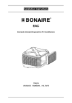
Figure 1 on page 2 shows a simple VSM configuration.
1
ExPR
TCP/IP
Control Path
VSM ESCON Control
& Data Path to VTDs
3270 Controller
Data Path to
Nearline trans
ports
VTDs
LMU
Nearline
transports
Figure 1. Simple VSM Configuration
2
RTDs
ESCON Data Path to
RTDs:
Migrate/Recall
Drain
Reclaim
Audit
VTVs
How Does VSM Work?
VTCS and HSC work together to provide several methods that you can use to route
data to VSM. Each VTSS provides 64 virtual tape drives (VTDs) for VSM2s and
VSM3s, and 256 VTDs for VSM4s. VTDs emulate 3490E devices. VSM uses the
VTDs to write data sets to virtual tape volumes (VTVs) on the VTSS. The VTSS
storage is provided by a RAID-6+ DASD configuration. You specify the VTSS’s
high and low Automatic Migration Thresholds (AMTs), which control the VTSS
space management/VTV migration cycle described on page 5. Real tape drives
(RTDs) write migrated VTVs to physical multi-volume cartridges (MVCs).
VSM2s and VSM3s support a maximum of 8 RTDs per VTSS, while VSM4s
support a maximum of 16 RTDs per VTSS. VTCS controls RTDs (although HSC
provides mount and dismount services for MVCs), while HSC controls
conventional Nearline tape drives that are not allocated to VSM. By default, VSM
migrates a single copy of a VTV. You can, however, used the MGMTclas MIGpol
parameter to specify that VSM migrates multiple copies of the VTV to separate
MVCs.
If the host requests a mount of a VTV that was migrated to an MVC and is not
VTSS–resident, VSM automatically recalls the migrated VTV to the VTSS.
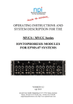
Figure 2 on page 4 shows the VTV migration/recall cycle.
Note: VSM supports dynamic sharing of RTDs between VTSSs. Note, however,
that when VTSSs share RTDs, the VTSSs must have access to all the same
hosts.
Also note that VSM does not support dynamic sharing of transports between VSM
and MVS. That is, a transport cannot simultaneously be online to both MVS and
to VSM as an RTD. You can, however, manually vary a transport online to MVS
and offline to VSM and vice versa.
3
Migration/Recall Cycle
Migration
Recall
Virtual Mount
data set written to VTV
VTSS
Virtual
Mount
Virtual Dismount,
VTV resident on VTSS
VTV recalled
to VTSS
VTV is collected
with other VTVs
Real Mount,
VTVs stacked on MVC,
Real Dismount
Real Mount for
recall of VTV
LSM
Figure 2.
VTV Migration/Recall Cycle
The following sections provide more information about VTV migration and recall,
MVC space reclamation, VTCS and NCS enhancements, VTV consolidation, an
overview of how to export and import data, and an overview of Clustered VTSS
configurations.
4
How VSM
Automatically
Manages VTSS
Space and Migrates
VTVs
VSM automatically manages VTSS space and migrates VTVs as follows:
1.
You route data sets to VSM.
2.
VTCS mounts a VTV on a VTD, writes the data set to the VTV, then
dismounts the VTV, which is now VTSS–resident.
3.
Disk Buffer Utilization (DBU) is the percentage of space used on a VTSS
compared to its capacity. VTCS starts automigrating VTVs once the DBU
reaches or exceeds the High Auto Migration Threshold (HAMT) or the
number of VTVs exceeds 97,000 (for VSM2s and VSM3s) or 291,000 (for
VSM4s). Automigration continues until the Low Auto Migration Threshold
(LAMT) is reached.
Note: VSM will initially start a number of automigration tasks according to
the workload characteristics within the limits of the MINMIG and MAXMIG
values. During the migration process, VTCS continuously adjusts the
number of tasks based on the DBU, the HAMT, and the migration target (the
LAMT or the migrate-to-threshold value).
VTCS selects VTVs for automigration in three modes, normal, high and
space release:
•
While the DBU is below or equal to the High Automatic Migration
Threshold (HAMT), VTCS operates in normal mode. In this mode,
VTCS selects VTVs for migration that are least likely to be rereferenced (based on VTV age) but also considers VTV size and any
recommendation for the residency time of each individual VTV
(RESTIME). VTCS migrates the selected VTVs and deletes the VTSSresident copies until DBU reaches the Low Automatic Migration
Threshold (LAMT).
•
If the DBU exceeds HAMT but is less than 95%, VTCS switches to high
mode. As DBU approaches 95%, VTCS progressively more heavily
weights VTV size versus age to select VTVs for migration. VTCS
continues to consider any RESTIME recommendations. VTCS migrates
the selected VTVs and deletes the VTSS-resident copies until DBU
reaches the LAMT.
•
If the DBU reaches 95%, VTCS switches to space release mode. In this
mode, any VTV that is resident but already migrated is first deleted from
the VTSS, after which VTCS only migrates VTVs on a size basis until
the LAMT is reached. VTCS does not honor any RESTIME
recommendations in space release mode.
Also note that when auto migrate selects candidate VTVs, all VTVs
associated with a multiple VTV group that spans a single data set are
included within the subsequent migration operation.
5
Demand Migrations
As an alternative to automatic migration, you can also use MIGRATE to do demand
migrations.
If you demand migrate specified VTVs, VTCS will start a single migration task.
A migrate-to-threshold triggers automigration for the specified VTSS and
temporarily sets the LAMT to the specified threshold value. The number of
migration tasks is determined as described in Step 3. on page 5.
You can also specify that VTCS immediately schedules VTVs for migration on
dismount. Just as with automatic migration and demand migrate-to-threshold,
immediate migration spawns one or more migration requests per VTSS within the
limits specified by the CONFIG VTSS MINMIG and MAXMIG parameters.
6
How VSM
Automatically
Recalls Migrated
VTVs
If the host requests a specific mount of a VTV whose most current copy is VTSS
resident, VSM mounts the VTSS resident copy of the VTV. Otherwise, VSM
automatically recalls the VTV as follows:
1.
For VTVs with multiple MVC copies managed by Advanced Management
Policies, VTCS selects the MVC to recall from as follows:
•
If one MVC is mounted, VTCS selects that MVC.
•
If neither MVC is mounted, VTCS selects the MVC from the first
Storage Class specified by the MIGpol parameter of the MGMTclas
statement. If the MVC in the first Storage Class is marked in error,
VTCS selects the MVC from the second Storage Class specified by the
MIGpol parameter.
2.
VTCS selects an RTD connected to the VTSS containing the VTD specified
in the mount request.
3.
VTCS directs HSC to mount the MVC on the selected RTD.
4.
VTCS recalls the entire VTV from the MVC.
5.
VTCS directs HSC to dismount the MVC (unless it is needed for another
VTV recall request).
6.
VTCS mounts the VTV on the VTD.
Note: If a host requests a mount of a data set that spans multiple VTVs,
when the mount is issued for any VTV referenced by the data set, VTCS also
recalls (if necessary) the next VTV in sequence. VTCS thus attempts to
“pre-stage” multiple VTVs referenced by the same data set.
7.
The host accesses the VTV. If the host changes the contents of the VTV,
VTCS marks the VTV space on the MVC as available for reclamation.
8.
At the end of the job, the host unloads the VTD.
Note: You can also use RECALL to do demand recalls.
Also note that by default, VTCS recalls VTVs with read data checks. For
example, if an MVC is defective, only part of a specific VTV may be readable, but
VTCS still recalls the readable portion, which creates a “partial” VTV in the
VTSS. If a VTV with read data checks contains critical data, you may choose to
recall just the readable portion, or you may choose to only recall complete VTVs.
7
How VSM
Automatically
Reclaims MVC
Space
VSM uses automatic space reclamation processing (which runs once an hour) to
reduce MVC fragmentation and increase available space. VSM reclaims space one
MVC at a time by copying only current VTVs from the selected MVC to the
VTSS, then copying these VTVs back to a second MVC. VSM copies only those
VTVs placed after the first open space on the MVC, which saves I/O cycles. In a
multi-VTSS environment, VTCS attempts to balance the recall and migration
tasks required for reclamation across all VTSSs. Note EXPORT marks exported
MVCs as readonly, so they are not candidates for space reclamation.
You can use RECLAIM to do demand reclamations.
8
Using the STORclas
MEDIA Parameter
for MVC Media
Preferencing
By default, in mixed-media VSM systems, VTV automatic and demand
migrations (and consolidations) go to MVCs by media type in this order:
1.
Standard length 3480 cartridge
2.
3490E cartridge
3.
3490EE cartridge
4.
T9840A/B cartridge
5.
T9840C cartridge
6.
T9940A cartridge
7.
T9840D cartridge
8.
T10000 sport cartridge
9.
T9940B cartridge
10. T10000 full capacity cartridge
By default, for automatic and demand space reclamations, VSM writes VTVs to
output MVCs by media type in this order:
1.
T10000 full capacity cartridge
2.
T9940B cartridge
3.
T10000 sport cartridge
4.
T9840D cartridge
5.
T9940A cartridge
6.
T9840C cartridge
7.
T9840A/B cartridge
8.
3490EE cartridge
9.
3490E cartridge
10. 10. Standard length 3480 cartridge
Note:
•
MVC pool has at least one media type compatible with each RTD type.
•
The MEDIA parameter of the STORclas statement (which defines Storage
Classes) specifies a preference list of MVC media types. This list supersedes
the default media selection list. For more information, see VTCS Command
and Utility Reference.
9
The MEDIA parameter of the STORclas statement (which defines Storage Classes)
specifies a preference list of MVC media types. This list supersedes the default
media selection list. Note that for reclamation, VTVs are written back to MVCs
in the reverse of the order specified on the MEDIA parameter.
•
For example, if you specify the following on the MEDIA parameter of the
STORclas statement...
MEDIA(STK1RAB,STK1RC,STK2PB)
10
•
...to select an MVC for migration to this Storage Class, VTCS searches
for a usable MVC in the order STK1RAB, STK1RC, STK2PB.
•
...to select an MVC for the output of reclaim to this Storage Class, VTCS
searches for a usable MVC in the order STK2PB, STK1RC, STK1RAB.
•
You can specify the media and ACS preferencing via the Storage Class(es)
specified on the MIGpol parameter of the MGMTclas control statement.
•
To optimize recall processing in mixed-media systems, ensure that your
MVC pool has at least one media type compatible with each RTD type.
How VSM Maintains
Data Integrity and
Availability When
Moving VTVs from
One MVC to Another
During a drain process (MVC drain or space reclamation), VTCS maintains data
integrity and availability by not altering the MVC reference in the VTV record
until that VTV has been recalled and successfully migrated to a new MVC. In
addition, VTCS immediately migrates VTVs recalled by a drain process instead of
allowing Automatic Migration to migrate the VTVs. If a drain operation does not
complete (is cancelled, the system fails, and so forth), you must rerun the drain
operation, but all in-transit VTVs will still point to the MVC that was being
drained. If a VTV is migrated to multiple MVCs and one MVC is in error, VTCS
recalls the VTV from an alternate MVC and immediately migrates the VTV
without waiting for subsequent processing of the in-error MVC.
Note that, for both MVC drains and space reclamations, VTCS does a
Management Class lookup after the recall phase and honors any Management
Class changes.
How VTCS Manages
Scratched VTVs
When a VTV is scratched, VTCS sets scratch status on in the VTV record in the
CDS. VTCS does not delete the VTV from the VTSS buffer. Instead, VTCS
unlinks all MVC copies except the last one. VTCS does not unlink the last MVC
copy until the VTV is reused as a scratch volume. If the VTV is simplexed, then
the single VTV copy is preserved until the VTV is reused as a scratch volume. If
there is more than one copy of the VTV (duplex, and so forth) then copies are
deleted as MVCs are reclaimed, until there is only one VTV copy left. VTCS
preserves this VTV copy until it is reused as a scratch volume.
11
VSM Basic and
Advanced
Management
Features
HSC provides the Basic Management Feature that enables the MGMTclas control
statement NAME, ACSlist, IMMEDmig, DUPlex, and DELSCR parameters.
The Advanced Management Feature, which is available as a chargeable feature,
enables the Basic Management Feature plus:
•
The STORclas control statement; for more information.
•
The MGMTclas control statement MIGpol, RESTIME, CONSRC, and CONTGT, and
REPLICAT parameters.
•
EXPORT and IMPORT.
The Advanced Management Feature, therefore, extends VSM Management Class
function and enables VSM Storage Classes as described in “VSM Management
and Storage Classes” on page 13. EXPORT and IMPORT let you create portable
MVCs to move data from one VSM system to another.
Using the Advanced Management Feature, you can:
12
•
Control media selection for migration, reclaim, and consolidation.
•
Select the location for consolidation input.
•
Specify preferred VTSS residency time for VTVs.
•
Group or segregate workloads on MVCs.
•
Quickly move data on VTVs and MVCs between VSM systems.
•
Create and manage Clustered VTSS configurations.
VSM Management
and Storage Classes
VSM Management and Storage Classes provide the following VTV management
capabilities:
•
VSM Management Classes specify how VTCS manages VTVs. The
MGMTclas control statement defines a VSM Management Class and its
attributes. For example, the DELSCR parameter of the MGMTclas statement
specifies whether VSM deletes scratched VTVs from the VTSS.
•
VSM Storage Classes specify where migrated VTVs reside. The HSC
STORclas control statement defines a VSM Storage Class and its attributes.
For example, the MEDIA parameter of the STORclas statement specifies a
preference list of MVC media types. To control the output MVC media and
ACS location for consolidation, for example, you can specify a Storage
Class with the desired attributes on the CONTGT parameter of the MGMTclas
statement.
For more information about VSM Management Features, see “VSM Basic and
Advanced Management Features” on page 12. For more information about the
VSM policies available through VSM Management and Storage Classes.
Note: You can use the VTVMAINT utility to change a VTV’s Management Class.
Also note that while you cannot use VTVMAINT to directly change a VTV's Storage
Class, you can use VTVMAINT to change a VTV's Management Class, which can
reference a different Storage Class.
The Import and
Export Functions
You can use EXPORT and IMPORT to move VTVs on MVCs from one VSM system
to another, where each system has its own unique resources, including different
CDSs. EXPORT and IMPORT, therefore, give you the ability to create portable MVCs
that you can use to move VTVs from one system to another. For more information,
see “Exporting and Importing VTVs” on page 53.
Note: For each VTV imported, the only MVC copies that will be created will be
for MVCs that have been exported and imported via the same statements. This has
a particular significance when importing Duplexed VTVs. Such a VTV will only
have copies on both MVCs after the import if both MVCs are present in the same
Manifest file and imported as a result of the same IMPORT statement.
13
Clustered VTSS
Configurations
Clustered VTSS configurations come in two types:
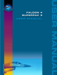
•
Uni-Directional Clusters, which consist of a Primary VTSS and a Secondary
VTSS connected by one or more cluster links (CLINKs). Figure 3 shows a
Uni-Directional Cluster attached to a single ACS. The CONFIG CLUSTER
statement defines the Cluster, and the CONFIG CLINK statement(s) define this
the Cluster as Uni-Directional.
In a Uni-Directional Cluster, you can use the MGMTclas statement REPLICAT
parameter (which requires the Advanced Management Feature) to direct the
Primary VTSS to replicate (copy) a VTV to the Secondary VTSS via a
cluster link (CLINK). If the Primary VTSS becomes unavailable, you can
use the VARY VTSS to vary it offline to VTCS. You then vary the Secondary
VTSS’s VTDs online to MVS to continue the workload. The Secondary,
therefore, acts as a “warm standby” to the Primary VTSS. Note that the
Secondary can accept production work as well as replicated VTVs.
Figure 3. Uni-Directional Cluster attached to a Single ACS
14
•
Bi-Directional Clusters, which consist of two Peer VTSSs connected by one
or more cluster links (CLINKs). Figure 4 shows a Bi-Directional Cluster
attached to a single ACS. The CONFIG CLUSTER statement defines the Cluster,
and the CONFIG CLINK statement(s) this Cluster as Bi-Directional.
In a Bi-Directional Cluster, you can use the MGMTclas statement REPLICAT
parameter (which requires the Advanced Management Feature) to allow
replication in either direction from peer to peer across a cluster link
(CLINK). If either VTSS becomes unavailable, you can use the VARY VTSS
to vary it offline to VTCS and the Peer VTSS takes over the workload. Each
Peer VTSS, therefore, acts as a “warm standby” to the other, and each can
accept production work as well as send and receive VTVs.
Figure 4 shows a Peer-to-Peer VTSS Cluster cross-connected to two ACSs for
increased redundancy (for example, for enhanced Disaster Recovery capability).
Figure 4. Bi-Directional Cluster attached to a Dual ACS
Compared to a non-clustered configuration, a Clustered VTSS configuration can
provide enhanced data availability (business continuance) and enhanced disaster
recovery capability (business resumption) for your VSM system.
For more information, see “Implementing a Clustered VTSS Configuration” on
page 59.
15
Near Continuous
Operations (NCO)
VTCS 6.1 provides Near Continuous Operations (NCO). Basically, NCO means
that you can now dynamically add, change, and delete hardware components,
VTVs, and MVCs without having to bring VTCS down and back up again. NCO
requires an “F” level CDS, which is enabled by specifying V61ABOVE on the
CDSLEVEL parameter of the CONFIG utility. After you have run CONFIG with V61ABOVE,
you can add, change, or delete RTDs and VTSSs while the devices are online and
the changes take affect immediately without having to recycle VTCS.
In general, however, and exclusive of NCO, consider the following when you are
deleting devices:
•
You do not need to empty a VTSS prior to deletion. What you do need to
ensure is that all VTVs are fully migrated. Also consider changing other
parameters, for example, TAPEREQ statements so that new work is not routed
to the removed VTSS.
•
If removing all of one device type/ACS combination from a VTSS, also
ensure that all VTVs are fully migrated first. As above, consider changing
other parameters to reflect the changed migration capabilities of the VTSS
(for example, Management Classes, which point to Storage Classes that
specify ACS and media).
•
Note that you may choose to make non-NCO changes at the same time you
are making NCO device changes...which makes these changes non-NCO as
well.
•
To summarize, NCO enables you to make a hardware configuration change
without restarting VTCS. NCO does not, however, eliminate the need for
planning the change and understanding its implications.
For more information about configuring VTCS 6.1, see VTCS Installation and
Configuration Guide. For more information about the VARY RTD and VARY VTSS
commands, see VTCS Command and Utility Reference.
16
How VSM Measures Sizes and Capacities
VTCS uses the binary standard rather than the decimal standard in displaying and
calculating sizes and capacities. Thus:
•
1 kilobyte=1024 bytes
•
1 megabyte=1024 kilobytes or 1024*1024 bytes
•
1 gigabyte=1024 megabytes or 1024*1024*1024 bytes
17
18
Chapter 2. Managing VSM
This chapter tells how to do the following VSM management tasks:
•
“Managing VTSSs and VTDs” on page 21
•
“Managing VTVs” on page 22
•
“Managing MVCs” on page 24
•
“Managing RTDs” on page 39
•
“Doing CDS Maintenance and Recovery” on page 42
•
“Expanding Your CDS” on page 46
•
“Doing Demand Migrations, Recalls, and Space Reclamations” on page 48
•
“Sharing Transports Between VSM and MVS” on page 49
•
“Exporting from a Source VSM System” on page 56
•
“Importing into a Target VSM System” on page 58
•
“Implementing a Clustered VTSS Configuration” on page 59
•
“Resolving Common VSM Problems” on page 87
“VSM Management Tools” on page 20 lists these tools and cross-references the
sections of this book that describe these tools.
Warning: The extended format CDS is required for VTCS 5.1.0 with VSM4s
configured with greater than 64 VTDs and/or greater than 16 RTDs. You must use
the HSC 5.0 or higher MERGEcds utility to convert the CDS to extended format.
Note that after you convert the CDS to extended format, you cannot run VTCS
4.0.0 or lower against the converted CDS. For more information, see “Converting
the Formatted CDS to Extended Format” in Chapter 5 of VTCS Installation and
Configuration Guide.
19
VSM Management Tools
VSM provides the following management tools:
•
MVC reports.
•
MVC pool summary reports.
•
VTV reports.
•
MVCMAINT and VTVMAINT.
•
Query.
•
VTCS messages; see Virtual Tape Control System Messages.
In addition, if you have ExPR installed, use ExPR reports to help manage your
system, and if you have ExLM installed, you can use it to help manage MVC
availability. You should also use your tape management system data set reports to
help manage VSM.
20
Managing VTSSs and VTDs
Use the following guidelines to manage your system’s VTSSs and VTDs:
•
Periodically review your VTSS management policies.
•
Monitor VTD status with Query VTD.
•
Monitor DBU and VTSS policies with Query, ExPR reports, and VSM
messages.
•
Monitor migration status with Query and, if necessary, use SET MIGOPT to
change AMTs or MINMIG or MAXMIG settings.
•
AMT settings are your primary tool for managing VTSS space and VTV
migration.
•
Consider the effect a policy has on VTSS space. For example, setting
IMMEDmig DELETE on the MGMTclas statement ensures that VSM quickly
migrates jobs in that class to MVCs and conserves VTSS space. Note,
however, that immediately migrating VTVs uses MVC space more rapidly.
•
Consider doing demand migrations to supplement automatic migration; for
more information, see “Doing Demand VTV Migrations” on page 48.
•
Ensure that you maintain sufficient free MVCs and usable MVC space; for
more information, see “Managing MVCs” on page 24.
•
Ensure that you have sufficient RTDs available, for more information, see
“Sharing Transports Between VSM and MVS” on page 49.
•
If you physically remove a VTSS from your configuration, rerun CONFIG.
Note: Before you remove the VTSS, ensure that you migrate and delete all
copies of VTVs from that VTSS so these VTVs can be recalled to a different
VTSS in your system.
•
If a VTSS fails or you want to take it offline for service, you can recall VTVs
migrated from the failed VTSS to an alternate VTSS.
21
Managing VTVs
Use the following guidelines to manage your system’s VTVs:
•
Periodically review your VTV management policies.
Note: You can use the VTVMAINT utility to change a VTV’s Management
Class.
•
Ensure that you have sufficient VTVs. Use Query and VTV reports to
monitor VTV status.
If you need more VTVs, do one of the following:
•
Free VTV volsers by scratching VTVs with data that is not current.
•
Change your TAPEREQ statements or SMS routines to temporarily reroute
tape work to Nearline HSC processing until you can define additional
VTVs.
•
Use CONFIG to add VTVs.
VTVs require additional definitions besides the CONFIG VTVVOL statement.
•
22
Manage VTV scratch status:
•
If you use scratch subpools for VTVs, manage them as described in the
guidelines in VTCS Installation and Configuration Guide.
•
Use Query, VTV reports, and tape management system reports to
monitor VTV scratch status.
•
Use the HSC scratch utilities or the ExLM SYNCVTV function to scratch
VTVs with data that is not current.
•
Use CONFIG to add scratch VTVs.
•
Use the HSC Operator commands to manage VTVs.
•
Manage VTV accessibility by ensuring that VTVs that are frequently
referenced are VTSS-resident:
•
Review your migration policies, especially the settings for the following
parameters:
• The DELSCR parameter of the MGMTclas statement.
• The RESTIME parameter of the MGMTclas statement.
• The IMMEDmig parameter on the MGMTclas statement.
•
If these VTVs are not VTSS-resident, consider doing demand recalls
before the data is needed; for more information, see “Doing Demand
VTV Recalls” on page 48.
Hint: VSM supports host based tape stacking methodologies, which you do not
have to disable to use VSM. However, because VSM provides a volume stacking
solution, StorageTek does not recommend that you implement a stacking
methodology with VSM if you are not already using a stacking methodology.
23
Managing MVCs
Use the following guidelines to manage your system’s MVCs:
•
Periodically review your MVC space reclamation policies.
•
Ensure that you have sufficient free MVCs and sufficient usable space on
MVCs that contain some VTVs. Use Query and MVC reports to monitor
MVC status.
Note: MVCs that contain VTVs that have a Storage Class cannot be used
for migration of VTVs in other Storage Classes. In addition, some free
MVCs can be limited to specific Storage Classes based on the MVC ACS
location or media type. Use the MVC report to manage these restrictions.
Running out of free MVCs and/or usable MVC space can cause any of the
following:
•
Migrates fail. As soon as MVC space becomes available, automatic
migration will restart, but you must restart any failed manual migrations.
•
Unexpected automatic MVC space reclamation starts, which ties up
RTDs and slows VTV migration and recall response time.
•
Intervention is required on all output VTDs if a VTSS’s DBU reaches
100% DBU. If this occurs, you must add or make available more MVCs.
If you need more free MVCs or usable MVC space, do one or more of the
following:
•
24
•
Review your current policies and adjust as needed. You may be able to
create free MVCs or free space on MVCs by changing these policies.
•
Free VTV volsers by scratching VTVs with data that is not current,
which marks MVC space for reclamation.
•
Consider doing demand reclamation to free space; for more information,
see “Doing Demand MVC Space Reclamations” on page 48.
•
If necessary, add MVCs as described in “Adding MVCs to the MVC
Pool” on page 34.
If you have ExLM installed, ensure that ExLM does not move or eject your
MVCs or update their HSC scratch status; for more information, see “Using
ExLM with VTCS (All Versions)” in Chapter 2, “Using ExLM to Manage
Nearline and VTCS Resources” of ExLM System Administrator’s Guide.
Note that you can use ExLM LSM groupings to move MVCs into LSMs
with RTDs attached.
•
Compare the volsers on the MVC Summary Report to an HSC Volume
Report. Are the MVCs actually in the ACS? If not, you must either reenter
or replace any MVCs not listed on the HSC Volume Report. For more
information about the Volume Report utility, see Chapter 5, “Utility
Functions” of the HSC System Programmer’s Guide for MVS.
•
The MVC report, MVC Pool Report, and Query MVC report MVC statuses.
The following list shows these statuses (per Query MVC output) and tells how
to resolve problems:
BROKEN
This is a generic error that indicates the MVC, drive, or combination
of the two has a problem. VTCS attempts to de-preference MVCs with
this state. In general, to clear this state:
• If the MVC caused the problem, use a DRAIN(EJECT)
command to remove the MVC from service.
• If the RTD caused the problem, use the MVCMAINT utility to
reset the MVC state.
Note also that one or more of the following messages is issued for
BROKEN status: SLS6686, SLS6687, SLS6688, SLS6690. For detailed
recovery procedures for these messages, see VTCS Messages and
Codes.
DATA CHECK
A data check condition has been reported against this MVC. VTCS
attempts to de-preference MVCs with this state. To clear this state:
• If all VTVs on the MVC are duplexed, use MVCDRain on the
MVC without the Eject option. This recovers all VTVs and
removes the MVC from service.
• If all VTVs on the MVC are not duplexed, VTCS AUDIT the
MVC. The audit will probably fail. After the audit, do an
MVCDRAIN (no eject). This recalls the VTVs before the datacheck area in ascending block-id order and the VTVs after the
data-check area in a descending block-id order. Processing
the VTVs in this sequence ensures that VTCS recovers as
many VTVs as possible from the media. You then need to
recreate the data for any VTVs still on the MVC.
After clearing data checks, remove and replace MVCs with data
check errors as described in “Permanently Removing MVCs” on
page 35. This procedure also tells how to remove an MVC from
VTCS use and return it to Nearline operations.
DRAINING
The MVC is either currently being drained or has been the subject of a
failed MVCDRain.
IN ERROR
An error occurred while the MVC was mounted.
25
INITIALIZED
the MVC has been initialized.
LOST - FAILED TO MOUNT
VTCS attempted to mount an MVC and the mount did not complete
within a 15-minute time-out period. VTCS is attempting to recover
from a situation that may be caused by hardware problems, HSC
problems, or by the MVC being removed from the ACS. VTCS
attempts to de-preference MVCs with this state.
If VTCS does perform a subsequent successful mount of an MVC with
LOST(ON) state, VTCS sets the state to LOST(OFF).
Determine the cause of the error and fix it. You can also use the VTCS
MVCMAINT utility to set LOST(OFF) for the following events:
• LOST(ON) was set due to LSM failures or drive errors that have
been resolved
• LOST(ON) was set because the MVC was outside the ACS and
has been reentered.
MARKED FULL
The MVC is full and is not a candidate for future migrations.
MOUNTED
The MVC is mounted on an RTD.
NOT-INITIALIZED
The MVC has been defined via the CONFIG utility, but has not ever been
used.
READ ONLY
The MVC has been marked read-only because of one of the following
conditions:
• The MVC being the target of an export or consolidation process. The
read-only state protects the MVC from further updates.
• The MVC media is set to file protect. Correct the error and use the
MVCMAINT utility to set READONLY(OFF).
• The MVC does not having the appropriate SAF rules set to enable
VTCS to update the MVC. Correct the error (for more information,
see “Defining A Security System User ID for HSC, SMC, and
VTCS” in VTCS Installation and Configuration Guide) and use the
MVCMAINT utility to set READONLY(OFF).
BEING AUDITED
The MVC is either currently being audited or has been the subject of a
failed audit. If the audit failed, VTCS will not use the MVC for
migration. To clear this condition, rerun the AUDIT utility against this
MVC.
LOGICALLY EJECTED
26
The MVC has either been the subject of an MVCDRain Eject or the
MVC was ejected for update by a RACROUTE call. The MVC will not be
used again for migration or recall. To clear this condition, use MVCDRain
against the MVC without the Eject option.
RETIRED
The MVC is retired. VTCS will recall from, but not migrate to, the
MVC. Replace the MVC as soon as possible.
WARRANTY HAS EXPIRED
The MVC’s warranty has expired. VTCS continues to use the MVC.
You should start making plans to replace the MVC when it reaches
Retired state.
INVALID MIR
VTCS has received status from an RTD to indicate the MIR (media
information record) for a 9x40 media is invalid. An invalid MIR does
not prevent access to data but may cause significant performance
problems while accessing records on the tape. The MVC is not capable
of high-speed searches on areas of the tape that do not have a valid
MIR entry.
VTCS attempts to de-preference MVCs with this condition. For
recalls, if the VTV resides on multiple MVCs, VTCS selects MVCs
with valid MIRs ahead of MVCs with invalid MIRs. VTCS avoids
using MVCs with invalid MIRs for migration, unless the migration is
at the beginning of the tape. Migrating from the beginning of tape will
correct the MIR.
VTCS detects the invalid MIR condition at either mount time or
dismount time. If detected at mount time and the operation can be
completed with another MVC, VTCS dismounts the first MVC and
selects the alternate MVC. Note that VTCS has only a limited ability
to switch to an alternate MVC. That is, it is mainly used for migrate and
virtual mount.
For MVCs with invalid MIRs, determine the cause of the error, which
may be caused by media or drive problems, and fix the error.
To recover an MVC with an invalid MIR, you simply need to read the
MVC to the end of the tape, which can be done via a VTCS audit. If
the media is the problem, run an MVCDRAIN EJECT to recall the VTVs
and cause the MVC to be removed from the MVC pool.
27
Converting MVCs
from T9840A/B
Media to T9840C
Media
The following sections tell how to convert your MVCs from T9840A or T9840B
media to T9840C media.
NCS/VTCS Support
for T9840C
The T9840C transport and media is supported as an RTD by the following releases
of NCS/VTCS:
•
VTCS/NCS 6.1 and 6.2 base
•
VTCS/NCS 6.0 plus PTF L1H11TP
•
VTCS/NCS 5.1 with the following PTFs installed:
•
•
L1H11o5 for VTCS 5.1
•
L1H11To for VTCS 5.1
•
L1H11o6 for HSC 5.1
VTCS/NCS 5.0 with the following PTFs installed:
•
L1H11PX for VTCS 5.0
•
L1H11TN for VTCS 5.0
•
L1H11PW for HSC 5.0
•
T9840C support is available only for VSM3s and VSM4, not for VSM2s.
•
“Changing RTD Device Types” on page 40 describes how to change RTD
device types. Follow this procedure to convert one or more RTDs from
T9840A/B devices to T9840C devices.
•
“Adding MVCs to the MVC Pool” on page 34 describes how to add
additional MVC media to your MVCPool. Follow this procedure if
additional media is required to support the T9840A/B to T9840C
conversion.
•
T9840A/T9840B and T9840C transports use the same physical form factor
but different recording techniques resulting in the following restrictions:
•
T9840Cs can read from media written to by T9840As/T9840Bs, but
cannot write to T9840A/T9840B media unless the entire volume is
rewritten from beginning of tape.
•
T9840As and T9840Bs cannot read from or write to media written to by
T9840Cs.
•
Use one of the following procedures to change your MVCs to T9840C
media:
• “Converting All T98400A MVCs to T9840C Media” on page 29
• “Using a Mixture of T9840A/B and T9840C Media” on page 30
28
Converting All
T98400A MVCs to
T9840C Media
To convert all T98400A MVCs to T9840C media:
1.
Change the device types of the RTDs from T9840A/B to T9840C.
For more information, see “Changing RTD Device Types” on page 40.
Note: You may want to retain one or more T9840A device types per VTSS
until the media conversion is complete.
2.
Modify the HSC VOLLATTR statements for all T9840A/B MVCs and
define them as T9840C media.
Warning: T9840C media require RECTECH(STK1RC) in addition to
MEDIA(STK1R)!
For example:
VOLATTR SERIAL(MVC900-MVC999) MEDIA(STK1R) RECTECH(STK1RC).
3.
Review the Storage Class definitions and change all references from
STK1R to STK1RC.
VTCS records the media type of all MVCs. Therefore all pre-existing MVCs
with data on them will remain known to VTCS as T9840A/B media. No
further migrates will occur from T9840C drives to these MVCs with preexisting data.
4.
Start HSC/VTCS with the new definitions...
...to run VOLDEF against the updated VOLATTRs, and so forth.
All migrates will now be to T9840C media. The data that resides on
T9840A/B media will eventually expire and these MVCs will become
reclaim candidates. If an MVC that is written in STK1R format and has a
VOLLATTR specifying RECTECH(STK1RC) is reclaimed then the MVC will be
completely drained and will therefore become a candidate for STK1RC
migration. Thus over a period of time all STK1R media will naturally be
converted to STK1RC media. This process can be accelerated by using
MVCDRAIN to drain STK1R media.Once all STK1R media is converted to STK1RC
media then any remaining T9840A/B drives can be removed.
29
Using a Mixture of
T9840A/B and
T9840C Media
If you want to use 9840A/B and 9840C media concurrently, to ensure media
and transport compatibility, you must use separate VOLATTR statements to
segregate 9840A/B and 9840C media as follows:
•
If you have existing 9840A/B media, these volumes are already
defined with the VOLATTR MEDIA parameter value of STK1 or STK1R. If you
are adding T9840C media, you must change your existing 9840A/B
VOLATTR statements to specify MEDIA(STK1R) and RECHTECH(STK1RAB).
You also need to define your new 9840C media with VOLATTR statements
that specify MEDIA(STK1R) and RECTECH(STK1RC).
For example, to define MVCs MVC900-MVC999 as 9840C media and to
redefine MVCs MVC600-MVC899 as 9840A/B media, you need the
following VOLATTR statements:
VOLATTR SERIAL(MVC900-MVC999) MEDIA(STK1R) RECTECH(STK1RC)
VOLATTR SERIAL(MVC600-MVC899) MEDIA(STK1R) RECTECH(STK1RAB)
•
If you are adding both 9840A/B and 9840C media, you must create
separate VOLATTR statements to segregate the media as follows:
• Define the 9840A/B media with VOLATTR statements that specify
MEDIA(STK1R)and RECTECH(STK1RAB).
• Define the 9840C volumes with VOLATTR statements that specify
MEDIA(STK1R)and RECTECH(STK1RC).
For example, to define MVCs MVC600-MVC899 as 9840A/B media and
MVCs MVC900-MVC999 as 9840C media, create the following VOLATTR
statements:
VOLATTR SERIAL(MVC600-MVC899) MEDIA(STK1R) RECTECH(STK1RAB)
VOLATTR SERIAL(MVC900-MVC999) MEDIA(STK1R) RECTECH(STK1RC)
Review your Management Class and Storage Class definitions to ensure that
data is directed to the desired MVC media type.
30
Converting MVCs
from T9940A Media
to T9940B Media
The following sections tell how to convert your MVCs from T9940A media to
T9940B media.
NCS/VTCS Support
for T9940B
The T9940B transport and media is supported as an RTD by the following releases
of NCS/VTCS:
•
VTCS/NCS 6.1 and 6.2 base
•
VTCS/NCS 6.0 plus PTF L1H11TP
•
VTCS/NCS 5.1 with the following PTFs installed:
•
•
L1H11o5 for VTCS 5.1
•
L1H11To for VTCS 5.1
•
L1H11o6 for HSC 5.1
VTCS/NCS 5.0 with the following PTFs installed:
•
L1H11PX for VTCS 5.0
•
L1H11TN for VTCS 5.0
•
L1H11PW for HSC 5.0
•
T9940B support is available only for VSM3s and VSM4, not for VSM2s.
•
“Changing RTD Device Types” on page 40 describes how to change RTD
device types. Follow this procedure to convert one or more RTDs from
T9940A devices to T9940B devices.
•
“Adding MVCs to the MVC Pool” on page 34 describes how to add
additional MVC media to your MVCPool. Follow this procedure if
additional media is required to support the T9940A to T9940B conversion.
•
T9940A and T9940B transports use the same physical form factor but
different recording techniques resulting in the following restrictions:
•
T9940Bs can read from media written to by T9940As, but cannot write
to T9940A media unless the entire volume is rewritten from beginning
of tape.
•
T9940As cannot read from or write to media written to by T9940Bs.
•
Use one of the following procedures to change your MVCs to T9940B
media:
• “Converting All T98400A MVCs to T9840C Media” on page 29
• “Using a Mixture of T9840A/B and T9840C Media” on page 30
31
Converting All
T9940A MVCs to
T9940B Media
To convert all T9940A MVCs to T9940B media:
1.
Change the device types of the RTDs from T9940A to T9940B.
For more information, see “Changing RTD Device Types” on page 40.
Note: You may want to retain one or more T9940A device types per VTSS
until the media conversion is complete.
2.
Modify the HSC VOLLATTR statements for all T9940A MVCs and define
them as T9940B media.
Warning: T9940B media require RECTECH(STK2PB) in addition to
MEDIA(STK2P)!
For example:
VOLATTR SERIAL(MVC900-MVC999) MEDIA(STK2P) RECTECH(STK2PB).
3.
Review the Storage Class definitions and change all references from
STK2P to STK2PB.
VTCS records the media type of all MVCs. Therefore all pre-existing MVCs
with data on them will remain known to VTCS as T9940A media. No further
migrates will occur from T9940B drives to these MVCs with pre-existing
data.
4.
Start HSC/VTCS with the new definitions...
...to run VOLDEF against the updated VOLATTRs, and so forth.
All migrates will now be to T9940B media. The data that resides on T9940A
media will eventually expire and these MVCs will become reclaim
candidates. If an MVC that is written in STK2P format and has a VOLLATTR
specifying RECTECH(STK2PB) is reclaimed then the MVC will be completely
drained and will therefore become a candidate for STK2PB migration. Thus
over a period of time all STK2P media will naturally be converted to STK2PB
media. This process can be accelerated by using MVCDRAIN to drain STK2P
media.Once all STK2P media is converted to STK2PB media then any
remaining T9940A drives can be removed.
32
Using a Mixture of
T9940A and T9940B
Media
If you want to use media concurrently, to ensure media and transport
compatibility, you must use separate VOLATTR statements to segregate
T9940A and T9940B media as follows:
•
If you have existing T9940A media, these volumes are already defined
with the VOLATTR MEDIA parameter value of STK2P. If you are adding
T9940B media, you must change your existing T9940A VOLATTR
statements to specify MEDIA(STK2P) and RECHTECH(STK2PA). You also
need to define your new T9940B media with VOLATTR statements that
specify MEDIA(STK2P) and RECTECH(STK2PB).
For example, to define MVCs MVC900-MVC999 as T9940B media and to
redefine MVCs MVC600-MVC899 as T9940A media, you need the
following VOLATTR statements:
VOLATTR SERIAL(MVC900-MVC999) MEDIA(STK2P) RECTECH(STK2PB)
VOLATTR SERIAL(MVC600-MVC899) MEDIA(STK2P) RECTECH(STK2PA)
•
If you are adding both and T9940B media, you must create separate
VOLATTR statements to segregate the media as follows:
• Define the T9940A media with VOLATTR statements that specify
MEDIA(STK2P)and RECTECH(STK2PA).
• Define the T9940B volumes with VOLATTR statements that specify
MEDIA(STK2P)and RECTECH(STK2PB).
For example, to define MVCs MVC600-MVC899 as T9940A media and
MVCs MVC900-MVC999 as T9940B media, create the following VOLATTR
statements:
VOLATTR SERIAL(MVC600-MVC899) MEDIA(STK2P) RECTECH(STK2PA)
VOLATTR SERIAL(MVC900-MVC999) MEDIA(STK2P) RECTECH(STK2PB)
Review your Management Class and Storage Class definitions to ensure that
data is directed to the desired MVC media type.
33
Adding MVCs to the
MVC Pool
You can often create free MVCs or free MVC space as described in “Managing
MVCs” on page 24. You may still, however, occasionally need to add MVCs to
your MVC pool to increase the available MVC space.
If you have defined MVCs via CONFIG that you are not using because they are not
defined on your MVCPool statements, update your MVCPool statements to expand the
range of in-use MVCs as shown in the following procedure. Otherwise, rerun
CONFIG to define new MVC ranges, then do the procedure below.
Note: If you must rerun CONFIG to define new MVC ranges, you must restart
VTCS/HSC after you rerun CONFIG.
To add MVCs to the MVC pool by updating your MVCPool statements:
1.
Edit the data set that contains your system’s MVCPool statements.
2.
Add MVCPool statements for the new MVCs (or update your existing
MVCPool statements) and save the data set.
3.
Run the VT MVCDEF command on all hosts to activate the updated data
set.
Note: MVCs require additional definitions besides the MVCPool statements.
34
Removing MVCs
from the Pool
Permanently
Removing MVCs
To permanently remove MVCs from the pool, do the following:
1.
Edit the data set that contains your system’s MVCPool statements.
2.
Delete the MVCPool statements for the MVCs you want to remove and
save the data set.
3.
Run the VT MVCDEF command on all hosts to activate the updated data
set.
4.
Enter MVCDRain to drain the MVCs.
5.
If the MVCs are no longer required in an ACS, use an HSC Eject
command to eject the MVCs from the ACS.
For more information, see HSC/MVS Operator’s Guide.
6.
Remove the Nearline definitions, security restrictions, and tape
management system restrictions you defined for the MVC.
7.
If you want to reuse the tape volser for Nearline (non-VTCS) usage, do
one of the following:
a. Change the external bar code label on the cartridge.
You must change the external bar code label, because the original MVC
volsers are retained in the CDS, and these volsers are only available for
use as MVCs.
b. Reenter the cartridge into the ACS.
OR
a. Create a new set of CDS data sets.
b. Modify VTCS CONFIG to remove the definition of the volser as an MVC.
c. Use HSC CDSMERGE to copy the original CDS to the new CDS.
d. Reenter the volser into the library.
35
Temporarily
Removing MVCs
To temporarily remove MVCs from the pool:
1.
Enter MVCDRain Eject for the MVC.
This does the following:
2.
•
Recalls all VTVs on the MVC and remigrates them to new MVCs.
•
Makes the MVC non-selectable for VTCS migrates.
To return the MVC to the MVC pool, enter a MVCDRain for the MVC.
Entering MVCDRain without the EJect parameter for the MVC makes it
available again.
Note: As an alternative, you can use MVCMAINT to mark an MVC as readonly. This
prevents VTCS from selecting the MVC for migrates but does not remove the
VTVs from the MVC. You can also use MVCMAINT to turn off the readonly
condition.
36
Resolving MVC Data
Checks
To resolve MVC Data Checks:
1.
If all VTVs on the MVC are duplexed, run an MVCDRain (no eject) on
the MVC.
The MVCDrain:
•
Causes all the available VTVs to be recalled to a VTSS and then
remigrated to a new error-free MVC.
•
Logically removes the MVC from the MVC pool.
If all VTVs on the MVC are not duplexed, continue with Step 2. Otherwise,
go to Step 5.
2.
If all VTVs on the MVC are not duplexed, run an MVC audit against
the MVC.
The audit attempts to read the VTV metadata sequentially from the MVC.
The audit fails when it encounters the data check, which leaves the MVC in
an auditing state. This prevents VTCS from selecting this MVC for output.
3.
After the audit, do an MVCDRAIN (no eject).
The MVCDrain recalls the VTVs before the data-check area in ascending
block-id order and the VTVs after the data-check area in a descending
blockid order. Processing the VTVs in this sequence ensures that VTCS
recovers as many VTVs as possible from the media.
4.
Determine if any VTVs could not be recovered from the MVC.
Run an MVC Detail report for the MVC. If any VTVs are still reported as
being on the MVC, then these VTVs are not recoverable and were not
duplexed; you must recreate your data.
5.
Manage the defective MVC by doing one of the following:
•
Replace the defective MVC with an initialized tape volume with the same
internal and external labels:
1.
HSC EJECT the defective MVC.
2.
HSC ENTER the replacement MVC.
3.
Initialize the tape as required.
4.
HSC AUDIT the new MVC.
•
Run an MVCDRAIN (no EJECT) to return the MVC to the MVC pool.
Remove the MVC from the system as described in “Permanently Removing
MVCs” on page 35.
37
Moving MVCs
Between ACSs
In multi-ACS VSM configurations, especially where you have different VTSS
connections to each ACS, you can move MVCs from one ACS to another to make
more MVC space available to one or more VTSSs.
To move MVCs from one ACS to another:
1.
Eject the MVCs from the first ACS, then enter them into the second
ACS.
For more information, see HSC/MVS Operator’s Guide.
2.
Ejecting MVCs
Enter the VT MVCDEF command to reload the MVCPool statements.
If you eject MVCs, you must reload the MVCPool statements with a VT MVCDEF
command.
To eject MVC:
1.
Eject the MVCs.
For more information, see HSC/MVS Operator’s Guide.
2.
Enter the VT MVCDEF command to reload the MVCPool statements.
The ejected MVCs will now show as not in the ACS on an MVC report or Q
MVC command.
Managing MVCs in
LSM Manual Mode
Managing MVCs when the LSM is in manual mode is just like managing any
Nearline volume in this situation. For more information, see “LSM Manual Mode
Procedures” in Chapter 3, “Operating an Automated Cartridge System” of HSC
Operator’s Guide for MVS. In manual mode, the transport display panel
alternately displays the volser and cell location of the requested volume for both
RTDs and Nearline transports that are not RTDs.
In automatic mode, the transport display panel alternately displays the volser and
cell location of the requested volume for RTDs, but displays only the volser for
Nearline transports that are not RTDs.
38
Managing RTDs
Use the following guidelines to manage your system’s RTDs:
•
If VTCS detects a read/write error on an MVC, VTCS will swap the MVC
to another RTD to verify the MVC media. StorageTek recommends,
therefore, that for each MVC media type you have at least two compatible
RTDs available at all times. You can use the Query RTD to check RTD
availability, Query TASKs to monitor tasks associated with RTDs, and Cancel
to cancel processes that use RTDs. Note that, depending on your
configuration, RTDs may be available to multiple hosts, so you need to
check RTD availability for each host.
Caution: If you cancel a task associated with migration scheduler (either
with the MIGrate parameter or by specific process ID), this task will
terminate but migration scheduler will start another migration task at its next
timer interval. You can, however, use migrate-to-threshold to stop
automigration by specifying a value greater than the current DBU.
•
Note that VTCS balances requests that require RTDs by giving each request
a variable time to complete; if the request does not complete in this time,
VTCS allocates the RTD to another queued request. If, therefore, many
requests are queued for RTDs, all requests can take longer to process
because VTCS is mounting, dismounting, and repositioning MVCs instead
of reading from or writing to them. The short term solution, as above, is to
use Query RTD to check RTD availability, Query TASKs to monitor tasks
associated with RTDs, and Cancel to cancel processes that use RTDs. The
long term solution is to review your VSM policies, all of which affect RTD
use.
•
See “Changing RTD Device Types” on page 40 for more information about
changing your system’s RTDs from one transport type to another.
•
See “Defining Manual RTDs” on page 41 if you need to do this in a DR
situation.
•
Also see “Resolving Common VSM Problems” on page 87, which tells how
to resolve common problems involving RTDs.
39
Changing RTD
Device Types
Use the following procedure to change RTD device types. Note that changing
RTD device types requires you to stop VTCS on all hosts.
To change RTD device types, do the following:
1.
Review your VSM policies.
For example, you may want to review your Management Class and Storage
Class definitions if this RTD device type is used for migrations.
2.
Vary the old RTDs offline to VTCS.
3.
If the new RTD devices use new MVS device addresses, do the
following:
•
Define the new addresses to MVS.
•
Run DECOM to output your CONFIG statements.
•
Edit the CONFIG statements to change the RTD addresses to the new
values.
•
Run CONFIG RESET.
Caution: Do not vary the new transports online to MVS! Otherwise, they
can be allocated as Nearline transports.
4.
Install the new RTDs.
5.
Vary the LSM(s) where transports were replaced to offline status.
6.
Vary the LSM(s) where transports were replaced to online status.
7.
Vary the VTSS where RTDs were replaced to offline status.
8.
Vary the VTSS where RTDs were replaced to online status.
Because the VTSS was offline, VTCS reports that an audit of the VTSS is
now required. At a convenient time, audit the VTSS.
9.
Vary the new RTDs online to VTCS.
10. If necessary, add MVCs.
For more information, see “Adding MVCs to the MVC Pool” on page 34.
40
Defining Manual
RTDs
In a DR situation, you may have no automated tape resources available. To support
nonlibrary VSM configurations, you must define manual RTDs in a nonexistent
ACS.
To define manual RTDs:
1.
Generate LIBGEN macros to define a nonexistent ACS.
The SLIDRIVS macro defines the device address for the manual RTDs.
Note: The LSM in the nonexistent ACS can be defined as an SL8500 or
SL3000 to take advantage of the MODIFY CONFIG command.
2.
Run the SLICREAT utility to format a new CDS.
3.
Run SET SLIDRIVS utility to set the MODEL for the manual RTDs,
for example:
SET SLIDRIVS(400,401,402,403) MODEL(T9840C)
Note: Manual RTDs on the same panel must be the same drive type.
4.
Run the VTCS CONFIG utility to define the VSM system.
5.
Use the VTCS IMPORT utility to import MVCs into the new CDS to use
with the manual RTDs.
These MVCs are treated as nonlibrary volumes.
41
Doing CDS Maintenance and Recovery
StorageTek recommends the following guidelines for CDS maintenance and
recovery in a VSM system:
•
Ensure that the CDS is backed up at least daily, and more often if possible
(VTV and MVC changes typically occur throughout the day and cause CDS
changes).
If you lose the primary CDS and are recovering from a backup copy, make
sure to use the most recent copy.
A VTCS audit is not a substitute for frequent backup of the CDS. A VTCS
audit will regain access to your VSM resources, but in general it will not
completely reconstruct the VSM records in a CDS. For example, if you
delete all copies of the CDS, an audit will not recreate any Management
Class definitions. Therefore, StorageTek strongly recommends that you do
not delete all copies of the CDS, then run a VTCS audit!
•
If you have lost all copies of the CDS, use the procedure described in
“Recovering from Losing All Copies of the CDS” on page 44.
•
If the primary CDS is intact but you lost information about some VSM
resources, use the procedure described in “Recovering from Losing
Information about Some VSM Resources” on page 45.
For example, you would use this procedure if VTCS and HSC abended
while applications were writing VTVs to the VTSS and VTCS was doing
migrate, recall, and/or reclaim operations. In this situation, VTV and MVC
reports can help identify the lost information.
You would also use this procedure if the VTSS lost power. In this situation,
the SYSLOG can help identify any MVCs mounted at the time of the power
outage.
42
•
A VSM audit of all MVCs will audit MVCs defined with CONFIG MVCVOL
statements even if they are not specified in the MVCPool statements. If these
volumes are not in an ACS that VTCS accesses, HSC issues message
SLS2126I to prompt the operator to enter these volumes. If the volume does
not exist or is not available, the operator should reply “I” (ignore). If the
operator does not reply to this message, VTCS times out with this MVC after
20 minutes and continues with the next MVC.
•
Note that VSM does not support copies of the CDS at multiple sites (for
example, Primary CDS at one site and Secondary at another). A link failure
would allow the two sites to run independently, and VSM cannot enforce
separation of all resources. This prevents reconciliation of the two divergent
CDSs as can be accomplished in a pure NCS environment.
•
If you audit an export MVC, VTCS processes the VTVs on the MVC as
follows:
•
VTVs have an MVC1 and MVC2 field in the CDS. If the VTV’s time
and date stamp matches the CDS and the MVC1 and MVC2 fields are
empty (the VTV has not been migrated), VTCS marks the audited VTV
as current, fills in the empty MVC1 or MVC2 field, marks the MVC as
read-only and as a consolidation MVC, and issues warning messages.
•
If the VTV’s time and data stamp matches the CDS and the MVC1 and
MVC2 fields are filled in, VTCS ignores this VTV copy. If all VTVs on
the MVC are in this state, VTCS marks the MVC as empty and readonly, and issues warning messages.
•
If the VTV’s time and date stamp does not match the CDS, VTCS
ignores this VTV copy.
•
When HSC and VSM audits complete, run the HSC scratch conversion
utility (SLUCONDB) or the ExLM SYNCVTV function. Also ensure that the CDS
is backed up at this point.
•
Do not use VTVs to back up the CDS!
43
Recovering from
Losing All Copies of
the CDS
Use the following procedure to recover a VSM system after losing all copies of the
CDS.
To recover after losing all copies of the HSC CDS and update the MVC and
VTV information, do the following:
1.
To recover the HSC CDS, audit the library.
For more information about the HSC AUDIT utility, see Chapter 5, “Utility
Functions” in the HSC System Programmer’s Guide for MVS.
2.
Update your system’s MVC pool definition to load a null MVC pool.
A null MVC pool prevents migrations, consolidations, recalls, and space
reclamations, which ensures that MVCs are not overwritten during the audit.
3.
Prevent applications from writing data to or reading data from existing
VTVs during the audits.
Applications can write new VTVs to the VTSSs if the TMS is correct and
sufficient VTSS space exists.
4.
To update the recovered CDS with your VSM system’s MVC and VTV
information, do a full VSM audit.
When VTCS encounters VTVs with the same volsers, VTCS determines
which volume is the most current and uses that VTV. VTCS marks not
current the other copies of the VTV.
5.
Update the scratch status of your VSM system’s MVCs and VTVs.
After the VTCS audit, VTCS assumes that all VTVs are non-scratch. After
the VTCS audit completes, run the HSC scratch conversion utility or the
ExLM SYNCVTV function.
6.
44
Rerun any consolidation jobs that may have been impacted by the loss
of the CDS.
Recovering from
Losing Information
about Some VSM
Resources
Use the following procedure to recover after losing information about some VSM
resources.
To recover after losing information about some VSM resources, do the
following:
1.
If necessary, recover information about HSC resources by running an
HSC audit.
For more information about the HSC AUDIT utility, see Chapter 5, “Utility
Functions” in the HSC System Programmer’s Guide for MVS.
2.
Identify which VTVs and MVCs have incorrect information in the CDS.
If VTCS and HSC abended while applications were writing VTVs to the
VTSS and VTCS was doing migrate, consolidate, recall, and/or reclaim
operations, VTV and MVC reports can help identify the lost information.
Compare these reports with the most current previous detailed reports.
If the VTSS lost power, the SYSLOG can help identify any MVCs mounted
at the time of the power outage.
3.
Update your system’s MVC pool definition to load a pool that excludes
any MVCs with incorrect information in the CDS.
The updated pool definition prevents migrations, recalls, and space
reclamations for these MVCs to ensure they are not overwritten during the
audit.
4.
Prevent applications from writing data to or reading data from existing
VTVs during the audits.
Applications can write new VTVs to the VTSSs if the TMS is correct and
sufficient VTSS space exists.
5.
To update the CDS, specify the MVCs and VTSSs for the VSM audit.
6.
Update the scratch status of your VSM system’s MVCs and VTVs.
After the VTCS audit, VTCS assumes that all VTVs are non-scratch. After
the VTCS audit completes, run the HSC scratch conversion utility or the
ExLM SYNCVTV function.
7.
Rerun any consolidation jobs that may have been impacted by the lost
resource information.
45
Expanding Your CDS
As your system grows, you may need to expand your CDS to accommodate
additional VTV and/or MVC ranges. How you expand your CDS depends on
which HSC facility you use as described in the following procedures:
•
“Expanding Your CDS Using HSC RECONFIG”
•
“Expanding Your CDS Using HSC MERGEcds” on page 47
•
“Expanding Your CDS Using HSC CDS EXPAND” on page 47
Hint: Note the following:
•
For HSC 5.0 and above, the CD EXPAND command lets you expand the CDS
dynamically. That is, you do not have to bring down HSC and run the
SLICREAT macro if you use CD EXPAND.
•
StorageTek recommends that you use the MERGEcds utility over the RECONFIG
utility, because MERGEcds provides more function than available with
RECONFIG. In addition, a future release of HSC will drop support of the
RECONFIG utility.
Expanding Your
CDS Using HSC
RECONFIG
To expand your CDS using HSC RECONFIG:
1.
Run SLICREAT to format the new CDS.
2.
Run HSC RECONFIG to transfer existing data from the old CDS to the new
CDS.
For more information about the RECONFIG Utility, see Chapter 5, “Utility
Functions” of HSC System Programmer’s Guide for MVS.
3.
46
Run VTCS CONFIG to add the new VTV or MVC ranges to VTCS.
Expanding Your
CDS Using HSC
MERGEcds
To expand your CDS using HSC MERGEcds:
Expanding Your
CDS Using HSC
CDS EXPAND
1.
Run SLICREAT to format the new CDS.
2.
Run VTCS CONFIG to create the VTCS configuration for MERGEcds and to
add the new VTV or MVC ranges to VTCS.
3.
Run HSC MERGEcds to transfer existing data from the old CDS to the new
CDS.
To run CDS EXPAND, you must have three copies of your CDS. For more
information, see Chapter 2, “Commands, Control Statements, and Utilities” of
HSC Operator’s Guide for MVS.
To expand your CDS using HSC CD EXPAND:
1.
Run SLICREAT to create 3 new empty CDSs, which are larger than the
current set.
2.
Issue CDS DISABLE against the old Primary CDS.
The old Secondary becomes the Primary, the old Standby becomes the
secondary.]\
3.
Issue CDS ENABLE against the first of the three new CDSs.
It now becomes the standby.
4.
Repeat Step 2 and Step 3 two more times against the second and third
of the new CDSs.
Now the Primary, Secondary and Standby are the new, larger CDSs.
5.
Issue the CDS EXPAND command.
The CDS now contains more free records into which VTCS CONFIG can write
new VSM resource records.
47
Doing Demand Migrations, Recalls, and Space Reclamations
The following sections provide guidelines for doing demand VTV migrations,
VTV recalls, and MVC space reclamations.
Doing Demand VTV
Migrations
VSM automatically manages VTSS space and migrates VTVs as described in
“How VSM Automatically Manages VTSS Space and Migrates VTVs” on page 5.
You can, however, do demand migration with either of MIGRATE. You may, for
example, want to force VTV migration to free VTSS space before peak tape
processing times by doing one of the following with MIGrate:
•
Doing a demand migrate-to-threshold for specific VTSSs.
•
Doing a demand migrate with DELete (YES) (the default) for VTVs not
likely to be reaccessed.
With SET MIGopt, you can also lower the high AMT to force VSM to migrate
VTVs.
You can also use demand migration to ensure that critical data is available and
quickly migrated to tape by running a demand migrate with DELete (NO) for VTVs
likely to be reaccessed.
Doing Demand VTV
Recalls
Before running applications that process data sets on migrated VTVs that are not
VTSS-resident, you may want to use RECAll to do demand recalls of these VTVs
to eliminate the delay caused by automatic recalls. Recalled VTVs are the last to
re-migrate if they are not mounted.
You can do demand recalls with RECALL; for more information.
Doing Demand MVC
Space Reclamations
As described in “How VSM Automatically Reclaims MVC Space” on page 8,
VSM automatically reclaims space only one MVC at a time on each host running
reclamations. If your MVC summary report or Query shows a high level of
fragmentation on your system’s MVCs (and this level is below the value specified
on the CONFIG RECLAIM THRESHLD parameter or the MVCPool THRESH parameter), you
may want to schedule demand MVC space reclamation as an off-hours batch job.
Space reclamation runs as a background task and should not impact normal VSM
activity.
You can do demand MVC space reclamation with RECLAIM.
48
Sharing Transports Between VSM and MVS
VSM does not support dynamic sharing of transports between VSM and MVS.
That is, a transport cannot simultaneously be online to both MVS and to VSM as
an RTD.
Warning: Note the following:
•
You must have physical connectivity from VSM and MVS to support
sharing transports between the two. For example, you can use an ESCON
director to allow both MVS and VSM to physically connect to the same
RTD.
•
Do not, therefore, use GDM, or tape autoswitch or similar facilities to
manage RTDs, otherwise an RTD can be brought online to both MVS and
VSM, which can cause data loss.
If the RTD is defined to MVS, however, you can use Vary RTD to vary the
RTD offline to VSM, then use the MVS VARY command to vary the transport
online to MVS. Note, however, that varying RTDs offline to VSM can
impact migration, recall, and reclaim processing, especially during peak
VSM workloads. Similarly, if a transport is defined to MVS and also defined
to VSM as an RTD, you can vary it offline to MVS, then online to VSM.
Each VTSS must have a minimum of two library-attached transports as
RTDs for each media type used for MVCs.
Hint: You may want to define additional RTDs as backups (up to the limit of 8 or
16 RTDs per VTSS) and vary them offline to VSM until needed. If an online RTD
malfunctions, you can vary it offline and vary a backup RTD online until the
malfunctioning RTD is repaired or replaced. You can also vary backup RTDs
online for peak load VTV migration or recall processing.
Note: When a transport is online to VSM as an RTD, the logrec type OBR and
MDR records for the RTD always show a channel path ID of 00, which has no
meaning to the host because the transport is not online to MVS.
49
Consolidating VTVs
This section describes VTV consolidation and tells how to explicitly consolidate
VTVs.
Hint: In general, VTV export, which creates a manifest file that allows VTV
import, is preferable to explicitly consolidating VTVs. For more information, see
As described in “How VSM Automatically Manages VTSS Space and Migrates
VTVs” on page 5, VSM selects VTVs to migrate to MVCs. You can, however, use
the CONSolid to specify which VTVs are written to a consolidation MVC. VTCS
migrates VTVs to a migration MVC; consolidated VTVs and migrated VTVs are
never mixed, therefore, on the same MVC. VSM selects migration and
consolidation MVCs from the same MVC pool.
You typically consolidate VTVs so that you can eject the consolidation MVC from
the ACS and vault the MVC. The VTVs are now grouped on the consolidation
MVC; to access any of the VTVs in the group from the consolidation MVC, you
reenter the consolidation MVC into the same ACS from which you ejected the
MVC. Note, however, that VTCS does not consider a consolidated VTV to be
migrated. After the VTV is consolidated, therefore, there is still a copy of the VTV
either VTSS resident or migrated.
The following list summarizes how VTV consolidation works:
•
Consolidation MVCs must be free MVCs, where a free MVC has 100%
usable space and does not contain any VTVs.
•
VTCS selects target MVC media for consolidation in this order:
1.STK2P or STK2
2.STK1R
3.ZCART
4.ECART
5.STANDARD
This media preferencing is the default. You can specify the ACS and media
preferencing via the via the Storage Class specified on the CONTGT parameter
of the MGMTclas control statement. Note that for target MVCs for
consolidation, the media preferencing is the opposite of the order specified
in the Storage Class.
50
If you do not specify a CONTGT value, the DEFLTACS parameter of the CONFIG
determines the consolidation MVC location. Note that the DEFLTACS value
applies to a specific VTSS. If you are consolidating VTVs that reside in
multiple VTSS systems, therefore, VTCS may select consolidation MVCs
in different ACSs. If DEFLTACS is not specified for a VTSS, VTCS selects
consolidation MVCs from the ACS with the lowest acs-id within the ACSs
attached to the VTSS. If you want to consolidate to a specific ACS, you
must control the placement of VTVs on only VTSSs connected to that ACS.
•
You can use the CONSRC parameter of the MGMTclas control statement to
specify the source MVC for consolidation of duplexed VTVs.
•
If there are no available free MVCs, VTCS will issue a message requesting
the operator to add more MVCs to the MVC pool. The maximum VTVs per
MVC policy applies to both migration and consolidation MVCs.
•
A consolidation group of VTVs can span consolidation MVCs, but a single
VTV cannot span MVCs.
•
VTCS will only consolidate a VTV once, and will ignore subsequent
requests to consolidate the VTV.
•
You can consolidate VTVs by specifying a Management Class. If the
Management Class you use for consolidation specifies the DUPlex parameter,
duplexing is ignored for consolidation for this Management Class but
duplexing is supported for migration for this Management Class.
•
When VTCS consolidates a VTSS-resident VTV, VTCS does not consider
that VTV to be migrated. That is, a subsequent migrate request for that VTV
causes VTCS to migrate the VTV to a migration MVC that is different from
the consolidation MVC. A consolidated VTV will not be duplexed for
migration, even if duplexing is specified for migration; only one copy will
be migrated.
•
Just as with migration, VTCS will not consolidate in-use, in-recovery, or
unreadable VTVs. Unlike migration, however, VTCS will not consolidate
scratch VTVs.
•
Consolidation MVCs are not eligible for reclamation. You can, however,
drain a consolidation MVC as described in “Draining a Consolidation
MVC” on page 52.
The following sections further describe how consolidation works in different
situations (for example, how VTCS consolidates a migrated VTV).
51
Consolidating a
Resident VTV
VTCS consolidates the VTV on a consolidation MVC. As described above, VTCS
will subsequently migrate the VTV to a migration MVC if so requested.
Consolidating a
Migrated VTV
VTCS recalls the migrated VTV and consolidates it. If the VTV was duplexed for
migration, the consolidation MVC will replace one of the duplexed migration
MVCs in the list of MVC copies stored in the VTV record in the CDS. If high
AMT is reached during consolidation of migrated VTVs, VTCS will ensure that
the VTVs for consolidation remain VTSS-resident so that they can be
consolidated.
Mounting a
Consolidated VTV
VTCS recalls the consolidated VTV and mounts it. If the consolidation MVC is
not in an accessible ACS, the mount request fails. If the VTV is modified while it
is mounted, then the VTV will be invalidated on any MVC (either consolidation
or migration) where it resides. Therefore, if a consolidated VTV is mounted and
modified, it is considered not consolidated after the modification, and VTCS
determines this state when it dismounts the VTV.
Scratching a
Consolidated VTV
Scratching a consolidation VTV has no effect on the other VTVs on the
consolidation MVC. If all VTVs on a consolidation MVC are scratched and
reused, VTCS no longer considers it a consolidation MVC, and it is then available
for reuse as a migration or consolidation MVC if it is in the MVC pool.
Draining a
Consolidation MVC
To drain a consolidation MVC, you can use MVCDRain.
VTCS processes VTVs on drained consolidation MVCs as follows:
•
If a VTV is already VTSS resident, then the VTV will be marked noncurrent on that MVC.
•
If a VTV on the consolidation MVC is already fully migrated, then the VTV
will be marked as non-current on that MVC.
•
Otherwise, the VTV will be recalled as is currently done by a drain
operation; for more information see “How VSM Maintains Data Integrity
and Availability When Moving VTVs from One MVC to Another” on page
11.
After a consolidation MVC is drained, VTCS no longer considers it a
consolidation MVC, and it is then available for reuse as a migration or
consolidation MVC if it is in the MVC pool. A consolidation MVC can also
become empty if the last remaining VTV is modified.
52
Exporting and Importing VTVs
This section tells you how to export and import VTVs as follows:
•
“How to Export and Import VSM Data: General Procedures” on page 54
•
“Exporting from a Source VSM System”
•
“Importing into a Target VSM System”
53
How to Export and
Import VSM Data:
General Procedures
You can use EXPORT and IMPORT to move VTVs on MVCs from one VSM system
to another, where each system has its own unique resources, including different
CDSs. To move VTVs on MVCs between systems, you use EXPORT and IMPORT to
do the following general steps:
1.
2.
Identify the VTVs and/or MVCs for export as follows:
•
If you specify the VTV or MVC volsers on EXPORT, use an ExLM, tape
management system, or VTVRPT or MVCRPT report.
•
If you specify Management or Storage Classes on EXPORT, review your
Management or Storage Class definitions.
Run EXPORT to create a manifest file that specifies the VTVs and MVCs
available for export from the source VSM system. The exported MVCs,
which are marked readonly, are now available for ejection from a source
system LSM.
Note: You can run EXPORT against an active or inactive CDS. For example,
if you lose all resources at the source VSM system except a copy of the CDS
and MVCs containing all the source system’s VTVs, you can run EXPORT
against the CDS copy at the target VSM system to create a manifest file, then
do an import to recreate the source system resources.
EXPORT lets you export data in either of the following two ways:
•
If you specify the VTV or MGMTclas parameters, which select VTVs for
export, EXPORT consolidates (makes copies of) the selected VTVs on
export MVCs. These copies are additional copies and are not recorded in
the CDS. For example, if the VTV was duplexed before the export, the
CDS records both duplexed copies, but the third additional copy used for
consolidation is not recorded in the CDS. The original VTVs, therefore,
are still available to the source system. You can use the data on the
original VTVs or scratch and reuse them.
•
If you specify the MVC or STORclas parameters, however, which select
MVCs for export, the VTVs on the export MVCs are unavailable to the
source system after ejection. You should use your tape management
system to make the VTVs unavailable.
For both types of exports, the MVCs are marked as read-only and as
exported in the CDS.
3.
54
After entering the exported MVCs into a target system ACS, you run IMPORT,
specifying the manifest file you created in Step 2 Typically, you do a
“validate” import, followed by an actual import.
4.
VTCS imports MVCs as readonly. To make them writable, you run
MVCMAINT, specifying READONLY(OFF).
Note: Moving MVCs that contain VTVs between systems requires other work,
such as possibly resizing the CDS on the target system, changing MVC pools,
managing VTV scratch status, defining the new VTVs and/or MVCs to the target
system via CONFIG, updating the tape management system, and so forth.
55
Exporting from a
Source VSM System
As described in “The Import and Export Functions” on page 13, you can use
EXPORT to export MVCs that contain VTVs from a source VSM system. “Importing
into a Target VSM System” on page 58 tells how to import these MVCs into a
target VSM system.
To export MVCs from a source VSM system, do the following:
1.
2.
Identify the VTVs and/or MVCs that you want to export as follows:
•
To export VSM data by specifying VTV volsers, use a TMS, ExLM, or
VTVRPT report to identify the required VTVs.
•
To export VSM data by specifying the MVCs volser, use a TMS, ExLM,
or MVCRPT report to identify the required MVCs.
•
To export VSM data by specifying Management Classes to be exported,
review your Management Class definitions to identify the required
Management Classes.
•
To export VSM data by specifying Storage Classes to be exported,
review your Storage Class definitions to identify the required Storage
Classes.
Run EXPORT to create a manifest file that lists the VTVs and MVCs
available for export from the source VSM system.
Schedule the export for a time when the exported data is not being updated.
Specify the EXPORT parameters according to your VTV selection in Step 1:
3.
•
To export VTVs by volser, specify them on the VTV parameter.
•
If you want Management Classes to determine the VTVs for export,
specify the Management Classes on the MGMT parameter.
•
To export MVCs by volser, specify them on the MVC parameter.
•
If you want Storage Classes to determine the MVCs for export, specify
the Storage Classes on the STOR parameter.
Remove the MVCs for export from the MVC pool.
For more information, see “Permanently Removing MVCs” on page 35.
4.
Eject the MVCs for export from a source VSM system LSM.
For more information, see HSC/MVS Operator’s Guide.
56
5.
If desired, scratch or make unavailable the exported VTVs or reuse the
data they contain.
The source system retains the CDS records of the exported VTVs and
MVCs. The MVCs are marked as exported in the CDS.
If selection was made by MVC on the MVC or STORclas parameters, you
should use your tape management system to make the VTVs unavailable. If
selection was made by VTV on the VTV or MGMTclas parameters, you can use
the data on the original VTVs, scratch and reuse them, or make them
unavailable. Use the HSC scratch utilities or the ExLM SYNCVTV function to
scratch exported VTVs.
To import MVCs, see “Importing into a Target VSM System” on page 58.
57
Importing into a
Target VSM System
As described in “The Import and Export Functions” on page 13, you can use
IMPORT to import MVCs that contain VTVs into a target VSM system. “Exporting
from a Source VSM System” on page 56 tells how to export MVCs from a source
VSM system.
To import MVCs into a target VSM system, do the following:
1.
If the VTVs and MVCs you are importing are not in the target system
CDS, rerun CONFIG to add these volsers.
If necessary, increase the CDS size on the target VSM system.
2.
Prevent applications from creating or updating VTVs (and migrating
them to MVCs) on the target VSM system.
3.
Enter the MVCs for import into a target VSM system LSM.
For more information, see HSC/MVS Operator’s Guide.
4.
Optionally, do a “validate” run of IMPORT.
Specify the NOUPDATE parameter and the manifest file you created in
“Exporting from a Source VSM System” on page 56.
5.
Do an actual run of IMPORT.
For an actual import:
6.
•
Optionally, ensure that you want to overwrite any duplicate VTVs,
then specify REPLACE(ALL) so that VTCS overwrites these duplicate
VTVs.
•
Optionally, import a subset of the MVCs or VTVs in the manifest file by
specifying the VTV or MVC parameter.
•
If you want to return the MVCs to the source system, specify
IMMDRAIN(YES) so that VTCS drains all imported VTVs to VTSS space.
•
Do not specify NOUPDATE so that the CDS is updated.
Adjust your VTV definitions as needed.
For example, you need to define the new VTVs to the target system’s TMS.
7.
Do one of the following:
•
Optionally, run MVCMAINT to make imported MVCs writable. VTCS
imports MVCs as readonly. To make them writable, you run the
MVCMAINT, specifying READONLY OFF.
Next, add the imported MVCs to the MVC pool. For more information,
see “Adding MVCs to the MVC Pool” on page 34. At this point, the
MVCs can be reclaimed, drained, migrated to, recalled from, and so
forth.
•
58
If you specified IMMDRAIN(YES) in Step 5, you can return the MVCs to
the source system.
Implementing a Clustered VTSS Configuration
The following sections tell how to configure and manage Clustered VTSS
configurations:
•
“How Clustered VTSS Configurations Work” on page 60
•
“Uni-Directional and Bi-Directional Clusters” on page 62
•
“Example: Uni-Directional Clustered VTSS - Dual ACS Configuration,
VSM4s with 32 ESCON Ports” on page 66
•
“Example: Bi-Directional Clustered VTSS - Dual ACS Configuration, 8
VCF Cards, 4 CLINKs, FICON Directors for 8 RTDs” on page 71
Also note that you can now cluster VTSSs using TCP/IP as well as FICON. For
more information, see “VTSS Native IP Support” on page 93.
59
How Clustered VTSS
Configurations Work
You can use VSM to connect two VTSSs by Cluster Links (CLINKs) to form a
Clustered VTSS configuration. You use the following statements to implement a
Clustered Configuration:
•
As described in “Uni-Directional and Bi-Directional Clusters” on page 62,
Clusters can be either Uni-Directional (Primary/Secondary VTSSs) or BiDirectional (two Peer VTSSs).
•
The Secondary VTSS (or the second Peer) can either be at the same physical
location as the Primary (or first Peer) or at a remote location.
•
The CONFIG CLUSTER statement specifies the two VTSSs that form the
Cluster.
•
The CONFIG CLINK statement defines the CLINKs that connect the two
VTSSs.
•
The MGMTclas REPLICAT(YES) parameter (which requires the Advanced
Management Feature) identifies the Management Class that contains the
data that VSM replicates (copies) from one VTSS in the Cluster to the other.
•
VTCS immediately migrates (with KEEP) replicated VTVs. You can specify
the source VTSS for migration of replicated VTVs on the MIGRATE parameter
of the STORclas statement. Also note that you must specify REPLICAT(YES)
on a Management Class that points to a Storage Class with a MIGRATE
parameter value to migrate from the desired VTSS. Otherwise, migration
from the desired VTSS does not occur.
Because VTCS immediately migrates (with KEEP) replicated VTVs
regardless of the MGMTclas IMMEDmig setting, StorageTek strongly
recommends that you do not explicitly set a MGMTclas IMMEDmig policy for
replicated VTVs. If you do, VTCS honors the explicit immediate migrate
request, and immediately migrates the affected VTV from whichever VTSS
is first capable of performing the migration (that is, the first VTSS that has
a resident VTV copy and an available RTD to satisfy the migrate). Setting
an explicit MGMTclas IMMEDmig policy, therefore, is redundant and may
interfere with optimal VTV replication and migration.
Also note that the immediate migrate (KEEP) following replication is not
the same as automigration. That is, during the implicit immediate migrate,
no VTVs are deleted from either VTSS to manage the DBU. Instead, the
VTVs are simply “pre-staged” via migration to an MVC from the receiving
VTSS, leaving both VTSS buffer contents unchanged. For space
management in a VTSS cluster, VTCS automigrates VTVs according to the
space management/migration cycle of either VTSS. If the capacity of the
receiving VTSS is greater than or equal to that of the sending VTSS,
automigration on the sending VTSS deletes a replicate VTV from both the
VTSSs. If the capacity of the receiving VTSS is less than that of the sending
VTSS, automigration may start on the receiving VTSS. In this case,
automigration deletes a replicate VTV from only the receiving VTSS,
leaving the copy on the sending VTSS still resident.
60
•
Note that the replication requirements of data is determined following a
dismount, not a recall. Merely recalling a VTV will not cause a replicate –
so demand recall, MVCdrain and reclaim will not cause a replicate. However,
if the VTV is recalled and mounted on a VTD, at dismount time it will be
replicated to the Secondary or Peer VTSS.
•
In dual-ACS environments, the same device types must be represented in the
RTDs attached to each ACS so that data migrated by one VTSS can be
recalled by the other VTSS. The number of MVCs, the media type and
location used for the migration is determined by the MIGPOL parameter of the
MGMTclas statement.
A minimum of two of each drive type in each ACS is strongly
recommended to allow VTCS to swap MVCs if a transient drive or media
failure occurs.
•
Each CLINK uses a VTD address on the Secondary VTSS in a UniDirectional Cluster (or both Peers in a Bi-Directional Cluster). These VTD
addresses are not available to MVS; if you try to vary the VTSS online, you
get an “assigned to another system” condition as follows:
•
For VTCS 6.0 and below, VSM3 uses the highest addresses of the first
8 VTDs defined for CLINKs; VSM4 uses the highest addresses of the
first 16 VTDs defined. For example, in a VSM3 you define four CLINKs
and the following VTD addresses:
VTD LOW=5800 HIGH=583F
You cannot vary online to MVS the four highest order of the first eight
VTD addresses (5804 through 5807).
In a VSM4 you also define four CLINKs with the same VTD addresses:
VTD LOW=5800 HIGH=583F
In this case, you cannot vary online to MVS the four highest order of the
first 16 VTD addresses (580C through 580F).
•
•
For VTCS 6.1 and above, VSM3s use 8 VTD addresses for CLINKs
and VSM4s use 16 VTD addresses for CLINKs...but these addresses are
not static. VTCS assigns addresses dynamically different to prevent
conflicts and errors. If desired, therefore, vary the entire range of
addresses on to MVS, and ignore the “assigned to another system”
messages.
As described in “Clustered VTSS Operating Modes” on page 78, a Cluster
can support different workloads in each of four operating modes. For
example, only Full-Function Clusters can support active replication, but in
Degraded Primary Mode, you can vary the Secondary’s VTDs online to
MVS to take over the workload. You can use Query to display Cluster,
Cluster link, VTV replication, and VTSS status. You can use VARY VTSS to
change VTSS states and VARY CLink to change CLINK states.
61
Uni-Directional and
Bi-Directional
Clusters
For clustering, you need a port in Host mode on one VTSS connected via a
CLINK to a port in Nearlink mode on the other VTSS.
For example, Figure 5 shows 2 CLINK ports on each VTSS configured for BiDirectional Clustering. On the Primary VTSS (VTSS1), the CLINK CIPs/FIPs are
configured in Nearlink Mode, while on the Secondary VTSS (VTSS2), the
CIPs/FIPs are configured in Host Mode. Figure 8 on page 67 shows a UniDirectional Cluster attached to a dual ACS. In a Uni-Directional Cluster, the
Primary VTSS replicates VTVs to the Secondary VTSS.
CLINKs for Uni-Directional
Clustered VTSS
VTSS1 Primary VTSS
with Ports in
Nearlink Mode
2 CLINKs for VTV Replication
(Primary to Secondary Only)
Figure 5. CLINKs for Uni-Directional Clustered VTSS
62
VTSS2 Secondary VTSS
with Ports in
Host Mode
Figure 6 shows 2 CLINK ports on each VTSS configured for Bi-Directional
Clustering. Each Peer VTSS (VSMPR1 and VSMPR2), must have both of the
following:
•
One CLINK CIP/FIP configured in Nearlink Mode for replicating to the
Peer.
•
One CLINK CIP/FIP configured in Host Mode for receiving replicated
VTVs from the Peer.
Bi-Directional Clustering, therefore, requires pairs of Uni-Directional CLINKs
with the CIPs/FIPSs configured so that the data flows in opposite directions on
the CLINKs.
CLINKs for Bi-Directional
Clustered VTSS
VSMPR1 Peer VTSS
with Ports in
Host and
Nearlink Mode
2 CLINKs for VTV Replication
(Peer to Peer, either direction)
VSMPR2 Peer VTSS
with Ports in
Nearlink and
Host Mode
Figure 6. CLINKs for Bi-Directional Clustered VTSS
63
How Uni-Directional
VTSS Clusters Work
In a Uni-Directional Cluster:
•
The two VTSSs can be any combination of VSM3 and VSM4 where the
Secondary can be of any capacity. All hosts must be at VTCS 5.1.0 or above
to enable this feature. For example, all of the following are valid:
•
Primary VSM4, Secondary VSM3
•
Primary VSM4, Secondary VSM4
•
Primary VSM3, Secondary VSM3
•
Primary VSM3, Secondary VSM4 (not recommended)
•
The Secondary can receive both replicated VTVs from the Primary and nonreplicate production workload by any of the standard routing methods (for
example, TAPEREQs). You need to vary the VTDs in the Secondary online to
MVS so that the Secondary can accept production work. You cannot vary
online to MVS the VTD addresses used by the CLINK terminations as
described in “How Clustered VTSS Configurations Work” on page 60.
•
A VTV with REPLICAT(YES) is allocated to an online Primary VTSS unless
none are available; in that case, the VTV is allocated to an online Secondary
VTSS. If no online Secondary VTSSs are available, the VTV is allocated to
a non-cluster VTSS. A VTV without REPLICAT(YES) can be allocated to any
online VTSS including the Secondary of a Full-Function Cluster.
•
At dismount time, a VTV with REPLICAT(YES) that resides on a FullFunction Cluster is queued for replication to the Secondary VTSS. If a VTV
with REPLICAT(YES) is dismounted from a VTD in a VTSS that is not part of
a Full-Function Cluster, the VTV is queued for immediate migration.
When the Secondary VTSS receives a replicated VTV from the Primary
VTSS, the VTV is then immediately migrated (with the KEEP option)
regardless of Immediate Migrate Management Class settings for this VTV.
•
64
Both the Primary and the Secondary VTSS can manage all space
reclamations.
How Bi-Directional
VTSS Clusters Work
In a Bi-Directional Cluster, in normal operation, both VTSSs are online to VTCS
as follows:
•
The two VTSSs can be any combination of VSM3 and VSM4 and of any
capacity. All hosts must be at VTCS 6.1.0 or above to enable this feature.
For example, all of the following are valid:
•
Two VSM4s
•
Two VSM3s (not recommended)
•
VSM3 and VSM4 (not recommended)
•
In a Bi-Directional Cluster, each of the Peer VTSSs can receive production
work via the standard routing methods (for example, TAPEREQs). You need to
vary the VTDs in both VTSSs online to MVS so that each can accept
production work. However, note that you cannot vary online to MVS the
VTD addresses used by the CLINK connections as described in “How
Clustered VTSS Configurations Work” on page 60.
•
In a Bi-Directional Cluster, a VTV with REPLICAT(YES) is allocated to
either of the Peer VTSSs. If one of the two Peer VTSSs is either offline or
quiesced, production workload can run on the remaining online VTSS.
VTVs requiring replication, however, are allocated to the remaining VTSS
only if no other Full-Function clusters are available and suitable. In this case,
replicate VTVs are migrated immediately with keep and queued for
replication when the other VTSS comes online.
•
In a Bi-Directional Cluster, at dismount time, a VTV with REPLICAT(YES)
that resides on a Full-Function Cluster is queued for replication to the other
Peer VTSS. If a VTV with REPLICAT(YES) is dismounted from a VTD in a
VTSS that is not part of a Full-Function Cluster, the VTV is queued for
immediate migration. Note that the replication requirements of data is
determined following a dismount, not a recall. Merely recalling a VTV will
not cause a replicate – so demand recall, MVCdrain and reclaim will not cause
a replicate. However, if the VTV is recalled and mounted on a VTD, at
dismount time it will be replicated to the Secondary VTSS
•
Both Peer VTSSs can manage all space reclamations.
65
Example: UniDirectional
Clustered VTSS Dual ACS
Configuration,
VSM4s with 32
ESCON Ports
In this section, we’ll look at examples of setting up Clustered VTSS configurations
using VSM4s with 32 ESCON ports for both VTSSs in the Cluster. Figure 7 shows
CONFIG channel interface identifiers for the following Nearlink connections for
each VSM4 used in our example configurations:
•
16 for hosts
•
4 for CLINKs
•
4 for RTDs in ACS00
•
4 for RTDs in ACS01
Figure 7. VSM4 with 16 Host Ports, 4 CLINK Ports, 12 RTD Ports (All ESCON)
66
Figure 8 shows an example of a Uni-Directional Clustered VTSS Dual ACS
system using the port configuration shown in Figure 7 on page 66.
Figure 8. Uni-Directional Clustered VTSS Dual ACS Configuration
Figure 9 on page 68 shows the CONFIG JCL, including CLUSTER and CLINK
statements, for a Uni-Directional Cluster. Note that there are CLINK statements for
only the Primary VTSS to enable the Cluster as Uni-Directional.
To configure the dual ACS Uni-Directional Clustered VTSS system shown in
Figure 8, do the following:
1.
Ensure that your system has the Clustered VTSS requirements
described in VTCS Installation and Configuration.
2.
Use CONFIG to create CLUSTER and CLINK statements to define the VTSS
Cluster and its connections.
Figure 9 on page 68 shows the CONFIG JCL, including CLUSTER and CLINK
statements, for this configuration. Note that there are CLINK statements for
only the Primary VTSS to enable the Cluster as Uni-Directional.
67
//CREATECFG
EXEC PGM=SWSADMIN,PARM='MIXED'
//STEPLIB
DD DSN=hlq.SLSLINK,DISP=SHR
//SLSCNTL
DD DSN=FEDB.VSMLMULT.DBASEPRM,DISP=SHR
//SLSCNTL2
DD DSN=FEDB.VSMLMULT.DBASESEC,DISP=SHR
//SLSSTBY
DD DSN=FEDB.VSMLMULT.DBASETBY,DISP=SHR
//SLSPRINT
DD SYSOUT=*
//SLSIN
DD *
CONFIG RESET CDSLEVEL(V61ABOVE)
GLOBAL MAXVTV=32000 MVCFREE=40
RECLAIM THRESHLD=70
MAXMVC=40 START=35
VTVVOL LOW=905000 HIGH=999999 SCRATCH
VTVVOL LOW=C00000 HIGH=C25000 SCRATCH
VTVVOL LOW=RMM000 HIGH=RMM020 SCRATCH
MVCVOL LOW=N25980 HIGH=N25989
MVCVOL LOW=N35000 HIGH=N35999
VTSS NAME=VTSS1 LOW=70 HIGH=80 MAXMIG=8 MINMIG=4 RETAIN=5
RTD NAME=PR11A00 DEVNO=1A00 CHANIF=0C
RTD NAME=PR11A01 DEVNO=1A01 CHANIF=0D
RTD NAME=PR11A02 DEVNO=1A02 CHANIF=0G
RTD NAME=PR11A03 DEVNO=1A03 CHANIF=0H
RTD NAME=PR12A08 DEVNO=2A08 CHANIF=1C
RTD NAME=PR12A09 DEVNO=2A09 CHANIF=1D
RTD NAME=PR12A0A DEVNO=2A0A CHANIF=1G
RTD NAME=PR12A0B DEVNO=2A0B CHANIF=1H
VTD LOW=9900 HIGH=99FF
VTSS NAME=VTSS2 LOW=70 HIGH=80 MAXMIG=8 MINMIG=4 RETAIN=5
RTD NAME=PR23A00 DEVNO=3A00 CHANIF=0C
RTD NAME=PR23A01 DEVNO=3A01 CHANIF=0D
RTD NAME=PR23A02 DEVNO=3A02 CHANIF=0G
RTD NAME=PR23A03 DEVNO=3A03 CHANIF=0H
RTD NAME=PR24A08 DEVNO=4A08 CHANIF=1C
RTD NAME=PR24A09 DEVNO=4A09 CHANIF=1D
RTD NAME=PR24A0A DEVNO=4A0A CHANIF=1G
RTD NAME=PR24A0B DEVNO=4A0B CHANIF=1H
VTD LOW=9900 HIGH=99FF
CLUSTER NAME=CLUSTER1 VTSSs=(VTSS1,VTSS2)
CLINK VTSS=VTSS1 CHANIF=0K
CLINK VTSS=VTSS1 CHANIF=0O
CLINK VTSS=VTSS1 CHANIF=1K
CLINK VTSS=VTSS1 CHANIF=1O
Figure 9. CONFIG example: Dual ACS Uni-Directional Clustered VTSS System
68
3.
Enable the Advanced Management Feature.
The Advanced Management Feature is required to enable the REPLICAT
parameter of the MGMTclas statement.
4.
Create a Management Class that specifies VTV replication and two
Storage Class to migrate (duplexed) the replicated VTVs.
MGMT NAME(VSMREPL) REPLICAT(YES) MIGPOL(REPLSTR1,REPLSTR2)
Figure 10. Management Class for VTV Replication
In Figure 10, Management Class VSMREPL specifies VTV replication and, via
the MIGPOL parameter, migrate duplexed to ACSs 01 and 00 by Storage
Classes you will create in Step 5.
Note: Note that Management Class VSMREPL does not specify an immediate
migrate policy. VTV replication automatically enforces immediate migrate.
The VTVs in this Management Class will be added to the immediate
migration queue on either Peer VTSS once the replication has completed.
Note that duplexing is not a requirement for replicate VTVs. For more
information, see “How Clustered VTSS Configurations Work” on page 60.
5.
Create the Storage Classes for the MVCs that contain the replicated,
migrated VTVs.
STOR NAME(REPLSTR1) ACS(01) MEDIA(STK1R) MIRATE(EITHER)
STOR NAME(REPLSTR2) ACS(00) MEDIA(STK1R) MIGRATE(EITHER)
Figure 11. Storage Classes for Replicated, Migrated VTVs
In Figure 11, the STORclas statement defines Storage Classes REPLSTR1 and
REPLSTR2 referenced in the MIGPOL parameter in Step 4. Also note that, to
optimize VTSS and RTD resources, the MIGRATE parameters on the Storage
Classes allow migrates to come from either VTSS.
6.
Load the MGMTclas and STORclas control statements created in Step
4 and Step 5 with the MGMTDEF command.
MGMTDEF DSN(hsc.parms)
Figure 12. MGMTDEF Command to Load Management and Storage Classes
7.
Create a TAPEREQ statement to route the critical data to VSM and assign
Management Class VSMREPL to the data.
TAPEREQ DSN(*.PAYROLL.**) MEDIA(VIRTUAL) MGMT(VSMREPL)
Figure 13. TAPEREQ Statement to Route Critical Data, Assign Management Class
VSMREPL
In Figure 13, the TAPEREQ statement specifies:
•
Route data sets with HLQ mask *.PAYROLL.** to VSM...
•
.....and assign Management Class VSMREPL that you enabled in Step 4.
69
Caution: To replicate VTVs, both VTSS1 and VTSS2 must be varied
online to VTCS so that VTCS can send control commands to both VTSSs.
The MEDIA(VIRTUAL) parameter allows VTCS to direct work to any available
VTSS. See “How Clustered VTSS Configurations Work” on page 60 for
more information.
Note: Also note the following:
8.
•
You can also use esoteric substitution via SMC TAPEREQ statement or
NCS User Exits to route replication jobs to VSM. If an esoteric is
substituted that spans all VTDs in all Peer VTSSs, then VTCS can
continue to correctly influence allocation if a one of the Peer VTSSs in
a Cluster is taken offline.
•
For SMC, a Management Class name, if it is assigned in the StorageTek
DFSMS Interface, is available at allocation time. Therefore the esoteric
assigned in the interface no longer needs to contain only VTSSs that are
part of clusters. As long as the esoteric contains some drives located on
the Primary of a full function cluster, SMC has sufficient information to
direct allocation to a drive on a Primary VTSS if the Management Class
specifies REPLICAT(YES).
Check your HSC PARMLIB options to ensure that subtype 28 records
are enabled.
If enabled, VTSS clustering writes a subtype 28 record for each replication
performed.
70
Example: BiDirectional
Clustered VTSS Dual ACS
Configuration, 8
VCF Cards, 4
CLINKs, FICON
Directors for 8 RTDs
Figure 14 shows CONFIG channel interface identifiers for a VSM4 with 8 VCF
cards. In this configuration, we’ve allocated:
•
8 Host ports.
•
4 ports for RTDs. The RTD ports are all connected to FICON directors, each
of which is attached to RTDs, so the CHANIF identifiers for both RTDs are
shown on each port. This allows Back-End connection to 8 RTDs. As with
ESCON, only one RTD per port/Director can be active at a time.
•
4 ports for CLINK connections to form a Bi-Directional VTSS Cluster, and
8 ports to host connections. To form the clustered VTSS, we’ll have two
VSM4s (VSMPR1 and VSMPR2) configured identically as shown in Figure 14.
As shown in Figure 6 on page 63, Bi-Directional Clustering requires pairs
of Uni-Directional CLINKs with the FIPSs configured so that the data flows
in opposite directions on the CLINKs. To make that happen, let’s make 0G
and 1G the sending (Nearlink Mode) ports on both VTSSs and 0O and 1O
the receiving (Host Mode) on both VTSSs.
Caution: Bi-Directional Clustering requires VTCS 6.1! You cannot configure a
Bi-Directional Cluster at releases lower than VTCS 6.1! Also note that the
Clustered VTSSs require the Advanced Management Feature.
VSM4 with 8 VCF Cards – 8 Host Ports,
FICON Directors for 8 RTDs, 4 CLINK ports
Storage Cluster 0
VCF00
VCF01
0A
0E
VCF02
Storage Cluster 1
VCF03
VCF10
VCF11
IVCF12
VCF13
0I
0M
Port 0
1A
1E
1I
1M
0K
0L
0O
Port 1
1C
1D
1G
1K
1L
1O
4
5
Card Slot
12
13
14
15
0F
0C
0D
0G
0H
2
3
Host Ports
RTD Ports
Ports for CLINK connections
Figure 14. VSM4 with 8 VCF Cards, 8 Host Ports, FICON Directors for 8 RTDs, 4
CLINK Ports
71
Figure 15 shows an example of a Bi-Directional Clustered VTSS Dual ACS
system using the port configuration shown in Figure 14 on page 71.
Figure 15. Dual ACS Bi-Directional Clustered VTSS Configuration
Figure 15 shows example CONFIG JCL to define a Bi-Directional Cluster of two
VSM4s (VSMPR1 and VSMPR2) with identical VCF card configurations shown in
Figure 14 on page 71.
Note: This Cluster is Bi-Directional, but VTSSLST and VTSSSEL statements give us
the flexibility to effectively make either VTSS the Primary and the other the
Secondary...and switch the relationship by simply rewriting the VTSSLST and
VTSSSEL statements as shown in Step 10 on page 76.
To configure and manage the Bi-Directional Clustered system shown in
Figure 15, do the following:
72
1.
Ensure that your system has the Clustered VTSS requirements
described in VTCS Installation and Configuration.
2.
Use CONFIG to create CLUSTER and CLINK statements to define the VTSS
Cluster and its connections.
Figure 16 shows example CONFIG JCL to define a Bi-Directional Cluster of two
VSM4s (VSMPR1 and VSMPR2) as shown in Figure 15 on page 72. Note that:
•
The CLUSTER statement defines the Cluster as consisting of VSMPR1 and
VSMPR2.
•
There are CLINK statements using the sending (Nearlink Mode) ports of both
VTSSs to enable the Cluster as Bi-Directional. As described on page 71, the
Nearlink ports are 0G and 1G on both VTSSs.
//CREATECFG
EXEC PGM=SWSADMIN,PARM='MIXED'
//STEPLIB
DD DSN=hlq.SLSLINK,DISP=SHR
//SLSCNTL
DD DSN=FEDB.VSMLMULT.DBASEPRM,DISP=SHR
//SLSCNTL2
DD DSN=FEDB.VSMLMULT.DBASESEC,DISP=SHR
//SLSSTBY
DD DSN=FEDB.VSMLMULT.DBASETBY,DISP=SHR
//SLSPRINT
DD SYSOUT=*
//SLSIN
DD *
CONFIG RESET CDSLEVEL(V61ABOVE)
GLOBAL
MAXVTV=32000
MVCFREE=40
RECLAIM
THRESHLD=70
MAXMVC=40 START=35
VTVVOL LOW=905000 HIGH=999999 SCRATCH
VTVVOL LOW=C00000 HIGH=C25000 SCRATCH
VTVVOL LOW=RMM000 HIGH=RMM020 SCRATCH
MVCVOL LOW=N25980 HIGH=N25989
MVCVOL LOW=N35000 HIGH=N35999
VTSS NAME=VSMPR1 LOW=70 HIGH=80 MAXMIG=8 MINMIG=4 RETAIN=5
RTD NAME=PR11A00 DEVNO=1A00 CHANIF=0C
RTD NAME=PR11A01 DEVNO=1A01 CHANIF=0D
RTD NAME=PR11A02 DEVNO=1A02 CHANIF=0K
RTD NAME=PR11A03 DEVNO=1A03 CHANIF=0L
RTD NAME=PR12A08 DEVNO=2A08 CHANIF=1C
RTD NAME=PR12A09 DEVNO=2A09 CHANIF=1D
RTD NAME=PR12A0A DEVNO=2A0A CHANIF=1K
RTD NAME=PR12A0B DEVNO=2A0B CHANIF=1L
VTD LOW=9900 HIGH=99FF
VTSS NAME=VSMPR2 LOW=70 HIGH=80 MAXMIG=8 MINMIG=4 RETAIN=5
RTD NAME=PR23A00 DEVNO=3A00 CHANIF=0C
RTD NAME=PR23A01 DEVNO=3A01 CHANIF=0D
RTD NAME=PR23A02 DEVNO=3A02 CHANIF=0K
RTD NAME=PR23A03 DEVNO=3A03 CHANIF=0L
RTD NAME=PR24A08 DEVNO=4A08 CHANIF=1C
RTD NAME=PR24A09 DEVNO=4A09 CHANIF=1D
RTD NAME=PR24A0A DEVNO=4A0A CHANIF=1K
RTD NAME=PR24A0B DEVNO=4A0B CHANIF=1L
VTD LOW=9900 HIGH=99FF
CLUSTER NAME=CLUSTER1 VTSSs(VSMPR1,VSMPR2)
CLINK VTSS=VSMPR1 CHANIF=0G
CLINK VTSS=VSMPR1 CHANIF=1G
CLINK VTSS=VSMPR2 CHANIF=0G
CLINK VTSS=VSMPR2 CHANIF=1G
Figure 16. CONFIG example: Dual ACS Bi-Directional Clustered VTSS System
73
3.
Enable the Advanced Management Feature.
The Advanced Management Feature is required to enable the REPLICAT
parameter of the MGMTclas statement.
4.
Create a Management Class that specifies VTV replication and two
Storage Class to migrate (duplexed) the replicated VTVs.
MGMT NAME(VSMREPL) REPLICAT(YES) MIGPOL(REPLSTR1,REPLSTR2)
Figure 17. Management Class for VTV Replication
In Figure 17, Management Class VSMREPL specifies VTV replication and, via
the MIGPOL parameter, migrate duplexed to ACSs 01 and 00 by Storage
Classes you will create in Step 5.
Note: Note that Management Class VSMREPL does not specify an immediate
migrate policy. VTV replication automatically enforces immediate migrate.
The VTVs in this Management Class will be added to the immediate
migration queue on either Peer VTSS once the replication has completed.
Note that duplexing is not a requirement for replicate VTVs. For more
information, see “How Clustered VTSS Configurations Work” on page 60.
5.
Create the Storage Classes for the MVCs that contain the replicated,
migrated VTVs.
STOR NAME(REPLSTR1) ACS(01) MEDIA(STK1R) MIRATE(EITHER)
STOR NAME(REPLSTR2) ACS(00) MEDIA(STK1R) MIGRATE(EITHER)
Figure 18. Storage Classes for Replicated, Migrated VTVs
In Figure 18, the STORclas statement defines Storage Classes REPLSTR1 and
REPLSTR2 referenced in the MIGPOL parameter in Step 4. Also note that, to
optimize VTSS and RTD resources, the MIGRATE parameters on the Storage
Classes allow migrates to come from either VTSS.
6.
Create the following VTSSLST and VTSSSEL statements.
VTSSLST NAME(SITEA) VTSS(VSMPR1)
VTSSSEL FUNCTION(SCRATCH) HOST(HOST1) VTSSLST(SITEA)
VTSSSEL FUNCTION(SPECIFIC) HOST(HOST1) VTSSLST(SITEA)
Figure 19. VTSSLST/VTSSSEL Statements - VSMPR1 Primary, VSMPR2 Secondary
In Figure 19:
7.
•
The VTSSLST statement defines list SITEA that contains only VSMPR1.
•
The VTSSSEL statements direct scratch and specific VTV mounts from
HOST1 to SITEA, which contains only VSMPR1...thus effectively making it
the Primary.
Load the MGMTclas, STORclas, VTSSLST, and VTSSSEL control statements
with the MGMTDEF command.
MGMTDEF DSN(hsc.parms)
Figure 20. MGMTDEF Command to Load Statements
74
8.
Create a TAPEREQ statement to route the critical data to VSM and assign
Management Class VSMREPL to the data.
TAPEREQ DSN(*.PAYROLL.**) MEDIA(VIRTUAL) MGMT(VSMREPL)
Figure 21. TAPEREQ Statement to Route Critical Data, Assign Management Class
VSMREPL
In Figure 21, the TAPEREQ statement specifies:
•
Route data sets with HLQ mask *.PAYROLL.** to VSM...
•
.....and assign Management Class VSMREPL that you enabled in Step 4 on
page 69.
Caution: To replicate VTVs, both VSMPR1 and VSMPR2 must be varied online
to VTCS so that VTCS can send control commands to both VTSSs. See
“How Clustered VTSS Configurations Work” on page 60 for more
information.
Note: Also note the following:
9.
•
You can also use esoteric substitution via SMC TAPEREQ statement or
NCS User Exits to route replication jobs to VSM. If an esoteric is
substituted that spans all VTDs in all Peer VTSSs, then VTCS can
continue to correctly influence allocation if a one of the Peer VTSSs in
a Cluster is taken offline.
•
For SMC, a Management Class name, if it is assigned in the StorageTek
DFSMS Interface, is available at allocation time. Therefore the esoteric
assigned in the interface no longer needs to contain only VTSSs that are
part of clusters. As long as the esoteric contains some drives located on
the Primary of a full function cluster, SMC has sufficient information to
direct allocation to a drive on a Primary VTSS if the Management Class
specifies REPLICAT(YES).
Check your HSC PARMLIB options to ensure that subtype 28 records
are enabled.
If enabled, VTSS clustering writes a subtype 28 record for each replication
performed.
75
10. Next, let’s switch...
...VSMPR2 to the Primary and VSMPR1 to the Secondary by rewriting the
VTSSLST and VTSSSEL statements.
VTSSLST NAME(SITEB) VTSS(VSMPR2)
VTSSSEL FUNCTION(SCRATCH) HOST(HOST2) VTSSLST(SITEB)
VTSSSEL FUNCTION(SPECIFIC) HOST(HOST2) VTSSLST(SITEB)
Figure 22. VTSSLST/VTSSSEL Statements - VSMPR2 Primary, VSMPR1 Secondary
In Figure 19:
•
The VTSSLST statement defines list SITEB that contains only VSMPR2.
•
The VTSSSEL statements direct scratch and specific VTV mounts from
HOST2 to SITEB, which contains only VSMPR2...thus effectively making
it the Primary.
11. Load the updated VTSSLST, and VTSSSEL control statements with the
MGMTDEF command.
MGMTDEF DSN(hsc.parms)
Figure 23. MGMTDEF Command to Load Updated Statements
76
Managing Clustered
VTSS Systems
The following sections tell how to switch from Full-Function Mode to Degraded
Primary or Degraded Secondary Mode, then return to Full-Function Mode:
•
“Clustered VTSS Operating Modes” on page 78
•
“Taking a Failed Primary VTSS Offline, Switching to the Secondary, Then
Returning to Full-Function Mode” on page 81
•
“Taking the Primary VTSS Offline, Switching to the Secondary, Then
Returning to Full-Function Mode” on page 83
•
“Taking a Failed Secondary VTSS Offline, Then Returning to Full-Function
Mode” on page 85
•
“Taking the Secondary VTSS Offline, Then Returning to Full-Function
Mode” on page 86
Note: You can also use VARY CLink to do the following:
•
Vary a CLINK offline if it has failed or requires service.
•
Vary a CLINK online.
77
Clustered VTSS
Operating Modes
Active replication can only occur in a “Full-Function” Cluster where both VTSSs
are online to VTCS. Table 2 describes Cluster operating modes and Table 3 on
page 79 describes how VTCS manages VTVs in each of these modes.
Table 2. Clustered VTSS Operating Modes
Cluster Operating
Mode
Primary
VTSS State
Secondary
VTSS State
Replication Workload Possible
FULL-FUNCTION
Online
Online
Workload goes to the Primary for VTV replication
to the Secondary.
DEGRADED
n/a (both are
Peer VTSSs)
n/a (both are
Peer VTSSs)
One of the two peer VTSSs in a Bi-Directional
Cluster is either offline or quiesced. Workload can
run on the remaining online VTSS. VTVs
requiring replication, however, are allocated to the
remaining VTSS only if no other Full-Function
clusters are available and suitable. In this case,
replicate VTVs are migrated immediately with
keep and queued for replication when the other
VTSS comes online.
DEGRADED
SECONDARY
Online
Offline or
Quiesced
Workload can run on the Primary. VTVs requiring
replication, however, are allocated to the Primary
only if no other Full-Function Clusters are
available. If no Full-Function Clusters are
available, replicate requests are allocated to nonclustered VTSSs and the replicate VTVs are
migrated immediately with KEEP as described in
Table 3 on page 79.
When the Secondary comes back online,
VTCS replicates any VTVs requiring
replication that are resident on the Primary but
not resident on the Secondary. VTCS does not
recall and replicate any VTVs already
migrated and deleted by automigration.
Reconciliation also includes the
migrate/delete actions described in Table 3 on
page 79. The Cluster is now Full-Function
again.
78
Table 2. Clustered VTSS Operating Modes
DEGRADED
PRIMARY
Offline or
Quiesced
Online
Workload can run on the Secondary. VTVs
requiring replication, however, are allocated to the
Secondary only if no other Full Function Clusters
are available.
Note: When the Secondary takes over the
workload, one VTD per Cluster link on the
Secondary is reserved for replication and will not
come online to MVS.
When the Primary comes back online, VTCS
replicates any VTVs requiring replication that are
resident on the Primary but not resident on the
Secondary (that is, VTVs that were queued for
replication but not yet replicated). VTCS does not
recall and replicate any VTVs already migrated
and deleted by automigration.
Reconciliation also includes the
migrate/delete actions described in Table 3 on
page 79. The Cluster is now Full-Function
again.
NONOPERATIONAL
Table 3.
Offline or
Quiesced
Offline or
Quiesced
No workload is possible on this Cluster.
Clustered VTSS Operating Modes, VTV Allocations, REPLICAT Settings, and VTCS Actions
If the Cluster
Operating
Mode is...
And the VTV
is allocated to
a VTSS of
type...
And the
REPLICAT
setting is...
Then VTCS does the following at VTV dismount
FULLFUNCTION
Primary
Yes
Replicates to Secondary then immediately migrates with
KEEP from Secondary
FULLFUNCTION
Primary
No
The VTV is managed by any other assigned
Management Class attributes (for example,
IMMEDMIG(KEEP))
FULLFUNCTION
Secondary
No
Immediately migrates with DELETE
FULLFUNCTION
Non-cluster
No
Nothing
FULLFUNCTION
Peer
Yes
Replicates to Peer VTSS then immediately migrates with
KEEP from the VTSS designated by the STORCLASS
MIGRATE policy
DEGRADED
SECONDARY
Primary
Yes
Immediately migrates with KEEP
DEGRADED
SECONDARY
Secondary
Yes
Not possible
79
Table 3.
80
Clustered VTSS Operating Modes, VTV Allocations, REPLICAT Settings, and VTCS Actions
DEGRADED
SECONDARY
Non-cluster
Yes
Immediately migrates with KEEP
DEGRADED
SECONDARY
Primary
No
Nothing
DEGRADED
SECONDARY
Primary
Yes
Immediately migrates with KEEP and queues the VTV
for replication.
DEGRADED
SECONDARY
Secondary
No
Not possible
DEGRADED
SECONDARY
Non-cluster
No
Nothing
DEGRADED
PRIMARY
Primary
Yes
Not possible
DEGRADED
PRIMARY
Secondary
Yes
Immediately migrates with KEEP
DEGRADED
PRIMARY
Non-cluster
Yes
Immediately migrates with KEEP
DEGRADED
PRIMARY
Primary
No
Not possible
DEGRADED
PRIMARY
Secondary
No
Nothing
DEGRADED
PRIMARY
Non-cluster
No
Nothing
DEGRADED
Peer
Yes
Immediately migrates with KEEP and queues the VTV
for replication. It will be replicated when the Peer VTSS
comes online.
Taking a Failed
Primary VTSS Offline,
Switching to the
Secondary, Then
Returning to FullFunction Mode
The following procedure tells how to take a failed Primary VTSS offline, switch
to the Secondary, then return to Full-Function Mode.
To take a failed Primary offline, switch to the Secondary, then return to FullFunction Mode, do the following:
1.
Vary the Primary VTSS to Offline mode.
Message SLS6742I indicates when the VTSS is offline to all hosts.
2.
Vary the VTDs in the Secondary online to MVS.
3.
Ensure that MINMIG=1 on the Secondary.
4.
Identify and recreate any unreplicated VTVs.
5.
•
An HSC SLS0906E Unable to mount message is issued by VTCS in
response to an attempt to mount a VTV that is not available.
•
You can also run a VTV report with the UNAVAIL option to identify those
VTVs that are now unavailable; that is, VTVs that are only resident and
left mounted in VTSS1.
When the Primary is available again, dismount any VTVs still mounted
in the VTSS (MVS perspective), by doing either of the following:
•
Use the MVS UNLOAD command to dismount the VTVs.
•
Use the VARY OFFLINE command to vary offline the VTD where the
VTV is mounted, which will also dismount the VTV.
6.
Clear any boxed VTD conditions in the Primary.
7.
Vary the Primary VTSS to Quiesced mode.
8.
Audit the Primary VTSS.
When a VTSS is offline, a VTV can become “orphaned”. That is, the VTV
is resident in the VTSS but the VTV record in the CDS no longer has
knowledge of this VTV image on the offline VTSS.
When the VTSS goes to Quiesced mode, in Step 7, any orphaned VTVs
occupy VTSS buffer space and automigrate does not remove them. The
audit reconciles the orphaned VTVs as follows:
9.
•
If the orphaned VTV is a current copy, the CDS is updated, and VTCS
now manage it via automigration, recall, and so forth.
•
If the orphaned VTV is no longer current, the audit deletes it from the
VTSS.
Vary the Primary back online to VTCS and its VTDs back online to
MVS.
Work will resume on the Primary. Note for a short period, work will also
continue on the Secondary. No new allocations will use the Secondary VTSS
but existing work will continue to completion (VTV mounts and dismounts
81
will complete). Also note that VTCS will start to reconcile the Primary and
Secondary VTSSs via migrates and deletes from the Secondary VTSS.
10. Reset MINMIG=MAXMIG on the Secondary.
11. Vary the VTDs in the Secondary offline to MVS.
The VTDs will only go offline to MVS once all jobs that are allocated to
VTDs in the secondary complete.
12. Use Query CLINK to verify that the Cluster link is online.
13. Use Query CLUSTER to verify that the Cluster is in Full-Function Mode.
82
Taking the Primary
VTSS Offline,
Switching to the
Secondary, Then
Returning to FullFunction Mode
The following procedure tells how to take the Primary VTSS offline and switch to
the Secondary (for service, replacement, and so forth, of the Primary), then return
to Full-Function Mode when the Primary is available again.
To explicitly take the Primary offline, switch to the Secondary, then return to
Full-Function Mode, do the following:
1.
Vary the Primary to Quiesced mode.
Message SLS6742I indicates when the VTSS is quiesced to all hosts.
2.
Do a demand migrate to 0.
3.
Audit the Primary VTSS to ensure that all VTVs were successfully
migrated.
4.
Vary the Primary to Offline mode.
Message SLS6742I indicates when the VTSS is offline to all hosts.
5.
Use Query CLUSTER to verify that the Cluster is in Degraded Primary Mode.
6.
Vary the VTDs in the Secondary online to MVS.
7.
Ensure that MINMIG=1 on the Secondary.
8.
When the Primary is available again, vary it to Quiesced mode.
9.
Audit the Primary VTSS.
When a VTSS is offline, a VTV can become “orphaned”. That is, the VTV
is resident in the VTSS but the VTV record in the CDS no longer has
knowledge of this VTV image on the offline VTSS.
When the VTSS goes to Quiesced mode, in Step 8, any orphaned VTVs
occupy VTSS buffer space and automigrate does not remove them. The
audit reconciles the orphaned VTVs as follows:
•
If the orphaned VTV is a current copy, the CDS is updated, and VTCS
now manage it via automigration, recall, and so forth.
•
If the orphaned VTV is no longer current, the audit deletes it from the
VTSS.
10. Vary the Primary VTSS online to VTCS and vary the VTDs in the
Primary VTSS online to MVS.
Work will resume on the Primary. Note for a short period, work will also
continue on the Secondary. No new allocations will use the Secondary VTSS
but existing work will continue to completion (VTV mounts and dismounts
will complete). Also note that VTCS will start to reconcile the Primary and
Secondary VTSSs via migrates and deletes from the secondary VTSS.
11. Reset MINMIG=MAXMIG on the Secondary.
12. Vary the VTDs in the Secondary offline to MVS.
83
The VTDs will only go offline to MVS once all jobs that are allocated to
VTDs in the secondary complete.
13. Use Query CLINK to verify that the Cluster link is online.
14. Use Query CLUSTER to verify that the Cluster is in Full-Function Mode.
84
Taking a Failed
Secondary VTSS
Offline, Then
Returning to FullFunction Mode
The following procedure tells how to take a failed Secondary VTSS offline, then
return to Full-Function Mode.
To take a failed Secondary offline, then return to Full-Function Mode, do the
following:
1.
Vary the Secondary to Offline mode.
Message SLS6742I indicates when the VTSS is offline to all hosts.
2.
When the Secondary is available again, vary it to Quiesced mode.
3.
Audit the Secondary VTSS.
4.
Vary the Secondary to Online mode.
5.
Use Query CLINK to verify that the Cluster link is online.
6.
Use Query CLUSTER to verify that the Cluster is in Full-Function Mode.
85
Taking the Secondary
VTSS Offline, Then
Returning to FullFunction Mode
The following procedure tells how to take the Secondary VTSS offline (for
service, replacement, and so forth), then return to Full-Function Mode when the
Secondary is available again.
To explicitly take the Secondary offline, then return to Full-Function Mode,
do the following:
1.
Vary the Secondary to Quiesced mode.
Message SLS6742I indicates when the VTSS is quiesced to all hosts.
2.
Audit the Secondary VTSS to ensure that all VTVs were successfully
migrated.
3.
Vary the Secondary to Offline mode.
Message SLS6742I indicates when the VTSS is offline to all hosts.
86
4.
When the Secondary is available again, vary it to Quiesced mode.
5.
Audit the Secondary VTSS.
6.
Vary the Secondary to Online mode.
7.
Use Query CLINK to verify that the Cluster link is online.
8.
Use Query CLUSTER to verify that the Cluster is in Full-Function Mode.
Resolving Common VSM Problems
The following sections tell how to identify and resolve common VSM problems.
Some problems may require assistance from StorageTek. If so, contact
StorageTek Central Software Support (CSS). For more information, see
Requesting Help from Software Support. A StorageTek software support
representative may ask you to run a trace.
RTD Failures
If VTCS detects read/write errors on an MVC, VTCS swaps the MVC to another
RTD. If the read/write errors persist, VTCS marks the MVC as in error. Remove
the MVC from the pool as described in “Permanently Removing MVCs” on page
35. If VTCS detects no further read/write errors on the MVC, VTCS assumes that
the first RTD is in error.
Message SLS6662A indicates that an RTD is in maintenance mode, and this status
is also reported on Query RTD output. An RTD in maintenance mode is typically in
error and requires assistance from your hardware operations or service personnel.
Note that an RTD in recovery mode is initializing (when varied online, for
example), and typically is not in error.
If a failed RTD cannot be quickly repaired or if the failed RTD is attached to a
remote ACS, you may want to remove the RTD from your configuration to prevent
attempts to allocate that RTD. Remove the RTD statement for the RTD and rerun
CONFIG.
Caution: In a dual-ACS configuration (two ACSs connected to a single VTSS),
ensure that you do not allow all RTDs in either ACS to be unavailable to the VTSS
for an extended period. If no RTDs are available in that ACS, migrates to or recalls
from that ACS cannot occur, and the VTSS space can fill up. In addition, this
condition can also cause stalled migrations to RTDs in the other ACS.
In a dual-ACS configuration, therefore, if you must make all RTDs in an ACS
unavailable for an extended period, remove the RTDs from the configuration as
described above.
MVC Failures
If VTCS detects read/write errors on an MVC, VTCS swaps the MVC to another
RTD. If the read/write errors persist, VTCS marks the MVC as in error. Use the
procedure in “Permanently Removing MVCs” on page 35 to attempt to recover the
VTVs and remove the MVC from the pool.
87
Poor VTV Mount
Performance
If VTV mounts occur very slowly or not at all, check the following:
•
Are mounts failing on a single VTD? This usually occurs because a host
requests a mount of an MVC–resident VTV that VSM cannot recall. If so,
do the following:
•
Enter a Query Queue DETail command to check the queued recalls. If a
recall is queued waiting for an MVC, it may be in use by another VTCS
process, which you can check with Query Active DETail.
•
If the MVC is not in use, next enter an HSC DISPLAY VOLUME command.
Is the MVC actually in the ACS? If not, you must reenter the MVC to
complete the recall.
•
Next, are RTDs available to mount the MVC to recall the VTV? Enter
Query RTD to check RTD availability. If no RTDs are available, use Query
on all hosts to check active and queued processes. If necessary, use
Cancel to cancel processes and free an RTD so the recall can complete.
Hint: Setting the MGMTclas statement IMMEDmig parameter to either KEEP
or DELETE preferences migration processing (and RTD use for migration)
and may increase I/O to the RTDs.
Also note that you can change the CONFIG MAXMIG and MINMIG parameter
settings to rebalance automatic migration tasks with other tasks (such as
recall and reclaim) for the RTDs you have defined for each VTSS.
•
88
Are the mounts failing on multiple VTDs? If so, check the following:
•
Check VTD status with Query VTD.
•
Enter Query Active. If there are no active processes, ensure that VTCS,
HSC, all VTSSs, and all communications are functioning normally.
•
Ensure that you have sufficient VTSS space; for more information, see
“Managing VTSSs and VTDs” on page 21.
•
As described in “Poor Migration Performance” on page 89, check to see
if your system is running out of available MVCs or usable MVC space.
•
Raising the low AMT tends to keep more VTVs resident in VTSS space,
which may help prevent virtual mounts from failing.
Failed VTV Mounts
and Dismounts
If a VTV mount fails, even if VTDs are online, use the MVS VARY command to vary
VTDs online, use the MVS UNLOAD command to clear the VTDs, then use the HSC
MOUNT and DISMOUNT commands to retry the operation.
Also note that VTCS will not attempt to resolve outstanding mounts on VTDs
during HSC initialization. You must resubmit the jobs requesting these mounts.
Poor Migration
Performance
Invalid Management
Classes
If VTV migration occurs very slowly or not at all, check the following:
•
Ensure that you have sufficient available MVCs and usable MVC space as
described in “Managing MVCs” on page 24.
•
If your system has sufficient available MVCs and usable MVC space, enter
Query RTD to check RTD availability, then use Query Queue DETail to check
the status of queued processes. If many processes are waiting for RTDs, you
may want to vary additional RTDs online to VSM; see “Sharing Transports
Between VSM and MVS” on page 49.
•
Has system security changed or have you added MVCs to the pool without
giving VSM update authority to these MVCs? If so, resolve these problems.
•
Review your migration and reclamation policies; for more information.
•
In the JES3 environment, VTV mounts may fail if you have not created and
installed the correct User Exit modifications.
If VTCS receives a request to migrate a VTV that is assigned to an invalid
Management Class, VTCS will dynamically create the !ERROR Storage Class and
migrate the VTVs defined by the invalid Management Class to the !ERROR
Storage Class. MVC reports show when a VTV is migrated to this Storage Class.
Message SLS6681I displays the Management and Storage Class of each VTV as it
is migrated.
89
Running out of
MVCs or Usable
MVC Space
VTV reports and Query help you monitor VTSS and VTV activity. MVC reports
and Query help you monitor MVC status:
•
For migrations MVCs, the Owner/Consolidate Time field reports the
MVC’s Storage Class. Use only the minimum Storage Classes required to
define the policies you want to implement. Excessive Storage Classes can
impact VSM performance due to the MVC mount/dismount overhead
incurred. In addition, an MVC can only contain VTVs in a single Storage
Class, so excessive Storage Classes can underuse MVC space. To eliminate
a Storage Class, do the following:
1. Delete the STORclas statement for the Storage Class.
2. Delete or update any MGMTclas statements to remove references to
the Storage Class.
3. Enter a MGMTDEF command to reload the data set that contains the
updated/deleted STORclas and MGMTclas statements.
4. Enter MVCDRain to drain the MVCs owned by this Storage Class.
•
Do VTV reports show that you have added VTVs to your system? Does the
SIZE field show that your VTVs are growing larger? Does the MIGR field
show that many VTVs have been migrated? Have multiple MVC copies
been specified for many VTVs? Multiple MVC copies increases space
requirements. Ensure that you have specified multiple MVC copies for only
the VTVs that require it. You may need to review your migration policies or
add more MVCs.
•
On MVC reports, if all MVCs show low values for both the %AVAIL and
%FRAG fields, your system is probably running out of MVC space. If all
MVCs show high values for %AVAIL (especially after reclaim processing),
your system’s maximum VTVs per MVC is probably set too low.
•
If raising the maximum VTVs per MVC does not relieve MVC space
constraints and if the %FRAG field shows high MVC fragmentation,
consider changing your space reclamation (and migration) policies.
•
However, do not wait for VSM to automatically reclaim MVC space.
Instead, run demand space reclamations on your existing MVCs before
adding more MVCs to the pool. For more information, see “Doing Demand
MVC Space Reclamations” on page 48.
•
If doing demand space reclamation does not free sufficient MVC space,
consider adding MVCs. In mixed–media systems, ensure that you have
sufficient space on each media type that your system uses and that you have
RTDs available to service each media type.
As an alternative, in multi-ACS configurations, you can move MVCs from
one ACS to another as described in “Moving MVCs Between ACSs” on
page 38.
Losing All Copies of
the CDS
90
If you lose all copies of the HSC CDS, see the procedures in VTCS Installation and
Configuration Guide for recovering the CDS and updating it with VSM
information.
Losing CDS
Information About
Some VSM
Resources
If you lose CDS information about some VSM resources, see the procedures in
VTCS Installation and Configuration Guide for information about recovering the
lost information.
Lock Recovery
If an HSC running VTCS is cancelled or the host running HSC fails, the failed host
may retain locks against RTDs, MVCs, VTVs, and so forth. To recover, either
restart HSC on the failed host or use the HSC RECover command to release the
locked resources.
You can use the DISPLAY ACTIVE, DISPLAY QUEUE, and Query LOCKs commands to
help determine which host has locked resources. Enter these commands on all
hosts to display resource status. If a request stays queued for a particular resource
for a long time and none of the other hosts appear to be using the resource, the
failed host has probably locked the resource.
91
92
CHAPTER
1
VTSS Native IP Support
The VTSS native IP connection feature lets you use TCP/IP protocol to connect two VTSSs for
VTV replication. Each VTSS has IFF3 cards with Ethernet ports for connection to the TCP/IP
network. Previously, you were limited to ESCON or FICON connections for replication. Using
TCP/IP for CLINKs can provide improved replication performance over ESCON or FICON
protocols and, if so desired, allows the existing ESCON or FICON ports to be used exclusively
for RTD and host connections.
Native IP applies to only VSM5s. Configuring native IP consists of the following:
■
“Satisfying Prerequisites” on page 94
■
“The TCP/IP Environment” on page 96
■
“Replacing IFF2 Cards with IFF3 Cards” on page 97
■
“Configuring the IFF3 IP Addresses” on page 102
■
“Configuring VTCS” on page 111
Also see “Changing the IP Address of an IFF3 Card” on page 117 for this procedure.
CRC Update Only • Revision AD
93
Satisfying Prerequisites
Satisfying Prerequisites
The following are prerequisites and recommendations for Native IP:
■
VTSS microcode level H02.08 (for Models VSM5-45TB-IFF3, VSM5-68TB-IFF3, and
VSM5-90TB-IFF3) or D02.08 (for all other models) is required.
■
Network Infrastructure Requirements:
■
Gigabit Ethernet protocol is required on all network switches and routers that are directly
attached to the IFF3 cards. The IFF3 card will only do speed negotiation to the 1 Gb
speed.
■
Sun StorageTek recommends a private Ethernet network for native IP connections.
■
Switches and Routers should support Jumbo(mtu=9000) packets for best performance.
■
Check that you are using the proper Ethernet cables:
■
CAT5 cables and below are not acceptable for GigE transmission from a VTSS.
■
CAT5E cable 90 meters is acceptable if run through a patch panel, 100 meters if
straight cable.
■
CAT6 cable 100 meters is acceptable regardless of patch panel configuration.
■
Each VTSS must have installed 4 IFF3 cards, each of which supports a 1gigabit RJ-45
ethernet connector. Each IFF3 can be configured to support up to 4 IP CLINK connections up
to a maximum of 16 IP CLINKs per VTSS. Configurations can also include a mixture of
ESCON/FICON and Native IP CLINKs.
■
VTCS 6.1 CDSLEVEL F and above is required, with the following PTFs:
■
■
■
For 6.1:
■
L1H14II - SMS6100
■
L1H14IJ - SOS6100
■
L1H14IK - SWS6100
For 6.2:
■
L1A00P7 - SMC6200
■
L1H14IM - SMS6200
■
L1H14O2 - SOS6200
■
L1H14IL - SWS6200
For 7.0, L1H150G (SES7000)
Note –
■ The term “Jumbo“ indicates supporting frame sizes greater that 1500 bytes Maximum
Transmission Unit (MTU). MTU refers to the number of bytes of the largest protocol data
unit (PDU) that a communications protocol layer can pass onwards to the other layers. A
higher MTU means better efficiency since each packet carries more user data while protocol
overheads (headers, and so forth) remain the same for each packet. So if the link supports
larger packets with Jumbo MTU that means higher throughput. To achieve the optimal
performance, the transfer of data requires frame sizes greater that 1500. Initially for native IP,
it will be using an MTU size of 4880 bytes. To further increase performance the MTU size
must increase to 9000 bytes.
94 Administrator’s Guide • January 2010
Revision AD • CRC Update Only
Satisfying Prerequisites
■
The Path Maximum Transmission Unit Discovery (PMTUD) feature is required to let the
VTSS IP know if a component in the network infrastructure can or cannot support the greater
than 1500 frame size. For a router that does not support Jumbo/PMTUD, VTSS would send
the router a Jumbo frame and the router would not let VTSS know that it cannot process that
size and the frame would be would be discarded by the router. If the router supports PMTUD,
it returns a message indicating that it cannot process that particular large frame size and
VTSS resizes the Jumbo frame into the 1500 bytes (standard) size.The result is that the
transmission is successful but at a lower performance. So for VTSS Native IP, the
switch/router in the configuration must support JUMBO frames (Ethernet sends frames and
IP sends packets) and PMTUD.
CRC Update Only • Revision AD
Chapter 3 VTSS Native IP Support
95
The TCP/IP Environment
The TCP/IP Environment
TCP/IP attached CLINKs perform the same function as FICON or ESCON channel attached
CLINKs, TIP/IP CLINKs originate from an Ethernet port on the IFF3 interface card instead of
the ESCON or FICON ports on an ICE or VCF channel interface card. The TCP/IP connection
is a standard copper Ethernet connector and must be attached either directly to another IFF3
card or a 1 Gb port on an Ethernet switch or router (connections at less than 1 Gb cannot
perform replication). FIGURE 1-1 shows Peer VTSSs, each with 3 IFF3 cards. The Ethernet
cables from the IFF3 cards attach to Local Area Networks (LANs, one for each VTSS) and the
LANs are connected via a Wide Area Network (WAN).
FIGURE 1-1
The TCP/IP Environment with IFF3 Cards for TCP/IP CLINKs
96 Administrator’s Guide • January 2010
Revision AD • CRC Update Only
Replacing IFF2 Cards with IFF3 Cards
Replacing IFF2 Cards with IFF3 Cards
Note – IF the VSM5 came from factory with IFF3 cards installed skip to step 8
To replace IFF2 Cards with IFF3 cards:
1. Power off the VTSS, disconnect the Fibre Channel cables, and remove the IFF2 cards.
2. Install the new IFF3 cards.
FIGURE 1-2
IFF3 Card
As shown in FIGURE 1-2, each IFF3 card has one Ethernet port and one Fibre Channel SFP.
Also note the LED Status Indicators, which are the small white squares above the Ethernet
port. The LEDs have the following labels in white letters:
■
INT - Interrupt to PPC440GX (Int 3), which is the LED furthest from the card edge. It comes
on when the interrupt asserts, however in normal operation you cannot see it come on,
because it is not on long enough.
■
LS2 - Link State 2.
■
LS1 - Link State.
■
ATN - Activity LED, which is the LED closest to the card edge. It blinks when frames are
coming or going.
CRC Update Only • Revision AD
Chapter 3 VTSS Native IP Support
97
Replacing IFF2 Cards with IFF3 Cards
TABLE 1-1 shows the meaning of the combination of the LS1 and LS2 LEDs.
TABLE 1-1
LS1 and LS2 LED Combinations
LS1 State
LS2 State
Meaning
OFF
OFF
No Link
OFF
ON
100Base-Tx
ON
OFF
10Base-T
ON
ON
1000Base-T
3. Connect the Ethernet cables and Fibre Channel Cables as shown in FIGURE 1-3.
Note that in FIGURE 1-3, the white cables from the wiring harness connect to the Ethernet port
on each card, while the black cables connect to the Fibre Channel SFP on each card.
FIGURE 1-3
IFF3 Card Connections
98 Administrator’s Guide • January 2010
Revision AD • CRC Update Only
Replacing IFF2 Cards with IFF3 Cards
4. Ensure that the VTSS is connected with Ethernet cable to the TCP/IP network via the
IFF3 port at the bottom of the frame as shown in FIGURE 1-4.
FIGURE 1-4
IFF3 Ethernet Port for Connection to TCP/IP Network
5. Power on the VTSS and IML VIP.
6. Upgrade the VTSS microcode to D02.08.00.00.
The '6 MAC Feature' must be enabled before proceeding. This can be checked or enabled using
Step 7.
7. Set the '6 MAC feature' in the ACMB Frudata:
a. Select 'Subsystem Debug, Fru ID, ACMB.
If MOD FLAGS=0x04, skip to Step 8. Otherwise, continue with Step b.
b. Set MOD FLAGS to 0x04.
c. Set new MAC address provided with Conversion Bill or from NPDC.
CRC Update Only • Revision AD
Chapter 3 VTSS Native IP Support
99
Replacing IFF2 Cards with IFF3 Cards
d. Press the 'Continue' button and verify that the new data is recorded.
100
Administrator’s Guide • January 2010
Revision AD • CRC Update Only
Replacing IFF2 Cards with IFF3 Cards
8. IML the D02.08.00.00 level VTSS Microcode.
9. Ensure that the ClusterVTSS StorageKey is installed.
For more information, see VSM5 Installation and Service Guide, Chapter 1.
10. Install the IPCluster StorageKey.
For more information, see VSM5 Installation and Service Guide, Chapter 1.
11. Obtain from the customer/network administrator:
■
IP addresses for Primary and Secondary VTSS - IFF0-3.
■
Gateway addresses (if required) for Primary and Secondary VTSS - IFF0-3.
■
Subnet Mask for Primary and Secondary VTSS - IFF0-3.
■
IFF card Ethernet Port Target Addresses for Primary and Secondary VTSS - IFF0-3.
Note – For optimum throughput and redundancy, Sun StorageTek recommends the following
for Target Addresses:
■
Allocate IP addresses to all Targets on all IFF cards. Even if you are not currently using all
IFF cards for Native IP replication, this ensures that you have these addresses available for
future expansion.
■
If each card is on a different physical network, allocate different IP addresses to the same
target on different IFF cards. If each IFF card is on the same physical network, you can use
the same IP address for the same target on different IFF cards.
CRC Update Only • Revision AD
Chapter 3 VTSS Native IP Support
101
Configuring the IFF3 IP Addresses
Configuring the IFF3 IP Addresses
To configure the VTSSs:
1. From DOP 'Configuration/Status' screen, select 'IFF IP Configuration'.
102
Administrator’s Guide • January 2010
Revision AD • CRC Update Only
Configuring the IFF3 IP Addresses
2. From IFF IP Configuration screen you will configure each IFF card: IP address, Gateway
Address, Subnet Mask, and Secondary Target IPs. You can also view the MAC Address
assigned to each IFF ethernet port.
CRC Update Only • Revision AD
Chapter 3 VTSS Native IP Support
103
Configuring the IFF3 IP Addresses
3. Hover the cursor over the IFF0 IP Address field to modify (field will highlight) and left
click mouse.
This will bring up the data entry screen for IP Address. Fill in the IP address using the customer
supplied IP then hit the Continue button. You will get a screen showing Success or Failure.
Hit Continue button to take you back to the IFF IP Configuration screen for next entry.
104
Administrator’s Guide • January 2010
Revision AD • CRC Update Only
Configuring the IFF3 IP Addresses
OR
CRC Update Only • Revision AD
Chapter 3 VTSS Native IP Support
105
Configuring the IFF3 IP Addresses
4. Hover the cursor over the Gateway Address field to modify (field will highlight) and left
click mouse.
This will bring up the data entry screen for Gateway Address. Fill in the Gateway address using
the customer supplied IP then hit the Continue button. You will get a screen showing Success
or Failure. Hit Continue button to take you back to the IFF IP Configuration screen for next
entry.
106
Administrator’s Guide • January 2010
Revision AD • CRC Update Only
Configuring the IFF3 IP Addresses
5. Hover the cursor over the Subnet Address field to modify (field will highlight) and left
click mouse.
This will bring up the data entry screen for Subnet Address. Fill in the Subnet address using the
customer supplied IP then hit the Continue button. You will get a screen showing Success or
Failure. Hit Continue button to take you back to the IFF IP Configuration screen for next
entry.
CRC Update Only • Revision AD
Chapter 3 VTSS Native IP Support
107
Configuring the IFF3 IP Addresses
6. Hover the cursor over the Subnet Address field to modify (field will highlight) and left
click mouse.
This will bring up the data entry screen for Subnet Address. Fill in the Subnet address using the
customer supplied IP then hit the Continue button. You will get a screen showing Success or
Failure. Hit Continue button to take you back to the IFF IP Configuration screen for next
entry.
108
Administrator’s Guide • January 2010
Revision AD • CRC Update Only
Configuring the IFF3 IP Addresses
7. Hover the cursor over the Target Address field to modify (field will highlight) and left click
mouse.
This will bring up the data entry screen for Target Address. Fill in the Target address using the
customer supplied IP then hit the Continue button. You will get a screen showing Success or
Failure.
8. Hover the cursor over the Target Address field to modify (field will highlight) and left click
mouse.
This will bring up the data entry screen for Target Address. Fill in the Target address using the
customer supplied IP then hit the Continue button. You will get a screen showing Success or
Failure.
If the Source and Target are fully cabled you can use the “Validate” button to send a test to the
Target. If the validate is successful you will get a screen display showing the Target's Family ID
and Serial Number. If the Validate is not successful you will get a message indicating to check
Hic_Stat for failing FSC.
Hit Continue button to take you back to the IFF IP Configuration screen for next entry.
Repeat for Target 1, 2, and 3.
CRC Update Only • Revision AD
Chapter 3 VTSS Native IP Support
109
Configuring the IFF3 IP Addresses
9. Repeat Step 3 through Step 8 for IFF1, IFF2, IFF3.
10. Repeat Step 1 through Step 9 for Secondary VTSS unit.
110
Administrator’s Guide • January 2010
Revision AD • CRC Update Only
Configuring VTCS
Configuring VTCS
CONFIG Utility Changes
The CONFIG CLINK statement now provides for two types of VTSS-to-VTSS connections via
the following parameters:
CLINK CHANIF=nn or nn:n
existing parameter; allows connection of two FICON (or ESCON) ports.
CLINK IPIF=nn:n
new parameter; allows Ethernet connection of two Native IP ports, where the nn:n values are
shown in parentheses before each Target IP Address on the IFF IP Configuration Status
screen for each IFF ethernet port (see Step 2 on on page 103).
For example, IPIF=0A:0 corresponds to the IP address for Target 0 on IFF0.
Note – CLINK statement must contain either the CHANIF or the IPIF parameter, but not
both.
CRC Update Only • Revision AD
Chapter 3 VTSS Native IP Support
111
Configuring VTCS
Example: Clustered VTSS with TCP/IP CLINKs
FIGURE 1-5 shows an example of a Clustered VTSS configuration with TCP/IP CLINKs.
FIGURE 1-5
112
Clustered VTSS with TCP/IP IP CLINKs
Administrator’s Guide • January 2010
Revision AD • CRC Update Only
Configuring VTCS
In FIGURE 1-5 on page 112, assume that initially you will only use IFF0 on each VTSS for
Native IP replication. In this situation, you would allocate all IP addresses for all Targets on all
IFF cards, but would only code IPIF parameters for the four Targets on IFF0, as shown in
TABLE 1-2 and TABLE 1-3.
TABLE 1-2
CLINK IPIF Values for IFF0, VSMPR1
IFF0 Target Number
Example IP
Corresponding CLINK IPIF
Target 0
128.0.1.1
0A:0
Target 1
128.0.2.1
0A:1
Target 2
128.0.3.1
0A:2
Target 3
128.0.4.1
0A:3
TABLE 1-3
CLINK IPIF Values for IFF0, VSMPR2
IFF0 Target Number
Example IP
Corresponding CLINK IPIF
Target 0
128.0.1.2
0A:0
Target 1
128.0.2.2
0A:1
Target 2
128.0.3.2
0A:2
Target 3
128.0.4.2
0A:3
FIGURE 1-6 shows example CONFIG JCL to define the configuration shown in FIGURE 1-5 on
page 112 with the values shown in TABLE 1-2 and TABLE 1-3.
CRC Update Only • Revision AD
Chapter 3 VTSS Native IP Support
113
Configuring VTCS
//CREATECF EXEC PGM=SLUADMIN,PARM='MIXED'
//STEPLIB
DD DSN=hlq.SEALINK,DISP=SHR
//SLSCNTL
DD DSN=FEDB.VSMLMULT.DBASEPRM,DISP=SHR
//SLSCNTL2
DD DSN=FEDB.VSMLMULT.DBASESEC,DISP=SHR
//SLSSTBY
DD DSN=FEDB.VSMLMULT.DBASETBY,DISP=SHR
//SLSPRINT
DD
SYSOUT=*
//SLSIN
DD
*
CONFIG CDSLEVEL(V61ABOVE)
GLOBAL MAXVTV=32000 MVCFREE=40 VTVATTR=SCRATCH RECALWER=YES
LOCKSTR=VTCS_LOCKS REPLICAT=ALWAYS VTVPAGE=LARGE INITMVC=YES
SYNCHREP=YES MAXRTDS=16 FASTMIGR=YES
RECLAIM
THRESHLD=70 MAXMVC=40 START=35
VTSS NAME=VSMPR1 LOW=70 HIGH=80 MAXMIG=8 MINMIG=4 RETAIN=5
RTD NAME=VPR12A00 DEVNO=2A00 CHANIF=0C:0
RTD NAME=VPR12A01 DEVNO=2A01 CHANIF=0C:1
RTD NAME=VPR12A02 DEVNO=2A02 CHANIF=0C:2
RTD NAME=VPR12A03 DEVNO=2A03 CHANIF=0C:3
RTD NAME=VPR12A04 DEVNO=2A04 CHANIF=0G:0
RTD NAME=VPR12A05 DEVNO=2A05 CHANIF=0G:1
RTD NAME=VPR12A06 DEVNO=2A06 CHANIF=0G:2
RTD NAME=VPR12A07 DEVNO=2A07 CHANIF=0G:3
VTD LOW=9900 HIGH=99FF
VTSS NAME=VSMPR2 LOW=70 HIGH=80 MAXMIG=8 MINMIG=4 RETAIN=5
RTD NAME=VPR22B00 DEVNO=2B00 CHANIF=0C:0
RTD NAME=VPR22B01 DEVNO=2B01 CHANIF=0C:1
RTD NAME=VPR22B02 DEVNO=2B02 CHANIF=0C:2
RTD NAME=VPR22B03 DEVNO=2B03 CHANIF=0C:3
RTD NAME=VPR22B04 DEVNO=2B04 CHANIF=0G:0
RTD NAME=VPR22B05 DEVNO=2B05 CHANIF=0G:1
RTD NAME=VPR22B06 DEVNO=2B06 CHANIF=0G:2
RTD NAME=VPR22B07 DEVNO=2B07 CHANIF=0G:3
VTD LOW=9900 HIGH=99FF
CLUSTER NAME=CLUSTER1 VTSSs(VSMPR1,VSMPR2)
CLINK VTSS=VSMPR1 IPIF=0A:0
CLINK VTSS=VSMPR1 IPIF=0A:1
CLINK VTSS=VSMPR1 IPIF=0A:2
CLINK VTSS=VSMPR1 IPIF=0A:3
CLINK VTSS=VSMPR2 IPIF=0A:0
CLINK VTSS=VSMPR2 IPIF=0A:1
CLINK VTSS=VSMPR2 IPIF=0A:2
CLINK VTSS=VSMPR2 IPIF=0A:3
FIGURE 1-6
114
CONFIG example: Clustered VTSS with TCP/IP IP CLINKs
Administrator’s Guide • January 2010
Revision AD • CRC Update Only
Configuring VTCS
Other VTCS Changes
DECOM
The DECOM utility now outputs the IPIF parameter of the CLINK statement if the CLINK is on
a Native IP interface.
DISPLAY CLINK
The DISPLAY CLINK command now displays the CLINK interface address with a prefix to
show whether the CLINK is on an IP or FICON interface. For example:
SLS6603I Clink information:
141
VTSS
Status
Usage
VTSS0001 00 C0M:0
Online
Free
01 C1M:0
Online
Free
VTSS0002 00 C0M:1
Online
Free
01 C0M:1
Online
Free
02 I0A:3
Online
Free
03 I1I:2
Online
Free
Id
IF
Host
SLS5013I Command completed (0)
DISPLAY VTSS DETAIL
DISPLAY VTSS DETAIL displays if the VTSS supports IP replication over IP.
XML Processing
A new tag <ipif_id> display the interface address of a CLINK attached to an IP interface.
CRC Update Only • Revision AD
Chapter 3 VTSS Native IP Support
115
Configuring VTCS
Messages
The following messages are updated.
SLS6751I
CLINK CLINKID ON VTSS XXXXXXXX iftype ifaddr RETURNED ECAM ERROR CC=
CCC RC=RRRRRRRR
SLS6754I
CLINK CLINKID iftype ifaddr XXXXXXXX FAILED TO DISMOUNT VTV VVVVVV
SLS6755I
CONFIGURING CLINK CLINKID iftype Ifaddr VTSS XXXXXXXX
SLS6756E
CLINK CLINKID iftype ifaddr VTSS XXXXXXXX CONFIGURATION MISMATCH
ifid1:ifid2 ifaddr1:ifaddr2
SLS6757I
CLINK CLINKID iftype ifaddr VTSS XXXXXXXX FAILED INITIAL CONFIGURATION
WITH CC=CCC RC=RRRRRR
SLS6758I
CLINK CLINKID iftype ifaddr VTSS XXXXXXXX FAILED TO REPLICATE VTV
VVVVVV
SLS6759I
CLINK CLINKID iftype ifaddr VTSS XXXXXXXX NOW ONLINE:
116
Administrator’s Guide • January 2010
Revision AD • CRC Update Only
Changing the IP Address of an IFF3 Card
Changing the IP Address of an IFF3 Card
As an example, the following procedure changes the IP address of Target 0 on IFF 3 from
10.80.38.6 to 10.80.38.5. Note that this changes only the IP address; it is not necessary to
update the CONFIG CLINK statement that corresponds to this IP address.
CRC Update Only • Revision AD
Chapter 3 VTSS Native IP Support
117
Changing the IP Address of an IFF3 Card
To change the IP address of an IFF3 card:
1. From DOP 'Configuration/Status' screen, select 'IFF IP Configuration'.
118
Administrator’s Guide • January 2010
Revision AD • CRC Update Only
Changing the IP Address of an IFF3 Card
2. The following shows the IFF IP Configuration screen with Target 0 on IFF 3 initially set to
10.80.38.6.
CRC Update Only • Revision AD
Chapter 3 VTSS Native IP Support
119
Changing the IP Address of an IFF3 Card
3. Change Target 0 on IFF 3 to 0.0.0.0 as shown below.
120
Administrator’s Guide • January 2010
Revision AD • CRC Update Only
Changing the IP Address of an IFF3 Card
4. The IP Address of IFF 3 is initially set to 10.80.38.6 as shown below.
CRC Update Only • Revision AD
Chapter 3 VTSS Native IP Support
121
Changing the IP Address of an IFF3 Card
5. Change the IP Address of IFF 3 to 0.0.0.0 as shown below.
122
Administrator’s Guide • January 2010
Revision AD • CRC Update Only
Changing the IP Address of an IFF3 Card
6. Change the IP address of the IFF3 card from 0.0.0.0 to 10.80.38.5. as shown below.
CRC Update Only • Revision AD
Chapter 3 VTSS Native IP Support
123
Changing the IP Address of an IFF3 Card
7. Change Target 0 on IFF 3 from 0.0.0.0 to 10.80.38.5 as shown below.
124
Administrator’s Guide • January 2010
Revision AD • CRC Update Only
Changing the IP Address of an IFF3 Card
8. For the target just changed, press the “Validate” button.
CRC Update Only • Revision AD
Chapter 3 VTSS Native IP Support
125
Changing the IP Address of an IFF3 Card
9. You should get a confirmation message as shown below.
126
Administrator’s Guide • January 2010
Revision AD • CRC Update Only
Chapter 4. VSM Operations
This chapter tells how to do the following VSM operations:
•
“Quiescing a VTSS” on page 128
•
“Taking a VTSS Offline” on page 129
•
“Bringing a VTSS Online” on page 131
•
“Migrating a VTSS to Zero” on page 133
•
“Unfencing a VTV” on page 136
•
“Recovering a Bad MVC” on page 137
•
“Recovering a Bad VTV on a VTSS (VTV Not Fenced)” on page 138
•
“Recovering a Bad VTD” on page 139
•
“Recovering a Bad RTD” on page 140
•
“Recovering an RTD in Maintenance Mode” on page 141
•
“Recovering from VTSS Warmboots” on page 142
127
Quiescing a VTSS
To quiesce a VTSS:
1.
Ensure tape allocations are directed to another VTSS if you have been
specifically directing data to VTSS you want to quiesce.
If necessary, redirect allocations by changing TAPEREQ statements or by
changing esoterics in JCL.
2.
Vary the VTSS to quiesced state:
.VT V VTSS(vtssname) QUIESCED
The VTSS goes to a quiescing state. In quiescing state, VTCS does not direct
any DD allocation to the VTSS, which still accepts pending mounts to allow
those long running jobs with unit=aff chains to complete. When all VTDs
are no longer in use (their UCBs are not allocated on MVS), the VTSS goes
to quiesced state. In quiescing state, the VTSS continues to accept and
process back-end work; for example, migrates, recalls, and audits.
The VTSS then goes to quiesced state. In quiesced state, the VTSS continues
to accept and process back-end work; for example, migrates, recalls, and
audits. That is, you can use the recall and migrate commands and utilities to
do these operations using the quiesced VTSS.
3.
Display the state of the VTSS:
.VT Q VTSS(vtssname)
When the STATE column shows QUIESCED, the operation is complete.
Usage Scenarios
128
Use this procedure in the following situations:
•
When DBU has reached the HAMT and automatic migration is not releasing
VTSS space fast enough.
•
Before varying a VTSS offline.
Taking a VTSS Offline
To take a VTSS offline:
1.
Quiesce the VTSS as described in “Quiescing a VTSS” on page 128.
2.
Enter an MVS VARY command to vary the VTDs offline:
VARY vtd-range,OFFLINE
For example:
VARY 840-87F,OFFLINE
Varies 64 VTDs offline beginning with address 840.
3.
If the RTDs are not being shared by other VTSSs, vary the RTDs
offline:
.VT V RTD(rtd-range) OFFLINE
4.
Vary the VTSS offline:
.VT V VTSS(vtssname) OFFLINE
The VTSS goes to an offline pending state. In offline pending state, the
offline process has started but has not completed on all hosts. VTCS
immediately shuts down the VTSS and interrupts and purges all active tasks
and purges all queued tasks. The VTSS server task terminates and no longer
accepts new front-end and back-end work. VTCS creates new VTVs and
mounts/dismounts existing VTVs only on alternate VTSSs, if they are
available.
The VTSS then goes offline. in offline state, The VTSS is offline to all hosts
and does not accept either front-end or back-end work. If a copy of a VTV
is resident on an offline VTSS and also on an MVC and a job requires the
VTV, VTCS automatically recalls the VTV to an alternate VTSS, if
available.
5.
Display the state of the VTSS:
.VT Q VTSS(vtssname)
When the STATE column shows OFFLINE, the operation is complete.
6.
If VTDs have been taken offline and VTSS is offline, enter the MVS VARY
command to vary VTD paths offline:
VARY PATH(VTD-id,chpid),OFFLINE
For example:
VARY PATH(840,FE),OFFLINE
Varies CHPID FE path offline to device address 840.
Caution: In a client/server environment (MVS/CSC and LibraryStation or
SMC/HTTP server on client hosts), VTCS cannot determine if long running jobs
are active on client hosts. After a VTSS goes to offline state, therefore, you should
still either (a) explicitly vary its VTDs off line to MVS or (b) ensure that virtual
tape activity on the client host has ceased.
In Clustered VTSS configurations, the Clinks to the VTSS should be varied offline
to stop replication processing.
129
Usage Scenarios
130
Use this procedure in the following situations:
•
If a VTSS fails.
•
If you need to do maintenance on a VTSS that you do not need to migrate to
zero. If maintenance requires you migrate the VTSS to zero, see “Migrating
a VTSS to Zero” on page 133.
Bringing a VTSS Online
To bring a VTSS online:
1.
Enter an MVS VARY command to vary VTD paths online:
VARY PATH(VTD-id,chpid),ONLINE
For example:
VARY PATH(840,FE),ONLINE
Varies CHPID FE path online to device address 840.
2.
Vary the VTSS to quiesced state:
.VT V VTSS(vtssname) QUIESCED
The VTSS goes to quiescing, then to quiesced state. If the VTSS was offline,
when it goes online, VTCS issues a warning message recommending a
VTSS audit. For more information, see VTCS Command and Utility
Reference.
3.
Vary the VTSS online:
.VT V VTSS(vtssname) ONLINE
The VTSS goes to online pending state. In online pending state, the online
process has started but has not completed on all hosts.
The VTSS next goes online. In online state, the VTSS is online, available,
and accepts both front-end and back-end work. If the VTSS was offline,
when it goes online, VTCS issues a warning message recommending a
VTSS audit. or more information, see VTCS Command and Utility
Reference.
4.
Display the state of the VTSS:
.VT Q VTSS(vtssname)
When the STATE column shows ONLINE, the operation is complete.
5.
Enter an MVS VARY command to vary the VTDs online:
VARY vtd-range,ONLINE
For example:
VARY 840-87F,ONLINE
Varies 64 VTDs online beginning with address 840.
6.
Enter an MVS DISPLAY command to verify VTDs are online:
D U,,,VTD-id,number of range
For example:
D U,,,840,16
Displays 16 VTD addresses beginning with address 840.
7.
Vary RTDs online:
.VT V RTD(rtd-id or rtd-range) ONLINE
131
8.
Verify the RTD is online:
.VT QUERY RTD(rtd-id)
Usage Scenario
132
Use this procedure to return VTSS to service after maintenance or another outage.
Migrating a VTSS to Zero
To migrate a VTSS to zero:
1.
Ensure tape allocations are directed to another VTSS if you have been
specifically directing data to VTSS you want to quiesce.
If necessary, redirect allocations by changing TAPEREQ statements or by
changing esoterics in JCL.
2.
Display active processes:
.VT QU A DET VTSS(vtssname)
Either allow outstanding processes to complete before continuing or enter
the VTCS CANCEL command to stop all active and queued processes as
follows:
.VT CANCEL ID(process-id)
-or.VT CANCEL TYPE(ALL)
3.
Enter an MVS VARY command to vary the VTDs offline:
VARY vtd-range,OFFLINE
For example:
VARY 840-87F,OFFLINE
Varies 64 VTDs offline beginning with address 840.
4.
Optionally, increase the number of RTDs used for migration.
If desired, enter the VTCS SET MIGOPT command to increase the value for
maximum number of RTDs that can be used during migration to allow
migration to run faster.
. VT SET MIGOPT MAXMIG(n)
5.
Migrate the VTSS to zero.
.VT MIGRATE VTSS(vtssname) THRESHOLD(0)
6.
Run a VTCS AUDIT to verify the VTSS is migrated to zero.
AUDIT VTSS(vtssname)
For more information, see VTCS Command and Utility Reference.
133
7.
Run VTCS VTV and MVC detail reports.
VTVRPT
MVCRPT DET
For more information, see VTCS Command and Utility Reference.
8.
Review the VTV report...
...to ensure that all VTVs were migrated:
•
Migrated VTVs show as M in the MIGR column.
•
VTVs not migrated and still resident in the VTSS show up on the VTV
report in the SIZE column as one of the following conditions:
• MOUNT - The VTV is in mounted state. Do the following:
• If the VTV is in mounted state and the VTV report shows that
a copy of the VTV is already migrated to an MVC, then review
the MVC report to determine if the MVC contains the most
recent copy of the VTV by referencing the timestamps. If the
most current copy of the VTV resides on an MVC, you do not
need to migrated the VTV.
If a VTV is in Mounted status and it is not already on an MVC,
then do either of the following:
• Use the MVS UNLOAD command to dismount the VTV.
• Use the MVS VARY OFFLINE command to vary offline the
VTD where the VTV is mounted, which will also
dismount the VTV.
Then either migrate the VTSS to zero again or migrate the
specific VTV:
.VT MIGRATE VTV(volser)
• FENCED - The VTV is fenced. If the VTV is in fenced state and the
VTV report shows that a copy of the VTV is already migrated to an
MVC, then review the MVC report to determine if the MVC contains
the most recent copy of the VTV by referencing the timestamps. If
the most current copy of the VTV resides on an MVC, then unfence
the VTV as follows:
1.
Migrate the VTV and delete it from the VTSS:
.VT MIGRATE VTV(volser) DELETE(YES)
2.
Recall the most recent VTV copy from the MVC:
.VT RECALL VTV(volser) VTSS(vtssname)
3.
Audit the VTSS:
AUDIT VTSS(vtssname)
For more information, see VTCS Command and Utility Reference.
4.
Reenter VTCS RECALL command to recall and unfence the VTV:
.VT RECALL VTV(volser) VTSS(vtssname)
134
If the VTV is in Fenced status and there is no good copy on an
MVC, you do not need to migrate the VTV. When the VTSS is
back online, do the following unfence the VTV:
9.
1.
Scratch the VTV in your TMS.
2.
Update the HSC CDS to specify that the VTV is scratch.
3.
Allow the VTV to be selected again by normal scratch
mount processing.
4.
Rewrite the VTV as a new scratch volume. The VTV will
now be unfenced.
Vary RTDs offline:
.VT V RTD(rtd-id or rtd-range) OFFLINE
10. Vary the VTSS offline:
.VT V VTSS(vtssname) OFFLINE
11. Display the state of the VTSS:
.VT Q VTSS(vtssname)
When the STATE column shows OFFLINE, the operation is complete.
12. Enter the MVS VARY command to vary VTD paths offline:
VARY PATH(VTD-id,chpid),OFFLINE
For example:
VARY PATH(840,FE),OFFLINE
Varies CHPID FE path offline to device address 840.
Usage Scenarios
Use this procedure in the following situations:
•
Maintenance to clean the VTSS.
•
Maintenance to load new microcode in the VTSS.
•
To swap out the VTSS.
•
To remove the VTSS from service.
135
Unfencing a VTV
For more information, see Step 7 and Step 8 on page 133.
136
Recovering a Bad MVC
To recover a bad MVC:
1.
Run an MVC Detail Report to determine number of VTVs on the MVC.
MVCRPT DET
For more information, see VTCS Command and Utility Reference.
2.
Do NOT audit the MVC.
Warning: An audit erases the pointers in the CDS to the VTVs on the
MVC!
3.
Drain the MVC:
.VT MVCDRAIN MVCid(volser) EJECT
While draining the MVC, note any VTVs that were not successfully drained.
Any VTVs that did not recall are trapped on the MVC past the bad spot. Try
to recall these VTVs one at a time:
.VT RECALL VTV(volser) VTSS(vtssname)
If the recall fails, use the RTV utility to attempt to copy the VTV to a real tape
cartridge. For more information, see VTCS Command and Utility Reference.
4.
If you need further assistance, contact StorageTek hardware or
software service.
137
Recovering a Bad VTV on a VTSS (VTV Not Fenced)
To recover a bad VTV on a VTSS (VTV not fenced):
1.
Verify that there is a current copy of the VTV on a MVC and that the
VTV is not mounted on a VTD:
.VT QUERY VTV(vtv-id)
If a current copy does not exist on an MVC, go to Step 7. If a current copy
exists, it is owned by a VTSS and on an MVC(s). If the VTV is mounted,
you must dismount it.
2.
Dismount the VTV:
•
Enter the MVS UNLOAD command:
UNLOAD(vtd-id)
•
Enter the HSC DISMOUNT command:
.DISMOUNT ,vtd-id
3.
Migrate the VTV and delete it from the VTSS:
.VT MIGRATE VTV(volser) DELETE(YES)
4.
Verify that VTV is not owned by a VTSS:
.VT QUERY VTV(vtv-id)
5.
Recall the current copy of the VTV:
.VT RECALL VTV(volser) VTSS(vtssname)
6.
Verify that VTV has been recalled:
.VT QUERY VTV(vtv-id)
The status should show that the VTV is now resident on the VTSS.
StorageTek recommends that you verify the data by reading it (for example,
application reading the data, tape copy, tape scan, and so forth).
7.
If a current VTV copy does not exist on an MVC, migrate the VTV and
delete it from the VTSS:
.VT MIGRATE VTV(volser) DELETE(YES)
8.
138
Recreate the data on a new VTV by re-running the application job.
Recovering a Bad VTD
When a VTV remains on a VTD after jobs have terminated, diagnose the problem
before taking recovery action. VTD problems are usually hardware or software
failures, such as (but not limited to) the following:
•
Mount or Dismount failures
•
HSC crashes
•
VTSS crashes
•
VTSS warmboots
To recover a bad VTD:
1.
Review the HSC started task log for HSC/VTCS/VTSS errors.
2.
Enter MIM commands (or GDM) to display the bad VTD.
Following are MIM examples:
@D G VTD-id,1
For example:
@D G 824,1
Example output of this command is:
MIM2053 GLOBAL UNIT STATUS 475
SYSTEM 824
CPU1 ON
CPU2 ON
CPU3 ON
CPU4 ON
CPU5 ON
CPU6 ON
CPU7 ON
CPU8 A,ON
VOLSER Y46638
JOBNAME A22167B4
COMMAND COMPLETE
3.
Identify the MVS image that had the VTD allocated at the time of the
error.
139
4.
Then enter one of the following commands from that MVS image:
•
MVS UNLOAD command:
UNLOAD(vtd-id)
•
Followed by HSC dismount command:
.DISMOUNT vtv-id vtd-id
OR
.DISMOUNT ,vtd-id
(if VTV volser is unknown)
Recovering a Bad RTD
To recover a bad RTD:
1.
Vary the RTD to maintenance mode:
.VT VARY RTD(rtd-id) MAINT
2.
Verify the RTD is offline:
.VT QUERY RTD(rtd-id)
Note: If required, you can do maintenance now.
3.
Vary the RTD online:
.VT VARY RTD(rtd-id) ON
4.
Verify the RTD is online:
.VT QUERY RTD(rtd-id)
If RTD fails to vary online, contact StorageTek hardware service.
140
Recovering an RTD in Maintenance Mode
To recover an RTD in maintenance mode:
1.
2.
There are three reasons for a RTD to go into maintenance mode:
•
The VTSS had a communication problem with the RTD and dropped
communication. This is usually noted by a SLS6684I message with an
ECAM code of CC=05 RC=109.
•
VTCS reviewed the ERPA and sense byte information from the RTD via
the VTSS and determined the RTD is no longer usable. This is usually
noted by a SLS6684I message with an ECAM code of CC=05 RC=108.
•
The RTD is reporting a problem with the MVC currently mounted on it.
This is noted by a SLS6684I message with an ECAM code of CC=05
RC=108.
To recover the RTD:
•
For more information on SLS6684I messages, see VTCS Messages and
Codes.
•
Review tape drive logs (if available) for any information to determine if
this is a media or tape drive problem.
•
If you cannot diagnoses/resolve the problem, contact StorageTek
software service.
141
Recovering from VTSS Warmboots
After the VTSS warmboots, it posts a message to the console, which posts a
SLS6659I SIM to the console.
For example: –
Reference FSC 7596: 10.08.26 STC06954 .SLS6659I VTSS VSMDAL01 SIM:00
00 10 00 00 00 8F E0 11 10 00 00 20 00 3E 10 42 00 00 9B 00 01 7596
04104203F1FFFFFF 00 22
To recover from a VTSS warmboot:
1.
After receiving the SLS6659I message, verify the VTSS recovered and
is back online.
•
Display VTDs to ensure that they are online per their assigned MVS
images. Enter the MVS DISPLAY command:
D U,,,VTD-id,number of range
For example:
D U,,,840,16
Displays 16 VTD addresses beginning with address 840.
•
Display paths to ensure that they are online per their assigned MVS
images. Enter the MVS DISPLAY command:
D DEV,U=vtd-id
For example:
D DEV,U=840
Displays channel paths for 64 VTDs beginning with address 840.
Or enter the MVS command:
D M=CH(ch[,ch],...,|ch-ch)
For example:
D M=CH(22-24)
Displays channel paths for 1 or 16 devices.
•
After 10 minutes, display the RTDs and verify they are online, migrating
or recalling. Enter VTCS QUERY RTD command to verify RTD is
operational:
.VT QUERY RTD(rtd-id)
2.
142
If VTSS has not recovered, contact StorageTek software service.
Glossary
A
access method A technique for moving data
between processor storage and input/output devices.
ACS See Automated Cartridge System.
ACSid A method used to identify an ACS. An
ACSid is the result of defining the SLIALIST macro
during the library generation (LIBGEN) process.
The first ACS listed in this macro acquires a
hexadecimal identifier of 00, the second ACS listed
acquires a hexadecimal identifier of 01, and so forth,
until all ACSs are identified.
ACS routine An SMS term, referring to automatic
class selection routine. Not to be confused with the
HSC term, ACS, referring to automatic cartridge
system.
AMT automatic migration threshold.
APF Authorized Program Facility.
virtual tape volume migration begins and ends. VTV
migration begins when the VTSS buffer reaches the
high AMT and ends when the buffer reaches or falls
below the low AMT. These thresholds apply to all
VTSSs.
automatic recall Recalling VTVs to the VTSS that
is automatically initiated and controlled by VSM.
automatic reclaim Reclaiming MVC space that is
automatically initiated and controlled by VSM.
B
block A collection of contiguous records recorded as
a unit. Blocks are separated by interblock gaps, and
each block may contain one or more records.
buffer A routine or storage used to compensate for a
difference in rate of data flow, or time of occurrence
of events, when transferring data from one device to
another.
APPL VTAM APPLID definition for the HSC.
C
archiving The storage of backup files and associated
journals, usually for a given period of time.
CA–1 (TMS) Computer Associates Tape
Management System. Third–party software by
Computer Associates International, Inc.
audit A VSM audit (which is not the same as an
HSC audit) reconstructs VTV and MVC
information.
Automated Cartridge System (ACS) The library
subsystem consisting of one or two LMUs, and from
1 to 16 attached LSMs.
automated library See library.
automatic mode A relationship between an LSM
and all attached hosts. LSMs operating in automatic
mode handle cartridges without operator
intervention. This is the normal operating mode of
an LSM that has been modified online.
automatic migration Migrating VTVs to MVCs
that is automatically initiated and controlled by
VSM.
automatic migration threshold (AMT) AMT
values are percentage values that determine when
CAP See Cartridge Access Port.
capacity See media capacity.
CAPid A CAPid uniquely defines the location of a
CAP by the LSM on which it resides. A CAPid is of
the form AAL:CC where AA is the ACSid, L is the
LSM number, and CC is the CAP number. Some
commands and utilities permit an abbreviated CAPid
format of AAL.
cartridge The plastic housing around the tape. It is
approximately 4 inches (100 mm) by 5 inches (125
mm) by 1 inch (25 mm). The tape is threaded
automatically when loaded in a transport. A plastic
leader block is attached to the tape for automatic
threading. The spine of the cartridge contains a Tri–
Optic label listing the VOLSER (tape volume
identifier).
143
Cartridge Access Port (CAP) An assembly which
allows an operator to enter/eject cartridges during
automated operations. The CAP is located on the
access door of an LSM. (see also, standard CAP,
enhanced CAP, WolfCreek CAP, WolfCreek optional
CAP.)
Clink (cluster link). The path between a primary
VTSS and secondary VTSS in a cluster. The Clink
path is used to copy replicate VTVs from the primary
to the secondary.
Cartridge Scratch Loader An optional feature for
the Cartridge Drive. It allows the automatic loading
of premounted tape cartridges or the manual loading
of single tape cartridges.
Cluster. Two VTSSs which are physically cabled
together by Clink paths and are defined in CONFIG
as a cluster. A cluster consists of a primary and a
secondary VTSS. VTVs with the replicate attribute
attached will be copied from the primary to the
secondary as soon as possible after dismount time.
cartridge system tape The basic tape cartridge
media that is used with 4480, 4490, or 9490
Cartridge Subsystems. They are visually identified
by a one–color cartridge case.
connected mode A relationship between a host and
an ACS. In this mode, the host and an ACS are
capable of communicating (at least one station to this
ACS is online).
CAW See Channel Address Word.
control data set (CDS) The HSC database. In
addition to the current information in the CDS, VSM
keeps all its persistent data in the CDS as well.
CDRM Cross Domain Resource Manager definition
(if not using existing CDRMs).
CDRSC Cross Domain Resource definition.
CDS See control data set.
CE Channel End.
cell A storage slot in the LSM that is used to store a
tape cartridge.
Central Support Remote Center (CSRC) See
Remote Diagnostics Center.
CFT Customer field test.
channel A device that connects the host and main
storage with the input and output control units.
Channel Address Word (CAW) An area in storage
that specifies the location in main storage at which a
channel program begins.
channel command A command received by a CU
from a channel.
Channel Status Word (CSW) An area in storage
that provides information about the termination of
input/output operations.
check Detection of an error condition.
CI Converter/Interpreter (JES3).
control data set allocation map A CDS subfile that
marks individual blocks as used or free.
control data set data blocks CDS blocks that
contain information about the library and its
configuration or environment.
control data set directory A part of the CDS that
maps its subdivision into subfiles.
control data set pointer blocks CDS blocks that
contain pointers to map data blocks belonging to a
subfile.
control data set recovery area A portion of the
CDS reserved for maintaining integrity for updates
that affect multiple CDS blocks.
control data set subfile A portion of the CDS
consisting of Data Blocks and Pointer Blocks
containing related information.
Control Unit (CU) A microprocessor–based unit
situated logically between a host channel (or
channels) and from two to sixteen tape transports. It
functions to translate channel commands into tape
transport commands, send transport status to the
channel(s), and pass data between the channel(s) and
transport(s).
conventional Nearline transport An HSC–
controlled transport that is not defined to VSM as an
RTD.
144
cross–host recovery The ability for one host to
perform recovery for another host that has failed.
CSE Customer Service Engineer.
CSI Consolidated System Inventory.
CSL Cartridge Scratch Loader.
CSRC Central Support Remote Center (See Remote
Diagnostics Center)
CSW Channel Status Word.
CU See Control Unit.
D
DAE Dump Analysis Elimination.
DASD Direct access storage device.
data Any representations such as characters or
analog quantities to which meaning is, or might be,
assigned.
data class A collection of allocation and space
attributes, defined by the storage administrator, that
are used to create a data set.
data compaction An algorithmic data–reduction
technique that encodes data from the host and stores
it in less space than unencoded data. The original
data is recovered by an inverse process call
decompaction.
data–compaction ratio The number of host data
bytes divided by the number of encoded bytes. It is
variable depending on the characteristics of the data
being processed. The more random the data stream,
the lower the opportunity to achieve compaction.
Data Control Block (DCB) A control block used by
access routines in storing and retrieving data.
data set The major unit of data storage and retrieval,
consisting of a collection of data in one of several
prescribed arrangements and described by control
information to which the system has access.
data streaming A continuous stream of data being
transmitted in character or binary–digit form, using a
specified format.
DBU disk buffer utilization.
DCB Data Control Block.
demand allocation An MSP term meaning that a
user has requested a specific unit.
demand migration Migrating VTVs to MVCs that
an administrator does with the MIGRATE command
or utility.
demand recall Recalling VTVs to the VTSS that an
administrator does with the RECALL command or
utility.
demand reclaim Reclaiming MVC space that an
administrator does with the RECLAIM command or
utility.
device number A four–digit hexadecimal number
that uniquely identifies a device attached to a
processor.
device separation The HSC function which forces
the MVS device selection process to choose either a
nonlibrary transport or a transport in a particular
ACS, based on the location of the volume (specific
requests) or the given subpool rules in effect
(nonspecific request).
DFP Data Facility Product. A program that isolates
applications from storage devices, storage
management, and storage device hierarchy
management.
DFSMS Refers to an environment running MVS/
ESA SP and DFSMS/MVS, DFSORT, and RACF.
This environment helps automate and centralize the
management of storage through a combination of
hardware, software, and policies.
DFSMS ACS routine A sequence of instructions for
having the system assign data class, storage class,
management class, and storage group for a data set.
directed allocation The HSC function of influencing
MVS’s selection of library transports. For a specific
request, the HSC influences MVS to choose a
transport requiring the fewest number of pass–thrus;
for a nonspecific (scratch) request, HSC’s
influencing is based on the given subpool rules in
effect.
disconnected mode A relationship between a host
and an ACS. In this mode, the host and an ACS are
145
not capable of communicating (there are no online
stations to this ACS).
disk buffer utilization (DBU). The ratio of used to
total VTSS buffer capacity.
DOMed Pertaining to a console message that was
previously highlighted during execution, but is now
at normal intensity.
four removable magazines of ten cells each. An
LSM access door with an enhanced CAP contains no
cell locations for storing cartridges. An enhanced
CAP is ordered as Feature Number CC80. (see also,
Cartridge Access Port (CAP), standard CAP,
WolfCreek CAP, WolfCreek optional CAP.)
Effective Recording Density The number of user
bytes per unit of length of the recording medium.
drain The deletion of data from an MVC. May be
accompanied by a “virtual” eject to prevent the MVC
from being reused.
eject The LSM robot places a cartridge in a
Cartridge Access Port (CAP) so the operator can
remove it from the LSM.
drive loaded A condition of a tape drive in which a
tape cartridge has been inserted in the drive, and the
tape has been threaded to the beginning–of–tape
position.
ExPR Expert Performance Reporter.
DSI Dynamic System Interchange (JES3).
dual LMU A hardware/u–software feature that
provides a redundant LMU capability.
dual LMU HSC release 1.1.0 or later that automates
a switchover to the standby LMU in a dual LMU
configuration.
dump To write the contents of storage, or of a part of
storage, usually from an internal storage to an
external medium, for a specific purpose such as to
allow other use of storage, as a safeguard against
faults or errors, or in connection with debugging.
Dynamic Device Reconfiguration (DDR) A facility
that allows a demountable volume to be moved, and
repositioned if necessary, without abnormally
terminating the job or repeating the initial program
load procedure.
E
Ecart Cartridge system tape with a length of 1100
feet that can be used with 4490 cartridge drives.
These tapes are visually identified by a two–tone
colored case.
EDL See eligible device list.
eligible device list A group of tape drives that are
available to satisfy an allocation request.
enhanced CAP An enhanced CAP contains two
forty–cell magazine–style CAPs and a one–cell
priority CAP (PCAP). Each forty–cell CAP holds
146
Expert Performance Reporter Expert Performance
Reporter collects performance data and generates
reports about StorageTek Nearline ACSs and VTSS
status and performance. It has an MVS component
and a PC component.
Enhanced Capacity Cartridge System Tape
Cartridge system tape with increased capacity that
can be used with 4490 and 9490 Cartridge Drives.
These tapes are visually identified by a two–tone
colored case.
EOT End–of–Tape marker.
EPO Emergency Power Off.
ERDS Error Recording Data Set.
EREP Environmental Recording, Editing, Printing.
ERP Error recovery procedures.
error recovery procedures (ERP) Procedures
designed to help isolate and, where possible, to
recover from errors in equipment.
ExtendedStore Library One or more LSMs with no
cartridge drives (CDs) that are attached by pass–thru
ports to other LSMs (with CDs) in an ACS. These
LSMs provide archive storage for cartridges
containing less active data sets. Cartridges can be
entered and ejected directly into and out of this LSM
though either a standard CAP or an enhanced CAP.
F
file protected Pertaining to a tape volume from
which data can be read only. Data cannot be written
on or erased from the tape.
format The arrangement or layout of data on a data
medium.
G
GB 1,073,741,824 bytes of storage.
GDG Generation Data Group. An MVS data set
naming convention. Sequence numbers are
appended to the basic data set name to track the
generations created for that data set.
GTF Generalized Trace Facility. An MVS facility
used to trace software functions and events.
H
HDA Head/disk assembly.
Host Software Component (HSC) That portion of
the Automated Cartridge System which executes on
host systems attached to an automated library. This
component acts as the interface between the
operating system and the rest of the automated
library.
host system A data processing system that is used to
prepare programs and the operating environments for
use on another computer or controller.
HSC Host Software Component.
HSM Hierarchical Storage Manager.
HWS High Watermark Setup. Relates to chains set
up for tape transport allocation in JES3.
IDAX Interpreter Dynamic Allocation Exit. This
is a subfunction of the DFSMS/MVS subsystem
request (SSREQ 55) that the MVS JCL Interpreter
and dynamic allocation functions issue for calling
DFSMS ACS routines for management of the data
set requested.
IML See Initial Microprogram Load.
index a function performed by the cartridge loader
that moves cartridges down the input or output stack
one cartridge position. A loader can perform
multiple consecutive indexes.
Initial Microprogram Load (IML) A process that
activates a machine reset and loads system programs
to prepare a computer system for operation.
Processors having diagnostic programs activate these
programs at IML execution. Devices running u–
software reload the functional u–software usually
from a floppy diskette at IML execution.
Initial Program Load (IPL) A process that
activates a machine reset and loads system programs
to prepare a computer system for operation.
Processors having diagnostic programs activate these
programs at IPL execution. Devices running u–
software reload the functional u–software usually
from a floppy diskette at IPL execution.
initial value A value assumed until explicitly
changed. It must then be explicitly specified in
another command to restore the initial value. An
initial value for the HSC is the value in effect when
the product is installed.
inline diagnostics Diagnostic routines that test
subsystem components while operating on a time–
sharing basis with the functional u–software in the
subsystem component.
I
input stack The part of the cartridge loader where
cartridges are premounted.
ICRC See Improved Cartridge Recording
Capability.
intervention required Manual action is needed.
Improved Cartridge Recording Capability
(ICRC) An improved data recording mode that,
when enabled, can increase the effective cartridge
data capacity and the effective data rate when
invoked.
ips Inches per second.
IVP Installation Verification Programs. A
package of programs that is run by a user after the
library is installed in order to verify that the library is
functioning properly.
ID Identifier or identification.
147
J
JCL See Job Control Language.
Job Control Language Problem–oriented language
designed to express statements in a job that are used
to identify the job or describe its requirements to an
operating system.
journal The log associated with journaling. The log
(stored in a data set) contains a record of completed
work and changes to the control data set since the
last backup was created.
journaling A technique for recovery that involves
creating a backup control data set and maintaining a
log of all changes (transactions) to that data set.
K
KB Kilobyte, thousand bytes, or 1024 bytes.
kb kilobit, or thousand bits (103 bits).
keyword parameter In command and utility syntax,
operands that include keywords and their related
values (see “positional parameter”). Values are
concatenated to the keyword either by an equal sign,
“KEYWORD=value,” or by parentheses,
“KEYWORD(value).” Keyword parameters can be
specified in any order. The HSC accepts (tolerates)
multiple occurrences of a keyword. The value
assigned to a keyword reflects the last occurrence of
a keyword within a command.
L
LAN Local Area Network.
LCU See Library Control Unit.
LED See Light Emitting Diode.
LIBGEN The process of defining the configuration
of the automated library to the host software.
library An installation of one or more ACSs,
attached cartridge drives, volumes placed into the
ACSs, host software that controls and manages the
ACSs and associated volumes, and the library
control data set that describes the state of the ACSs.
library control data set See control data set.
148
Library Control Unit (LCU) The portion of the
LSM that controls the picking, mounting,
dismounting, and replacing of cartridges.
Light Emitting Diode (LED) An electronic device
used mainly as an indicator on status panels to show
equipment on/off conditions.
LMU Library Management Unit. The portion of the
ACS that manages from one to sixteen LSMs and
communicates with the host CPU.
loader See Cartridge Scratch Loader.
load point The beginning of the recording area on
magnetic tape.
Local Area Network (LAN) A computer network in
which devices within the network can access each
other for data transmission purposes. The LMU and
attached LCUs are connected with a local area
network.
logical ejection The process of removing a volume
from the control data set without physically ejecting
it from its LSM location.
LSM Library Storage Module. Provides the
storage area for cartridges plus the robot necessary to
move the cartridges. The term LSM often means the
LCU and LSM combined.
LSMid An LSMid is composed of the ACSid
concatenated with the LSM number.
LSM number A method used to identify an LSM.
An LSM number is the result of defining the
SLIACS macro LSM parameter during a LIBGEN.
The first LSM listed in this parameter acquires the
LSM number of 0 (hexadecimal), the second LSM
listed acquires a hexadecimal number of 1, and so
forth, until all LSMs are identified (maximum of
sixteen or hexadecimal F).
M
machine initiated maintenance See ServiceTek.
magnetic recording A technique of storing data by
selectively magnetizing portions of a magnetizable
material.
magnetic tape A tape with a magnetizable surface
layer on which data can be stored by magnetic
recording.
monitor A device that observes, records, and
verifies selected system activities to determine
significant departure from expected operation.
magnetic tape drive A mechanism for moving
magnetic tape and controlling it’s movement.
Multi-Volume Cartridge (MVC) A physical tape
cartridge residing in an LSM that either contains
migrated virtual tape volumes (VTVs) or is
identified as a volume that can be selected for VTV
stacking.
maintenance facility Hardware contained in the CU
and LMU that allows a CSE and the RDC to run
diagnostics, retrieve status, and communicate with
respective units through their control panels.
management class A collection of management
attributes, assigned by the storage administrator, that
are used to control the allocation and use of space by
a data set. Note that SMS Management Classes are
different from VSM Management Classes.
manual mode A relationship between an LSM and
all attached hosts. LSMs operating in manual mode
have been modified offline and require human
assistance to perform cartridge operations.
MVCPool Statement An HSC control statement
that is contained in the definition data set specified
by the VT MVCDEF command. An MVCPool statement
specifies the MVCs that VTCS uses.
MVCDEF An HSC command that is used to load
the definition data set that contains MVCPool
statements.
N
O
master LMU The LMU currently controlling the
functional work of the ACS in a dual LMU
configuration.
output stack The part of the cartridge loader that
receives and holds processed cartridges.
MDS Main Device Scheduler (JES3).
P
media capacity The amount of data that can be
contained on storage media and expressed in bytes of
data.
paired–CAP mode The two forty–cell CAPs in an
enhanced CAP function in paired–CAP mode as a
single eighty–cell CAP.
micro–software See υ –software under Symbols.
PARMLIB control statements Parameter library
(PARMLIB) control statements allow you statically
specify various operation parameters which take
effect at HSC initialization. Identifying your system
requirements and then specifying the appropriate
control statements permits you to customize the HSC
to your data center.
migration The movement of VTVs from the VTSS
to the RTD where the VTVs are stacked onto MVCs.
See automatic migration and demand migration.
MIM Multi–Image Manager. Third–party software
by CA Corporation.
mixed configurations Installations containing
cartridge drives under ACS control and cartridge
drives outside of library control. These
configurations cause the Host Software Component
to alter allocation to one or the other.
modem Modulator/demodulator. An electronic
device that converts computer digital data to analog
data for transmission over a telecommunications line
(telephone line). At the receiving end, the modem
performs the inverse function.
Pass–Thru Port (PTP) A mechanism that allows a
cartridge to be passed from one LSM to another in a
multiple LSM ACS.
physical end of tape A point on the tape beyond
which the tape is not permitted to move.
positional parameter In command and utility
syntax, operands that are identified by their position
in the command string rather than by keywords (see
“keyword parameter”). Positional parameters must
be entered in the order shown in the syntax diagram.
149
POST See Program for Online System Testing.
PowderHorn A high–performance LSM (model
number 9310) featuring a high–speed robot. The
PowderHorn has a capacity of up to approximately
6000 cartridges.
Primary. One of two VTSSs in a cluster which is
designated in CONFIG as the primary. During
normal operations the primary services the host
workload and copies replicate VTVs to the
secondary.
Program for Online System Testing (POST) A
program in a host computer that allows it to test an
attached subsystem while the subsystem is online.
Program Temporary Fix A unit of corrective
maintenance delivered to a customer to repair a
defect in a product, or a means of packaging a Small
Programming Enhancement (SPE).
Program Update Tape A tape containing a
collection of PTFs. PUTs are shipped to customers
on a regular basis under the conditions of the
customer’s maintenance license.
PTF See Program Temporary Fix.
PTP See pass–thru port.
PUT See Program Update Tape.
R
RACF See Resource Access Control Facility.
Real Tape Drive (RTD) The physical transport
attached to the LSM. The transport has a data path to
a VTSS and may optionally have a data path to MVS
or to another VTSS.
RDC See Remote Diagnostic Center.
recall The movement of VTVs from the MVC back
to the VTSS. May be automatic or on demand.
reclaim Refers to MVC space reclamation. For
automatic and demand reclamation, VTCS uses the
amount of fragmented free space on the MVC and
the amount of VTV data that would have to be
moved to determine if space reclamation is justified.
Reconciliation. An automatic process initiated when
a cluster is reestablished after the primary or
150
secondary has been offline. Reconciliation ensures
that the contents of the primary and secondary are
identical with respect to replicate VTVs.
Recording Density The number of bits in a single
linear track measured per unit of length of the
recording medium.
Remote Diagnostic Center (RDC) The Remote
Diagnostic Center at StorageTek. RDC operators can
access and test StorageTek systems and software,
through telecommunications lines, from remote
customer installations. Also referred to as the Central
Support Remote Center (CSRC).
Replication. Copying a replicate VTV from the
primary VTSS to the secondary VTSS in a cluster.
When replication completes, there are two copies of
the VTV, one in the primary and one in the
secondary.
Replicate VTV. A VTV which has had the replicate
attribute attached to it by a management class
statement.
Resource Access Control Facility (RACF) Security
software controlling access to data sets.
RTD See real tape drive.
S
SCP See System Control Program.
scratch tape subpool A defined subset of all scratch
tapes. Subpools are composed of one or more ranges
of VOLSERs with similar physical characteristics
(type of volume {reel or cartridge}, reel size, length,
physical location, etc.). Some installations may also
subdivide their scratch pools by other characteristics,
such as label type (AL, SL, NSL, NL). The purpose
of subpooling is to ensure that certain data sets are
built only within particular ranges of volumes (for
whatever reason the user desires). If a volume which
does not belong to the required subpool is mounted
for a particular data set, it is dismounted and the
mount reissued.
Secondary. One of two VTSSs in a cluster which is
designated in CONFIG as the secondary. During
normal operations the secondary receives copies of
replicate VTVs, stores them, and makes a migration
copy on an MVC as soon as possible.
secondary recording A technique for recovery
involving maintaining both a control data set and a
copy (secondary) of the control data set.
SER Software Enhancement Request.
ServiceTek (machine initiated maintenance) A
unique feature of the ACS in which an expert system
monitors conditions and performance of subsystems
and requests operator attention before a potential
problem impacts operations. Customers can set
maintenance threshold levels.
servo A device that uses feedback from a sensing
element to control mechanical motion.
Small Programming Enhancement (SPE) A
supplement to a released program that can affect
several products or components.
SMF System Management Facility. An MVS
facility used to record system actions which affect
system functionality.
SMP System Modification Program.
SMP/E System Modification Program Extended.
SMS System Managed Storage.
SPE Small Programming Enhancement.
standard CAP A standard CAP has a capacity of
twenty–one cartridges (three rows of seven cells
each). An LSM access door with a standard CAP
contains cell locations for storing cartridges. (see
also, Cartridge Access Port (CAP), enhanced CAP.)
standard LSM A model 4410 LSM which a has a
storage capacity of up to approximately 6000
cartridges.
standby The status of a station that has been varied
online but is connected to the standby LMU of a dual
LMU ACS.
standby LMU The redundant LMU in a dual LMU
configuration that is ready to take over in case of a
master LMU failure or when the operator issues the
SWitch command.
station A hardware path between the host computer
and an LMU over which the HSC and LMU send
control information.
storage class A named list of storage attributes that
identify performance goals and availability
requirements for a data set. Note that SMS Storage
Classes are different from VSM Storage Classes.
storage group A collection of storage volumes and
attributes defined by the storage administrator. Note
that this is an SMS concept, not a VSM concept.
switchover The assumption of master LMU
functionality by the standby LMU.
System Control Program The general term to
describe a program which controls access to system
resources, and allocates those resources among
executing tasks.
system–managed storage Storage that is managed
by the Storage Management Subsystem, which
attempts to deliver required services for availability,
performance, space, and security applications.
System Modification Program Extended An IBM–
licensed program used to install software and
software maintenance.
T
tape cartridge A container holding magnetic tape
that can be processed without separating it from the
container.
tape drive A device that is used for moving
magnetic tape and includes the mechanisms for
writing and reading data to and from the tape.
TAPEREQ An HSC control statement that is
contained in the definition data set specified by the
TREQDEF command. A TAPEREQ statement
defines a specific tape request. It is divided into two
parts, the input: job name, step name, program
name, data set name, expiration date or retention
period, and an indication for specific requests or
nonspecific (scratch) requests; and the output: media
type and recording technique capabilities. You can
use TAPEREQ statements to direct data sets to VSM.
tape unit A device that contains tape drives and their
associated power supplies and electronics.
Timberwolf (9740) LSM A high performance LSM
that provides a storage capacity of up to 494
cartridges. Up to 10 drives (STD, 4490, 9490,
151
9490EE, 9840, and SD-3) can be configured.
Timberwolf LSMs can only attach to other
Timberwolfs.
Virtual Tape Control System (VTCS) The primary
host code that controls activity and information
about VTSSs, VTVs, RTDs, and MVCs.
TMS Tape Management System.
Virtual Tape Drive (VTD) An emulation of a
physical transport in the VTSS that looks like a
physical tape transport to MVS. The data written to a
VTD is really being written to DASD. The VTSS has
64 VTDs that do virtual mounts of VTVs.
TP Tape–to–Print.
transaction A short series of actions with the control
data set. These actions are usually related to a
specific function (e.g., Mount, ENter).
transport An electromechanical device capable of
threading tape from a cartridge, moving the tape
across a read/write head, and writing data onto or
reading data from the tape.
TREQDEF An HSC command that is used to load
the definition data set that contains TAPEREQ
control statements.
Tri–Optic label An external label attached to the
spine of a cartridge that is both human and machine
readable.
TT Tape–to–Tape.
Virtual Tape Storage Subsystem (VTSS) The
DASD buffer containing virtual volumes (VTVs)
and virtual drives (VTDs). The VTSS is a STK
RAID 6 hardware device with microcode that
enables transport emulation. The RAID device can
read and write “tape” data from/to disk, and can read
and write the data from/to an RTD.
Virtual Tape Volume (VTV) A portion of the
DASD buffer that appears to the operating system as
a real tape volume. Data is written to and read from
the VTV, and the VTV can be migrated to and
recalled from real tape.
U
virtual thumbwheel An HSC feature that allows
read–only access to a volume that is not physically
write–protected.
UNITATTR An HSC control statement that is
contained in the definition data set specified by the
UNITDEF command. A UNITATTR statement
defines to the HSC the transport’s media type and
recording technique capabilities. For VSM, the
UNITATTR statements define the VTD addresses to
VSM as virtual and associate them with a VTSS.
VOLATTR An HSC control statement that is
contained in the definition data set specified by the
VOLDEF command. A VOLATTR statement
defines to the HSC the media type and recording
technique of the specified volumes. For VSM, the
VOLATTR statements define the volsers for
volumes that will be used as MVCs.
UNITDEF An HSC command that is used to load
the definition data set that contains UNITATTR
control statements.
VOLDEF An HSC command that is used to load the
definition data set that contains VOLATTR control
statements.
utilities Utility programs. The programs that allow
an operator to manage the resources of the library
and to monitor overall library performance.
VOLSER A six–character alphanumeric label used
to identify a tape volume.
V
Virtual Storage Manager (VSM) A storage
solution that virtualizes volumes and transports in a
VTSS buffer in order to improve media and transport
use. The hardware includes VTSS, which is the
DASD buffer, and RTDs. The software includes
VTCS, an HSC–based host software, and VTSS
microcode.
152
volume A data carrier that is mounted or demounted
as a unit. (See cartridge).
VSM See Virtual Storage Manager.
VTCS See Virtual Tape Control System.
VTD See virtual tape drive.
W
Symbols
WolfCreek A smaller capacity high–performance
LSM. WolfCreek LSMs are available in 500, 750,
and 1000 cartridge capacities (model numbers 9360–
050, 9360–075, and 9360–100 respectively).
WolfCreek LSMs can be connected by pass–thru
ports to 4410, 9310, or other WolfCreek LSMs.
υ
WolfCreek CAP The standard WolfCreek CAP
contains a 20–cell magazine–style CAP and a
priority CAP (PCAP). (see also, Cartridge Access
Port (CAP), Enhanced CAP, standard CAP,
WolfCreek optional CAP.)
WolfCreek optional CAP The WolfCreek optional
CAP contains a 30–cell magazine–style CAP which
is added to the standard WolfCreek CAP. (see also,
Cartridge Access Port (CAP), Enhanced CAP,
standard CAP, WolfCreek CAP.)
Write Tape Mark (WTM) The operation performed
to record a special magnetic mark on tape. The mark
identifies a specific location on the tape.
-software. Microprogram. A sequence of
microinstructions used to perform preplanned
functions and implement machine instructions.
Numerics
4410 LSM See standard LSM.
9310 LSM See Powderhorn LSM.
9360 LSM See Wolfcreek LSM.
9490 Cartridge Subsystem Cartridge tape
transports that provide read/write capability for 36–
track recording format and extended capacity tape
and provide improved performance over the 4490
Cartridge Subsystem. 9490 transports can also read
data recorded in 18–track format. The StorageTek
9490 Cartridge Subsystem offers better performance
(faster data transfer rate, faster load/unload) than a
3490E device.
WTO Write–to–Operator.
9490EE Cartridge Subsystem A high performance
tape transport that provides read/write capability for
Extended Enhanced (EEtape) cartridges. It is
functionally equivalent to the IBM 3490E device.
WTOR Write–to–Operator with reply.
9740 LSM See Timberwolf LSM.
WTM See Write Tape Mark.
9840 Cartridge Subsystem A high performance
tape transport system for Enterprise and Open
Systems environments that reads and writes 9840
cartridges. 9840s can be defined in 10-drive and 20drive panel configurations. The 9840 can perform as
a stand-alone subsystem with a cartridge scratch
loader installed, or it can be attached to a StorageTek
ACS.
153
154
APPENDIX
A
Additional Information
Sun Microsystems, Inc. (Sun) offers several methods for you to obtain additional information.
Sun’s External Web Site
Sun’s external Web site provides marketing, product, event, corporate, and service information.
The external Web site is accessible to anyone with a Web browser and an Internet connection.
The URL for the Sun external Web site is: http://www.sun.com
The URL for Sun StorageTek™ brand-specific information is:
http://www.sun.com/storagetek
Sun Microsystems Documentation
The Sun Microsystems Documentation Web Page provides customer documentation in softcopy
format, including publications formerly found on the StorageTek product Customer Resource
Center (CRC). The URL for the Sun Microsystems Documentation Web Page is:
http://docs.sun.com/app/docs
Sun Global Partners
The Sun Global Partners site provides information about solutions available with Sun’s partners:
http://www.sun.com/third-party/global/
CRC Update Only • Revision AD
155
Third-Party Web Sites
Third-Party Web Sites
Sun is not responsible for the availability of third-party web sites mentioned in this document.
Sun does not endorse and is not responsible or liable for any content, advertising, products, or
other materials that are available on or through such sites or resources. Sun will not be
responsible or liable for any actual or alleged damage or loss caused by or in connection with
the use of or reliance on any such content, goods, or services that are available on or through
such sites or resources.
Sun’s Worldwide Offices
You may contact any of Sun’s worldwide offices to discuss complete storage, service, and
support solutions for your organization. You can find address and telephone number information
on ’s external Web site at:
http://www.sun.com/worldwide/
Customer Support
For more information about Sun support (including for StorageTek branded products) see:
http://www.sun.com/support/
156
Administrator’s Guide • January 2010
Revision AD • CRC Update Only
Customer-initiated Maintenance
Customer-initiated Maintenance
Customer-initiated maintenance begins with a telephone call from you to Sun Microsystems
StorageTek Support. You receive immediate attention from qualified personnel, who record
problem information and respond with the appropriate level of support.
To contact Sun Microsystems StorageTek Support about a problem:
1. Use the telephone and call:
% 800.872.4786 (1.800.USA.4Sun)
% 800.722.4786 (Canada)
For international locations, go to
http://www.sun.com/service/contacting/solution.html
for the appropriate telephone number
2. Describe the problem to the call taker. The call taker will ask several questions and will
either route your call to or dispatch a support representative.
If you have the following information when you place a service call, the process will be
much easier:
Account name
Site location number
Contact name
Telephone number
Equipment model number
Device address
Device serial number (if known)
Urgency of problem
Fault Symptom Code (FSC)
Problem description
CRC Update Only • Revision AD
Appendix A Additional Information
157
Conventions for Reader Usability
Conventions for Reader Usability
Conventions are used to shorten and clarify explanations and examples within this book.
Typographic
The following typographical conventions are used in this book:
■
Bold is used to introduce new or unfamiliar terminology.
■
Letter Gothic is used to indicate command names, filenames, and literal output by the
computer.
■
Letter Gothic Bold is used to indicate literal input to the computer.
■
Letter Gothic Italic is used to indicate that you must substitute the actual value for a
command parameter. In the following example, you would substitute your name for the
“username” parameter.
■
Logon username
■
A bar ( | ) is used to separate alternative parameter values. In the example shown below
either username or systemname must be entered.
■
Logon username|systemname
■
Brackets [ ] are used to indicate that a command parameter is optional.
■
Ellipses ( ... ) are used to indicate that a command may be repeated multiple times.
■
The use of mixed upper and lower case characters (for non–case sensitive commands)
indicates that lower case letters may be omitted to form abbreviations. For example, you
may simply enter Q when executing the Quit command.
Keys
Single keystrokes are represented by double brackets [[ ]] surrounding the key name. For
example, press [[ESC]] indicates that you should press only the escape key.
Combined keystrokes use double brackets and the plus sign (+). The double brackets surround
the key names and the plus sign is used to add the second keystroke. For example, press [[AL]]
+ [[C]] indicates that you should press the alternate key and the C key simultaneously.
158
Administrator’s Guide • January 2010
Revision AD • CRC Update Only
Conventions for Reader Usability
Enter Command
The instruction to “press the [[ENTER]] key” is omitted from most examples, definitions, and
explanations in this book.
For example, if the instructions asked you to “enter” Logon pat, you would type in Logon
pat and press [[ENTER]].
However, if the instructions asked you to “type” Logon pat, you would type in Logon pat
and you would not press [[ENTER]].
Warnings, Cautions, and Notes
The following are used in this book.
Caution – Information necessary to keep you from corrupting your data.
Tip – Information that can be used to shorten or simplify your task or they may simply be used
as a reminder.
Note – Information that may be of special interest to you. Notes are also used to point out
exceptions to rules or procedures.
Syntax
Syntax flow diagram conventions include the following:
Flow Lines—Syntax diagrams consist of a horizontal baseline, horizontal and vertical branch
lines and the command text. Diagrams are read left to right and top to bottom. Arrows show
flow and direction.
COM M AND NAME
item 1
item 2
item 3
Single Required Choice—Branch lines (without repeat arrows) indicate that a single choice
must be made. If one of the items to choose from is on the baseline of the diagram, one item
must be selected.
ite m 1
ite m 2
ite m 3
CRC Update Only • Revision AD
Appendix A Additional Information
159
Conventions for Reader Usability
Single Optional Choice—If the first item is on the line below the baseline, one item may
optionally be selected.
item 1
item 2
item 3
Defaults—Default values and parameters appear above the baseline.
Default
Repeat Symbol—A repeat symbol indicates that more than one choice can be made or that a
single choice can be made more than once. The repeat symbol shown in the following example
indicates that a comma is required as the repeat separator.
,
variable
Keywords—All command keywords are shown in all upper case or in mixed case. When
commands are not case sensitive, mixed case implies that the lowercase letters may be omitted
to form an abbreviation.
Variables—Italic type is used to indicate a variable.
Alternatives—A bar ( | ) is used to separate alternative parameter values.
Optional—Brackets [ ] are used to indicate that a command parameter is optional.
Delimiters—If a comma (,), a semicolon (;), or other delimiter is shown with an element of the
syntax diagram, it must be entered as part of the statement or command.
Ranges—An inclusive range is indicated by a pair of elements of the same length and data type,
joined by a dash. The first element must be strictly less than the second element.
items 1-3
items 4-6
items 7-9
160
Administrator’s Guide • January 2010
Revision AD • CRC Update Only
Conventions for Reader Usability
Lists—A list consists of one or more elements. If more than one element is specified, the
elements must be separated by a comma or a blank and the entire line must be enclosed by
parentheses.
(items 1,2)
(items 4,5)
(items 6,7)
CRC Update Only • Revision AD
Appendix A Additional Information
161
Conventions for Reader Usability
162
Administrator’s Guide • January 2010
Revision AD • CRC Update Only
Index
A
adding MVCs, 34
C
CDS
losing all copies, 90
losing partial information, 90
CONSolid utility, 13, 50, 54
consolidating VTVs
overview, 13, 50, 54
contacting Sun Microsystems StorageTek Support, 157
Customer Resource Center (CRC), 155
customer support, 156
customer-initiated maintenance (CIM), 157
D
DBU, overview, 5
L
lock recovery, 91
M
migration
demand, 48
MVCs
adding, 34
managing, 24
running out of space, 90
space reclamation
automatic, 8
demand, 48
P
partners web site, SUN, 155
R
recalling VTVs
automatic, 7
demand, 48
reclaiming MVC space
automatic, 8
demand, 48
resolving common problems, 87
RTDs
managing, 49
overview, 3
sharing, 49
varying online and offline, 49
S
SET command
SET SLIDRIVS
procedure, 41
sharing
RTDs, 49
transports, 49
space reclamation
demand, 48
T
transports
sharing, 49
varying online and offline, 49
V
VOLATTR control statement
examples, 30, 33
VSM
managing
demand migrations, recalls, and reclamations, 48
MVCs, 24
overview, 19
resolving common problems, 87
sharing transports with MVS, 49
tools, 20
VTSSs, 21
VTVs, 22
MVC space reclamation, 8
overview, 1
related publications, ix
VTSS space management, 5
VTV migration
163
automatic, 5
demand, 48
VTV recall
automatic, 7
demand, 48
VTCS
lock recovery, 91
MVC space reclamation, 8
overview, 1
publications, ix
related publications, ix
VTSS space management, 5
VTV migration
automatic, 5
demand, 48
VTV recall
automatic, 7
demand, 48
VTDs
overview, 5
VTSSs
managing, 21
space management, 5
VTVs
consolidation overview, 13, 50, 54
demand migrations, 48
managing, 22
migration
automatic, 5
poor performance, 89
poor migration performance, 89
poor mount performance, 88
recall
automatic, 7
demand, 48
W
web site, SUN, 155
worldwide offices, SUN, 156
164
165
Sun Microsystems, Inc. 4150 Network Circle, Santa Clara, CA 95054 USA Phone 1-650-960-1300 or 1-800-555-9SUN Web sun.com
ARGENTINA: 5411-4317-5636 • AUSTRALIA: 1-800-550-786 • AUSTRIA: 43-1-601-26-0 • BALKANS: 301-6188-111 • BELGIUM: 32 2-704 89 83 • BRAZIL: 55-11-51872100 • BRUNEI: 65-216-8333 • CANADA: 1-800-422-8020 (GENERAL); 416-964-2001 (LEARNING MANAGEMENT SYSTEM SALES,TORONTO) • CHILE: 562-372-4500 • COLOMBIA: 571-629-2323
CZECH REPUBLIC: 420 2 33009311 • DENMARK: 45 4556 5040 • EGYPT: 00 202 570 9442 • FINLAND: 358-9-525-561 • FRANCE: 33-1-41-33-17-17 • GERMANY: 49-89-460-08-2788 • GREECE: 30-01-6188101 • HONG KONG: 852-2877-7077 • HUNGARY: 361-202-4415 • INDIA: 91-80-229-8989 • INDONESIA: 65-216-8333 • IRELAND: 353-1-668-4377
ISRAEL: 972-9-9710500 • ITALY: 39-02-9259511 • JAPAN: 81-3-5779-1820 • KOREA: 82-2-3453-6602 • MALAYSIA: 603-2116-1887 • MIDDLE EAST: 00 9714 3366333 • MEXICO: 525-261-0344 • NETHERLANDS: 31-33-4515200 • NEW ZEALAND: 0800-786-338 • NORTH WEST AFRICA: 00 9714 3366333 • NORWAY: FROM NORWAY: 47-22023950, TO NORWAY:
47-23369650 • PAKISTAN: 00-9714-3366333 • PEOPLE'S REPUBLIC OF CHINA: 8610-6803-5588 • PHILIPPINES: 632-885-7867 • POLAND: 48-22-8747848 • PORTUGAL: 351-21-413-4000 • RUSSIA: 7-095-935-8411 • SAUDI ARABIA: 00 9714 3366333 • SINGAPORE: 65-216-8300 • SOUTH AFRICA: 27-11-256-6300 • SPAIN: 34-902-210-412 • SRI LANKA:
65-2168333 • SWEDEN: 46-8-631 22 00 • SWITZERLAND: 41-1-908-90-50 (GERMAN) 41-22-999-0444 (FRENCH) • TAIWAN: 886-2-25185735 • THAILAND: 662-344-6855 • TURKEY: 90 212 335 22 00 • UNITED KINGDOM: 44-1276-416-520 • UNITED STATES: 1-800-422-8020 • VENEZUELA: 582-905-3800 • VIETNAM: 65-216-8333 • WORLDWIDE
HEADQUARTERS: 1-650-960-1300
NETWORK IS THE COMPUTER
SUN™ THE
United States and other countries.
©2006 Sun Microsystems, Inc. All rights reserved. Sun, Sun Microsystems, and the Sun logo are trademarks or registered trademarks of Sun Microsystems, Inc. in the