1
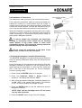
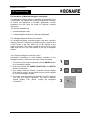
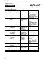
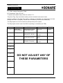
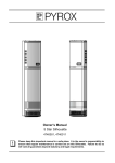
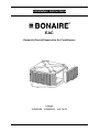
Installation Instructions
EAC
Domestic Ducted Evaporative Air Conditioners
Integra
VSS50/55, VSM60/65, VSL70/75
Installation Instructions
Table of Contents
1. INTRODUCTION ____________________________________________________ 4
1.1.
Important Notes ____________________________________________________ 4
1.2.
Dealer / Installer Responsibility ________________________________________ 4
1.2.1.
1.2.2.
1.2.3.
1.3.
Training _____________________________________________________________ 4
Legal & Statutory obligations_____________________________________________ 4
Safety and O.H. & S. Requirements _______________________________________ 5
Before Commencing ________________________________________________ 5
2. UNIT LOCATION ___________________________________________________ 6
3. UNIT INSTALLATION ________________________________________________ 7
1.1.
Installing the Dropper Duct ___________________________________________ 7
3.2.
Installing the Enviroseal Duct Shutter ___________________________________ 8
3.3.
Installing the Air Conditioner __________________________________________ 9
3.4
Installing the Duct Work _____________________________________________ 11
4. CONNECTIONS _________________________________________________ 13
4.1 Water Management __________________________________________________ 13
4.2 Inlet Water Connections _______________________________________________ 13
4.2.1 Fitting the Float Valve_____________________________________________________ 13
4.2.2 Connecting the Water Supply_______________________________________________ 13
4.3 Drain Connections – Bonaire Aquamiser __________________________________ 14
4.3.1 Fitting the Bonaire Aquamiser ______________________________________________ 14
4.3.2 Drainage Provisions ______________________________________________________ 16
4.4 Aquamiser Wiring Diagram_____________________________________________ 19
5. COMMISSIONING _______________________________________________ 20
5.1
Water Levels _____________________________________________________ 20
5.2 Dialflow Settings _____________________________________________________ 20
5.3 Bonaire Aquamiser Settings ____________________________________________ 21
5.3.1 Setting the Draining Cycle Times (Dump Interval) _______________________________ 22
5.3.2 Setting the Drain Off delay time (Dump Delay) _________________________________ 23
5.4 Installation of Transceiver______________________________________________ 24
5.5 Pairing the Navigator Controller (Remote Only) _____________________________ 24
5.6 Operation of Multiple Navigator Controllers ________________________________ 25
5.6.1 Multiple Wireless Remote Controllers ________________________________________
5.6.2 Joining Navigator Controller (JOin) __________________________________________
5.6.3 Accessing Installer Navigator Controller Setups ________________________________
5.6.4 Navigator Controller Parameters Table _______________________________________
25
25
26
27
5.7 Navigator Controller Installation – Evaporative Cooler ________________________ 28
5.7.1 Accessing Evaporative Cooler Installer Setup __________________________________ 28
5.7.2 EAC Installer Parameters Table_____________________________________________ 29
BONAIRE EAC
Page 2
Installation Instructions
Table of Contents
5.7.3 Multiple Controllers – Shared Zones _________________________________________
5.7.4 Single EAC In Shared Zone (2 Wired Navigators) _______________________________
5.7.5 Single EAC In Shared Zone (2 Remote Navigators) _____________________________
5.7.6 Single EAC In Shared Zone (3 or 4 Navigators) ________________________________
30
30
30
30
5.8 Fan Operation_______________________________________________________ 31
5.9 Controls ___________________________________________________________ 31
5.10 Customer hand Over ________________________________________________ 31
5.11 Commissioning Check List ____________________________________________ 31
6. SERVICE ______________________________________________________ 33
BONAIRE EAC
Page 3
Installation Instructions
1.0 Introduction
1. INTRODUCT ION
Please take the time to fully read this Installation manual. Failure to follow these
instructions may result in injury to you and damage to the air conditioner or your
customer’s property.
Installation of this Bonaire Evaporative Air Conditioner must conform to local building
rules and regulations, electrical and plumbing codes, Environmental Protection Authority
(EPA) regulations, and all applicable Australian Standards.
Should you not follow these instructions the unit warranty may be void. The cost of
warranty would then be the cost of the customer or the installer / dealer.
Refer to the tick box Commissioning Checklist to ensure you have covered all points
when the installation is complete. Please complete the Commissioning Checklist tick box
in the owner’s manual, as a completed, signed and dated checklist will be required to
verify certain warranty claims.
1.1. Important Notes
•
TEXT AND ILLUSTRATION COPYRIGHT CLIMATE TECHNOLOGIES 2011
•
All rights reserved. No part of this document may be reproduced or transmitted
in any form or by any means, electronic or mechanical, including photocopying,
recording or by any information storage and retrieval system, without prior
permission in writing from Climate Technologies.
•
Climate Technologies is constantly researching and developing improved
product features and therefore reserves the right to change the
specifications without notice. E. & O.E.
1.2. Dealer / Installer Responsibility
1.2.1. Training
•
It is the responsibility of all dealers to ensure their staff are adequately
trained to ensure the product is correctly specified.
•
It is the responsibility of all dealers to ensure their installation teams / subcontractors are trained in the correct installation of product, duct & fittings
as well as relevant installation codes and OH&S requirements.
•
Climate Technologies will provide technical assistance and training to the
dealer as required. On going technical support will only be provided to
those dealers and installers who attend regular training provided by
Climate Technologies.
1.2.2. Legal & Statutory obligations
BONAIRE EAC
•
It is the dealer / installer’s responsibility to comply with all codes &
standards, statutory and legal requirements, state and council / shire by
laws.
•
Relevant certificates of compliance for the installation must be issued.
Service may be refused or warranty may be void if the installation is not
compliant.
Page 4
Installation Instructions
1.0 Introduction
1.2.3. Safety and O.H. & S. Requirements
•
It is the responsibility of the dealer / installer to ensure the environment is
safe for the installer to carry out the installation. A risk assessment should
be carried out in conformance to state codes of practice. An industry guide
to “safe Work at Heights” is available from Climate Technologies.
•
It is the responsibility of the dealer / installer to ensure safe access to the
unit can be achieved for service and that the access conforms to the
relevant standards and codes.
•
It is the responsibility of the dealer / installer to ensure the roof is provided
with access footings and platform where the pitch of the roof is unsafe for
service access.
•
It is the responsibility of the dealer / installer to ensure harness anchorage
points are provided where units are located on a roof greater than single
story or if the pitch and roof construction do not allow safe access. See
Australian Standard 1891.4:2000 Part 4 Selection use and maintenance,
Table 2.1.
1.3. Before Commencing
•
Packaging – check there is no damage before removing packaging. Damaged
units should not be installed. Climate Technologies should be contacted prior to
installation. Careless transportation by installer will not be covered by warranty.
•
Do not install damaged products. Contact your nearest Climate Technologies
office for further advice.
NOTE: These 3 appliances VSS55, VSM65 & VSL75 have fan speed turn
down ability to adjust their air output to match unit sizes of VSS50, VSM60
& VSL70 as calculated in the Bonres system design. Installers should
adjust fan speed accordingly to the design requirements.
Installed damaged products will not be covered by warranty.
•
Have you got all the system components?
•
Have you got the right unit?
•
Does the system design conform to the minimum specification of Bonaire’s
specification and as such fall in line with sound engineering design practices.
BONAIRE EAC
Page 5
Installation Instructions
2.0 Unit Location
2. UN IT L OC ATION
2.1 Unit Location Check List
•
EPA - A correctly installed unit will perform to specification on sound pressure
radiated noise. As an installer, you have a professional obligation to ensure that
every practical and reasonable effort is made to install this product to best
practice guidelines and ensure that any operational noise does not affect
neighbours. Complying with EPA / council by laws for noise abates is the
responsibility of the dealer / installer / owner.
NOTE: Do not mount the unit on a section of roof that slopes towards a
neighbour’s property.
•
Place the unit well away from sources of smoke, dust and objectionable fumes so
that only clean, fresh outside air will be drawn into the unit. Reference should be
made to relevant gas codes and state plumbing regulations.
•
Check the proposed location to ensure that building members are structurally
capable of supporting the operating weight of the air conditioner. You may need
to consult the roof truss manufacturer.
•
The unit must be installed in a position that gives safe access for service. It is
the responsibility of the dealer / installer to ensure safe access to the unit can be
obtained for servicing the product.
•
Where roof height, pitch or construction will cause OH&S concerns as previously
mentioned, service footing supports / platform and or harness anchorage must
be provided for safe service.
NOTE: The manufacturer and its service providers reserve the right to
refuse service unless safety and accessibility to the unit can be
guaranteed.
•
The cost of any extra equipment required to give access to the unit for servicing
or warranty repairs is the responsibility of the owner.
The unit should face into the customer’s back yard, as low as possible on the roof, with easy,
unobstructed access. Keep the unit away from chimneys, flues and vents that will pollute the
filter pads and the fresh air being drawn into the house.
BONAIRE EAC
Page 6
Installation Instructions
3.0 Unit Installation
3. UN IT IN ST ALL AT ION
1.1. Installing the Dropper Duct
All Bonaire Fresh Air Conditioners are designed to be fully supported by a metal
dropper duct. Metal dropper ducts must be designed, located and fixed to comply with
the relevant building codes. Plastic dropper ducts are not recommended for use.
Recommended Dropper Sizes
Model
Dropper Duct Size
VSS50/55
VSM60/65
550mm x 550mm
VSL70/75
550mm x 800mm
Dropper Duct Height - Roof
Roof Pitch
Clearance Height
17°
165 mm
22.5°
185mm
25°
195 mm
36°
240mm
•
Use the recommended dropper duct as advised above.
•
The dropper must be installed square and level.
•
It should not touch ceiling joists or other structural members that allow noise and
vibration to be transmitted into the building.
•
Ensure the dropper duct is installed so the unit does not touch the roof.
•
Fix the duct dropper to the roof structure so that it’s secure and vibration free.
•
All droppers must be fitted with a splitter pyramid in the base to ensure correct
airflow.
•
All ductwork, electrical cables, water pipes and drains must be fully flashed and
sealed to prevent the entry of water into the building.
•
Plastic dropper ducts should not be used as these may void warranty.
BONAIRE EAC
Page 7
Installation Instructions
3.0 Unit Installation
3.2. Installing the Enviroseal Duct Shutter
STEP 1
The Enviroseal duct shutter must be
installed a minimum of 150mm below the
top of the dropper duct. If the dropper duct
is fitted with insulation, remove insulation to
give the shutter free operation.
STEP 2
Ensure the Enviroseal is secured
horizontally on both angles.
STEP 3
Ensure electrical cables are not draped
across the top of the Enviroseal
mechanism
STEP 4
Ensure the Enviroseal is installed the correct way up. The Enviroseal flaps
must open downwards.
For more details refer to instructions in the Enviroseal kit.
BONAIRE EAC
Page 8
Installation Instructions
3.0 Unit Installation
3.3. Installing the Air Conditioner
•
Remove 4 Louvre panels from unit and place in a safe place to ensure no
damage. To remove Louvre:
STEP 1.
Lift the Louvre assembly up approximately 15mm over the corner
post location.
STEP 2. Tilt the Louvre back from the top of unit and remove.
•
The venturi / fan assembly can be removed to assist in carrying the unit on the
roof. To remove the fan / venturi assembly:-
STEP 1.
Disconnect the motor loom from the control box in unit.
Caution: Ensure motor wires are reconnected
otherwise the product warranty may be void.
correctly
It is also possible to remove the electrical control box and
pump assembly to avoid disconnecting the electrics.
STEP 2.
Remove fan / venturi assembly by releasing the venturi from the
location notches lifting vertically. (There are 4 location notches
holding the venturi in place.)
STEP 3.
Carefully remove fan from the cabinet, not bumping the fan
assembly.
BONAIRE EAC
Page 9
Installation Instructions
3.0 Unit Installation
NOTE: Handle the fan/venturi assembly with care, as the fan blade is not
protected by the venturi once removed.
• Store the fan / venturi assembly in a safe
area until final installation to ensure no
damage. Store the fan upside down (on
the motor) ensuring no damage to the fan
assembly. (Do not store in the gutter.)
NOTE:
Warranty claims for damaged motors, impellers or venturis will not
be recognised if the motor / venturi have been damaged during
installation.
•
Lift unit chassis onto the roof. When locating the unit onto the dropper duct,
ensure the water reservoir is on the low roof side of the dropper duct.
•
Fit the unit level on the dropper duct to ensure even water distribution.
•
Check the unit is located correctly on the dropper duct. Locate the unit on the
correct chassis duct location points for the appropriate dropper duct size. The unit
should be central on the dropper duct.
•
Fix the unit into position with self-tapping type screws by screwing through the
unit duct adaptor flange and into the dropper duct. A minimum of 4 screws should
be used on each accessible side of the unit.
BONAIRE EAC
Page 10
Installation Instructions
3.0 Unit Installation
•
Lift the fan deck onto the roof and reinstall into the unit. Ensure the venturi is
correctly rotated for the motor wiring loom and has snapped into the location
notches. Spin fan blade by hand to ensure that the blade does not touch the inlet
ring.
•
Reconnect the fan loom to the control box.
•
Connect communication cables to the control box
•
Feed the communication cable and the 240-volt plug and cable set through the
50mm electrical entry drilled into the dropper duct. Ensure the 50mm rubber
grommet supplied is used to ensure an electrical hazard is not created.
3.4 Installing the Duct Work
•
Use only insulated ductwork to a thermal resistance of insulation
minimum of R1.0, designed and installed to ‘BONRES’ System
Design guidelines. All bends must have a minimum radius of 1.5
times the diameter. All joins must be taped airtight.
•
Flexible ductwork connected to the dropper duct must be designed and installed
to the ‘BONRES’ System Design Guide in conjunction with industry based best
guidelines.
•
Cut flexible duct to the correct length to ensure no excess duct is left in the
system. This will ensure minimum system resistance and maximum air flow.
•
All duct work should be streamlined. Avoid sharp angles that will reduce airflow.
•
The minimum bend radius is 1.5 times the duct diameter
•
The last bend to each ceiling register must be a smooth radius so that airflow is
even into the room.
•
Do not squash duct work to fit through small openings, as airflow will be
restricted. Find a better location.
•
If more than 6 metres of flexible duct work are required in one length, the next
size up flexible duct must be used.
•
All duct work in ceiling spaces or hot areas must be well insulated.
•
All external exposed duct work must be weatherproofed.
•
All duct work must be taped airtight.
BONAIRE EAC
Page 11
Installation Instructions
3.0 Unit Installation
The last bend to each ceiling register must be a smooth radius
so that airflow is even into the room
BONAIRE EAC
Page 12
Installation Instructions
4.0 Connections
4. C ONNECT ION S
4.1 Water Management
• Water bleed rates or the drain cycle times must be set to a rate appropriate to the local
supply water conditions. No scaling should be evident where the drain cycle / bleed rates
are set correctly. This will ensure maximum cooling and filter pad life, reduced opportunity
for scaling and therefore less regular maintenance.
NOTE: Where water quality is of high mineral content e.g. bore water, bleed off will be
required in conjunction with a regular timed draining cycle.
4.2 Inlet Water Connections
4.2.1 Fitting the Float Valve
STEP 1
Remove nut from float valve assembly.
STEP 2
Ensure rubber washer is fitted inside the tank on the float valve. Fit float valve
assembly in tank.
STEP 3
Fit nut to the valve on the underside of the tank. Do not over tighten.
NOTE:
In areas of low water pressure it may be necessary to remove the water flow
restrictor from the inside of the valve. Minimum water pressure required to
operating the float valve is 100 kPa.
STEP 4
After the nut has been tightened, ensure the ball
is not contacting the filter pad, the side of the
base of the unit or the Bonaire Aquamiser. It
should be positioned central.
STEP 5
Fit elbow supplied to the float valve.
STEP 6
Fit the 24-Volt AC water solenoid valve to the
elbow (Direction- Horizontal Not vertical).
STEP 7
Fit Flexible Connector to solenoid valve
4.2.2 Connecting the Water Supply
• The water supply pipe work and connection to the evaporative air conditioner must be
installed by a licensed plumber and conform to AS 3500, state & local plumbing
regulations.
• Ensure water pressure to the appliance does not exceed the maximum static pressure of
500kPa (50 m head) as per AS 3500 (section 3.3)
• Unit water connection is a ½” BSP fitting. Use the flexible connector supplied for the
connection between the isolating cock and the solenoid / float valve.
NOTE: In areas where water pipes freeze, a low level drain tap or pressure expansion
control valve provision will be needed to drain the water piping to prevent damage to
the air conditioner. The customer should also be advised on its operation by the
dealer / installer.
BONAIRE EAC
Page 13
Installation Instructions
4.0 Connections
• Ensure the water supply pipe is of the correct length and is secured to prevent tension on
the solenoid / float valve fittings.
• The supply pipe should be 12mm copper pipe or similar approved. A ¼ turn ball isolating
valve must be installed on the supply pipe near the unit for ease of maintenance. Do not
use duo or non-return valves of any kind including stop taps with jumper washer.
NOTE: Non return type valves can have an effect on the operation of the water
solenoid valves. Lock up and damage can be caused. Non return valves are not
required as the product conforms to MP52 Spec 101:2001 Plumbing safety licences.
• Ensure connection in to cold water supply.
• Before connecting the supply pipe flush it of any swarf or debris that may cause the float
valve or solenoid to leak.
NOTE: Failure of the Solenoid valve or Ball Float due
to debris or swarf will not be covered by warranty and
is therefore the responsibility of the installer / owner.
4.3 Drain Connections – Bonaire Aquamiser
4.3.1 Fitting the Bonaire Aquamiser
The Bonaire Aquamiser connection size is 2” BSP.
STEP 1 Remove the rubber washer from Bonaire Aquamiser Assembly.
STEP 2 Place the rubber washer under basin and fit the Bonaire Aquamiser assembly.
NOTE: The Aquamiser sticker must face the corner post and solenoid lead
must not be touching ball float.
STEP 3 Fit the drain fitting to the Bonaire Aquamiser thread on the underside of the tank and
tighten ensuring no leaks.
Select appropriate drain connection for your local plumbing regulations (40mm
Recommended)
25-19mm
Fitting x1
The Bonaire Aquamiser Kit should include
1 of each of the following items:
20mm Fitting x1
40mm Fitting x1
2” BSP
Connector x1
Seal x1
BONAIRE EAC
Page 14
Installation Instructions
4.0 Connections
When the drain
fitting components
are assembled
together, it should
look like the above
40mm option
20mm option
25-19mm option
To use the 25mm option on this
fitting, simply cut off the 19mm
tail as shown
Screw the drain fitting onto the Bonaire
Aquamiser from the underside of the tank
as shown
BONAIRE EAC
Page 15
Installation Instructions
4.0 Connections
4.3.2 Drainage Provisions
The discharge pipe must have an internal diameter of no less than the internal diameter of the
unit connection provision supplied by the manufacturer. Provided are a 40mm, 20mm and a 2519mm fitting for the Bonaire Aquamiser. The following diagrams are typical and provide
guideline for drainage connections to the evaporative cooler in accordance with the plumbing
regulations and standards.
Note: Discharge water must be managed in accordance with State and Local Government
statutory requirements and local by laws.
ECO FRIENDLY
SUGGESTION
For water conservation
purposes, the waste
water from the
evaporative unit could
be stored and used at a
later date for watering
pot plants.
OPTION 1 A discharge point to a roof gutter
pop outlet, providing the downpipe is not
used for the collection of water for potable
use
OPTION 2 Direct to downpipe via a
tundish, providing the downpipe is
not used for the collection of water for
potable use
OPTION 3 A surface stormwater drainage system
provided the surface is graded away from the building and
ponding does not occur and the discharge does not
present a safety risk to pedestrians (eg. across a
footpath)
BONAIRE EAC
Page 16
Installation Instructions
4.0 Connections
OPTION 4 A sanitary drainage system via
a tundish in one of the following forms in
accordance with AS/NZS 3500.2.2 - 1996
clause 4.6.7.8 & 11.22.
i) To a floor waste gully
ii) Direct to sanitary drain
OPTION 5 An absorption pit. Provided the
following conditions can be met:
• Only permitted where no sanitary or
surface water drainage is available.
• The pit can only be constructed in
permeable ground
• Of a size appropriate for the volume of
discharge
• Located so the discharge water will not
cause damage to buildings by changing
moisture conditions
OPTION 6 To a suitable water spreader
•
•
•
Tiled rooves only
Spreader design should be such that water
will not spill over the gutter
Providing the roof is not used for the
collection of water for potable use
BONAIRE EAC
Page 17
Installation Instructions
4.0 Connections
STEP 4
Fit the 240V cable between the solenoid and the control box routing it through the
electrical post inside the tank. Connections are not colour specific.
Ensure cables are not submerged in water!
Aquamiser
Connection
240V
Power
Supply
STEP 5
Connect electrical wiring from the Bonaire Aquamiser to the Control Box as shown
below
Control Box
Solenoid Loom
Aquamiser Loom
(2 Wires)
(4 Wires
Sheathed)
Electrical post
(Solenoid Loom to be
routed through here)
Bonaire
Aquamiser
BONAIRE EAC
Solenoid Valve
Page 18
Installation Instructions
4.0 Connections
4.4 Aquamiser Wiring Diagram
Control Box
BONAIRE EAC
Page 19
Installation Instructions
5.0 Commissioning
5. C OMMISSIONIN G
5.1 Water Levels
Aquamiser
overflow
Water Level 65 – 70mm below
overflow window on the Aquamiser
STEP 1
Turn the water on to unit and allow unit to fill. The water level should be 65mm to
70mm from the overflow window on the Bonaire Aquamiser
STEP 2
Turn the unit on and set the pre-cool function. This will activate the solenoid valve
and allow time to check the float valve setting.
STEP 3
Adjusting the float valve ball: While the float valve ball is factory set some
adjustment may be required. Adjust with care. To adjust the water level, simply
screw the ball up or down the thread on the arm. (Do Not Bend the ARM)
STEP 4
Fit Louvre panels and check for even wetting of the filter medium.
5.2 Dialflow Settings
Filter Rate – Outer Knob
• Ensure the filter knob is opened to get water
flow to the distributor. Turn Filter anti
clockwise to increase water flow.
• If water lift off is noticed, the flow rate can be
adjusted. Turn anti-clockwise to reduce the
flow to the distributor.
Bleed off Rate (if required) – Inner Knob
• All evaporative air conditioners need some water
bleed-off to prevent build-up of mineral deposits
in the system. The correct setting of the bleed
rate will ultimately govern the life of the unit.
• With normal mains water supply, bleed rate should be adjusted so that the discharge is not
less than 10 litres per hour. Increased water hardness may require a higher bleed rate and
increased maintenance
BONAIRE EAC
Page 20
Installation Instructions
5.0 Commissioning
• A bleed off may not be required if the Bonaire Aquamiser is fitted and the water quality is
below 300ppm. In which case the bleed rate should be set to completely off and the hose
secured in bottom of basin.
• Always set the bleed rate after the flow rate has been determined.
• To set the bleed rate, hold the filter flow knob (Outer) at its current setting while adjusting the
bleed rate (Inner Knob).
Fit Bleed Pipe into
the lid as shown
Bleed Pipe is now
fitted correctly
NOTE: It is the responsibility of the installer / owner to set a correct bleed rate (If
required) to suit local water conditions and ensure that rate is maintained.
5.3 Bonaire Aquamiser Settings
Correct water management in an evaporative air conditioner is vitally important to the operation
and longevity of the product. If the water management is not set correctly by the installer to the
local water condition, warranty will be void. Maintaining correct water management is the
responsibility of the owner of this appliance and warranty will also be void if correct settings are
not maintained.
BONAIRE EAC
Page 21
Installation Instructions
5.0 Commissioning
• Where a Bonaire Aquamiser is fitted and is set up for regular timed draining periods during
operation, the bleed may not need to be switched off. Check the water quality and if it is
below 300ppm Total Dissolved Solids (TDS), timed draining periods will be all that is
necessary to maintain TDS concentration levels. Over 300ppm TDS you may need a
combination of both bleed and drain. Please contact our technical support for more
information if needed. (www.bonaire.com.au)
• Where a Bonaire Aquamiser is only used for the purpose of a dry sump when not in use, the
bleed rate will have to be set for the conditions of operation.
5.3.1 Setting the Draining Cycle Times (Dump Interval)
In the setting of Draining Cycle Times, Navigator Control
must be in the OFF mode. To set the Draining Cycle Time,
1. Press and hold the ENTER button for 3 seconds.
2. Press and release the “UP”, “DOWN”, and “SETUP”
buttons in sequence.
3. The word “InST”, “nSTA”, “STAL”, “TALL”, “ALLE”,
“LLER” (Installer) will scroll across the upper part of
the display. Press the ENTER button now to access.
4. When the CodE “11 11” appears input the code “98
76” using the UP/DOWN buttons and ENTER button
to move on to the next digit.
5. The display will flash the type of unit and address of
the unit. For example “EC 53” (EC- Evaporative
cooler, 53- Different number for every Unit) and “1
1 1”
parameter on the screen. Press the ENTER button to
go to the”1 1” parameter.
6. The display will flash the first number “1”. Move to
parameter “3” by pressing the UP/DOWN button then
press the ENTER button.
7. The display will flash the second number “1”. User
can set “0, 1, 2, 4, 8 or 12” hours by pressing
UP/DOWN button. The default dumping time is 4
hours.
8. Press ON/OFF button to finish.
The draining cycle times have now been set.
BONAIRE EAC
Page 22
Installation Instructions
5.0 Commissioning
5.3.2 Setting the Drain Off delay time (Dump Delay)
DRAIN OFF Delay Time gives the option for immediate
draining of the water from the tank or a one hour delay after
the unit has been turned OFF. Setting the 1 hour delay is
preferable if the unit is going to be used in thermostat (AUTO)
mode. To set the 1 hour delay:
1. Press the ENTER button for 3 seconds.
2. Press the “UP”, “DOWN”, and “SETUP” buttons in
sequence.
3. The word “InST”, “nSTA”, “STAL”, “TALL”, “ALLE”,
“LLER” (Installer) will scroll across the upper part of
the display. Press the ENTER button now to access.
4. When the CodE “11 11” appears input the code “98
76” using the UP/DOWN buttons and ENTER button
to move on to the next digit.
5. The display will flash the type of unit and address of
the unit. For example “EC 53” (EC- Evaporative
cooler, 53- Different number for every Unit) and “1 1”
parameter on the screen. Press the ENTER button to
go to the “1 1” parameter.
6. The display will flash the first number “1”. Enter “1” by
pressing the UP/DOWN button and press the ENTER
button.
7. The display will flash the second number “1”. User
can set “0, 1” value by pressing the UP/DOWN
button. Set “0” for immediate draining of water from
the tank or “1” for 1 hour dump delay. (If an
Aquamiser is connected the user can set “0, 1, 2, 3,
4, 5” hours dependant on Hour setting parameter).
The default HOUR is 1 and default day is 1.
8. Press ON/OFF button to finish.
NOTE: It is the responsibility of the installer to set the
correct draining period to suit local water conditions.
BONAIRE EAC
Page 23
Installation Instructions
5.0 Commissioning
5.4 Installation of Transceiver
The transceiver cable connects to the control box as shown.
RF Transceiver & cable
assembly
Fully extend the transceiver cable (4 meters) and attach the
transceiver housing to a solid surface such as a rafter or
vertical column using the two screws provided. Avoid direct
contact with metal surfaces. Connect the transceiver plug to
one of the two thermostat connections on the control box.
When the installation is complete and the power to the cooler
is turned on, a green LED in the transceiver case should be
visible confirming it is connected correctly and is ready for
pairing with a Navigator controller.
Navigator Controller & Transceiver
Connections
To ensure trouble free operation, the transceiver
housing & connecting cable should not be installed
within 200mm of any power cables or other radio
transmitting devices. The transceiver housing should be
placed 1m away from any metal object.
Do not screw the transceiver to the back of the
control box; it must be run into roof space.
5.5 Pairing the Navigator Controller (Remote Only)
The BONAIRE Navigator Controller and transceiver does not
have any pairing information when they are delivered from
the factory.
On the first power up, the transceiver will request to PAir with
Navigator Controller for period of a 30 min window and its
green light will be illuminated. If it does not PAir within that
time, it will PAir on the next power up. Put the Navigator
Control in pairing mode 1. Press & hold the ENTER button for 3 seconds.
2. Press the Heat/Cool, Mode & Setup buttons in
sequence. The display will flash the “PAir”.
3. After a few seconds the Navigator Controller displays the
“ro XX” (“XX” is the unique serial number. For example
“ro 22”). It will also display the strength of signal.
4. Press the ENTER button to pair the transceiver and the
Navigator Controller.
NOTE: Wait until the backlight turns off and press
any key after 2 minutes.
5. Press the ON/OFF button to go to the main display.
BONAIRE EAC
Page 24
1
2
3
Installation Instructions
5.0 Commissioning
5.6 Operation of Multiple Navigator Controllers
The Navigator control system is capable of supporting up to
4 controllers. By default, the system will allow one controller
to control the appliance or multiple appliances. Certain
parameter set ups must be made to configure multiple
controllers.
The options available are
• 2 wired Navigators only
• 1 wired Navigator and up to 3 Remote Navigators.
5.6.1 Multiple Wireless Remote Controllers
In a multiple Navigator controller system, the other controller
may be joined to a master by putting the slave controller into
a PAir mode. It will then send out a PAir request to the
master controller. The master controller is then put in a JOin
state and can then join the request to set up a Navigator
system.
5.6.2 Joining Navigator Controller (JOin)
Controllers requesting to JOIn another controller in the
Navigator system, can be put in the join mode as follows.
1. To enter the JOIn state, press and hold the ENTER button
for 3 seconds & release.
2. Press and release the, MODE, HEAT/COOL and SETUP
buttons in sequence.
3. The master wireless Remote controller should display
JOin state to receive a command from the other handset
to JOIn the Navigator system.
4. The slave controller should be placed into a Pair state to
join with the master controller. The slave controller
should display Pair. (Refer “Paring the Navigator
Controller”).
BONAIRE EAC
Page 25
1
2
3
Installation Instructions
5.0 Commissioning
5.6.3 Accessing Installer Navigator Controller Setups
NOTE: The Navigator Controller must be in the OFF
status to enter into the setup mode.
1. Press and hold the ENTER button for 3 seconds.
2. Press & release the then then SETUP buttons to
enter the installer set up mode.
3. The word “InST”, ”nSTA”, ”STAL”, ”TALL”, ”ALLE”, ”LLEr”
(Installer) scrolls across the upper part of the display.
Press the ENTER button.
4. When the CodE “11 11” appears, then set the code to
“98 76” using the and buttons to select each digit,
and press the ENTER button to move to the next digit
NOTE: The Navigator Controller will display the
abbreviated name of the appliance such as
“EC XX” for Evaporative Cooler, “HE XX” for
Central Heater or “th XX” for the Navigator
controller settings (“XX” is the unique serial
number). For example “th 06”.
5. Use the and buttons to scroll to the “th XX” and
then press the ENTER button to access Navigator
Installer setup.
The display will now show digits “1 1”. The lower left digit
is the parameter number and the lower right digit is the
parameter option value. Parameter numbers and option
values can be found in the Navigator Controller Installer
Parameters Table.
6. To select the parameter number use the and buttons to find the desired parameter and press
ENTER.
7. Adjust the option value (See Navigator Parameter
Table) to the required value and press ENTER. This
will set the option value and return you to the
parameter number selection menu.
8. When finished press the ON/OFF button to exit.
BONAIRE EAC
Page 26
Parameter
Number
Options value
Installation Instructions
5.0 Commissioning
5.6.4 Navigator Controller Parameters Table
th parameter Table (“th XX”)
Parameter
Description
Default
1
Un switched
Zone Option
1
Definition
Options Values
Tells system if
there is a common
zone present
1= common zone
present.
0= no common zone
(Note that a cooler is
usually installed into the
common zone)
2
Switched
Zones
15
To display all
available switched
zones
15= Zone 1, 2,3 & 4
6 = Zone 2&3
127 = 8
Using ZONE and buttons whilst in this
parameter will set the
number
3
4
5
Temperature
Display zone
0
Temperature
Measurement
-Un switched
Zone option
1
Temperature
Measurement
- Switched
Zones
15
6
Not Used
7
Not Used
8
RF Network
Not Used
BONAIRE EAC
0 –Common zone
Determines if the
navigator is
measuring the
temperature in the
common zone
1Measuring common
zone.
Determines which
of the switched
zones the
Navigator is
measuring,
15= Zone 1, 2,3 & 4
The current RF
network number
0 = not assigned
1-8 Zones 1-8
0= Not measuring
common zone
6 = Zone 2&3
127 = 8
Using ZONE and buttons whilst in this
parameter will set the
number
0
0
(RF handset
only)
0
Selects which zone
the Navigator will
display the
temperature of
0
Page 27
Any other = actual
network
Installation Instructions
5.0 Commissioning
5.7 Navigator Controller Installation – Evaporative Cooler
5.7.1 Accessing Evaporative Cooler Installer Setup
NOTE: The Navigator Controller must be in OFF status
to change the parameters.
1. Press and hold the ENTER button for 3 seconds.
2. Press & release the then then SETUP buttons
to enter the installer set up mode.
3. The word “InST”, ”nSTA”, ”STAL”, ”TALL”, ”ALLE”,
”LLEr”(Installer) will scroll across the upper part of the
display. Press the ENTER button now to access.
4. When the CodE “11 11” appears input the code “98
76” using the or buttons to change each digit,
and press the ENTER button to move on to the next
digit.
NOTE: The Navigator Controller will display the
appliance controller ID “EC XX” for an
Evaporative Cooler (“XX” is the unique ID
number).For example “EC 53”.
5. Press the ENTER button when “EC XX” appears.
The display will now show digits “1 1”. The lower left digit
is the parameter number and the lower right digit is the
parameter option value. Parameter numbers and option
values can be found in the EAC Installer Parameters
Table.
6. To select the parameter number use the or buttons to find desired number and press ENTER.
7. Adjust the option value (see EAC parameter table) to
the required value and press ENTER. This will set
option value and return you to the parameter
selection menu.
8. When finished press the ON/OFF button to exit.
BONAIRE EAC
Page 28
Parameter
Number
Options Value
Installation Instructions
5.0 Commissioning
5.7.2 EAC Installer Parameters Table
EC Parameters Table (“EC XX”)
To access the installer setups refer the section 5.7.1.
*Day Hour Flag. Only used where salinity sensor and water level sensor used.
Incorrect setting of this flag may result in damage to the EAC, its components and also
damage can occur to property. This will not be covered by manufacturer’s warranty.
The Days option is not to be used for the Sump dump valve system.
The Days option can be used if the EAC is operating on rainwater (low TDS)
Parameter
Action
Definition
Options/Values
Default
1
Drain delay
after shut down
Delay between pump
off and water drain.
0 or 1 Hr
1 Hour
2
Pre Cool time
90 second pre cool
after pre fill – No fan
0 = Off
On
1 = On
3
Drain Interval
Run time between
forced drain periods.
1-12Hrs / 1-12
Days*
4 Hours
4
Pre fill time
60 second pre fillSolenoid - No pump
0 = OFF
On
1 = On
5
6
7
8
9
DO NOT ADJUST ANY OF
THESE PARAMETERS
10
11
BONAIRE EAC
Page 29
Installation Instructions
5.0 Commissioning
5.7.3 Multiple Controllers – Shared Zones
This feature enables all the Navigator Controllers connected to the system to be assigned to
all the zones on the system (either switched or unswitched).
Any key press that changes the operating state or operating condition on any one of the
controllers will be reflected on the other controllers on the Navigator control system.
5.7.4 Single EAC In Shared Zone (2 Wired Navigators)
With two Navigators, you need to ensure that only one Navigator controller is measuring the
temperature for the common/ shared zone.
No modifications are required to Navigator 1 parameters but Navigator 2 will require
parameter changes. The installer will need to set parameters as below,
Navigator Controller 2 Installer Parameters
Parameter
Id
Value
Meaning
Temperature Measurement
Common Zone
– 4
0
No measurement from common zone
Temperature Measurement
Switched Zones
– 5
0
No measurement from switched zones
All temperature measurement from Navigator 2 is now disabled
5.7.5 Single EAC In Shared Zone (2 Remote Navigators)
1. Pair the Navigator Controller 1 to the Transceiver as for a normal single thermostat
installation.
2. Put Navigator 2 into the “Pairing state” (Refer “Pairing the Navigator Controller).
3. Put Navigator 1 into “Joining Mode” (Refer “Joining Navigator Controller”)
4. Navigator 1 should display “Join” and Navigator 2 should display “Pair” and then the
network will be joined.
NOTE: No modifications are required to Navigator 1. With two Navigators, you need to
ensure that only one is measuring the temperature for the common/ shared zone.
Remote Navigator 2 will require parameter changes. The installer will need to set
parameters as per the table above.
5.7.6 Single EAC In Shared Zone (3 or 4 Navigators)
Set up primary and subsequent controllers (wired wall mounted or wireless remote) as
above, ensuring all subsequent controllers are set to not measure temperature.
BONAIRE EAC
Page 30
Installation Instructions
5.0 Commissioning
5.8 Fan Operation
• Check the fan is clear of the venturi.
• Set the fan running.
• Check that the air is being evenly distributed through the ductwork.
• Make adjustments, as required, to any manual air dampers that may be fitted.
5.9 Controls
• Refer to your control installation and commissioning instructions.
5.10 Customer hand Over
Instruct the customer in the use of the product.
• Controls
• Bleed off
• Venting/Exhausting the air via the side of the home the wind is not blowing from.
• Maintenance Requirements
Hand over of the customer’s operational manual with the commissioning check list
completed.
5.11 Commissioning Check List
You must complete, date and sign the ‘tick box’ checklist in the owner’s manual. Use
this copy to check the installation prior to completing the owner’s documentation.
Unit
All equipment ordered by the customer is installed.
The unit is level and secure.
The water supply line has been flushed to clear swarf and debris and is free of
leaks.
The tank is free of foreign matter and debris. The water isolating tap is turned ON.
Water drainpipe work is completed and sealed.
The fan assembly is correctly located and the fan blade spins freely in the venturi.
The mains and control wiring are complete and the circuit breaker and GPO are
turned ON.
The minimum & maximum fan speeds are correctly set.
The water basin fills with water and the float valve closes correctly when the water
level is 65-70mm below the overflow level.
BONAIRE EAC
Page 31
Installation Instructions
5.0 Commissioning
The water pump operates correctly when turned ON at the controller.
The Aquamiser cycle times and / or dialflow water bleed rate are set to suit local
water conditions.
Aquamiser drain valve is operating correctly and the tank drains correctly when unit
turns off.
The fan operates through the entire speed range.
Water distribution is even with the filter pads fitted and the air conditioner operating
pump and fan.
All Controller functions for the appliance operate
Ductwork and general
The Enviroseal functions correctly with the shutters opening downwards at 90°
All roof penetrations are fully sealed and watertight.
All ductwork is completed to plan, correctly supported and airtight, with no bend
tighter than 1.5 x the ductwork diameter.
Air distribution checked, dampers are adjusted and all outlets correctly adjusted and
wiped clean.
Man hole cover replaced.
All rubbish has been removed from inside and on the roof.
Site
Customer Hand Over
You have explained the following to the customer:
The operation of the Controller.
The need to open windows and doors for the correct operation of Evaporative Air
Conditioning
The operation of the bleed or dumping system and it’s importance to operate all the
time
Stick the Serial Number Label of the unit in the owners manual
Maintenance requirements
BONAIRE EAC
Page 32
Installation Instructions
6.0 Service
6. SER VIC E
A qualified service technician should conduct any service work carried out on this ducted
cooling product. It is important that periodical service is carried out on the product to ensure
the customer receives the efficiency benefits the product provides.
Only an authorised Climate Technologies service provider can carry out warranty service.
For Metro Service only ring the numbers below
South Australia
1300 665 087
Email: [email protected]
New South Wales/
1300 665 087
Email: [email protected]
Queensland
Australian Capital Territory
1300 665 087
Western Australia
1300 665 087
Email: [email protected]
Victoria/Tasmania
(03) 8795 2456
Email: [email protected]
Mobile Callers all states
03 8795 2460
Outside Metro areas please contact your nearest Climate Technologies Service Provider
BONAIRE EAC
Page 33
Manufactured by
Climate Technologies
ABN 13 001 418 042
26 Nylex Avenue
Salisbury, SA 5108
Australia
www.bonaire.com.au
6062217D