1
Coca-Cola
Marketing Machine
Parts
Service
Troubleshooting
Manual
Beginning Serial Number 0001-6501BW
June 1998
Dixie-Narco Blvd.
P.O. Drawer 719
Williston, SC 29853-0719
INDEX
General Information ............................................................................................................... Pages 3 through 5
Installation & Set-Up............................................................................................................. Pages 6 through 10
Hardware Configuration & Features.................................................................................... Pages 11 through 13
SIID Audit Features............................................................................................................ Pages 14 through 18
Controller Programming..................................................................................................... Pages 19 through 31
Programming Quick Reference...............................................................................................................Page 32
Electrical Parts & Their Functions ...................................................................................... Pages 33 through 37
Product Shimming .................................................................................................................................Page 38
Adjustments: Cams/Rear Spacers..................................................................................... Pages 39 through 42
General Maintenance................................................................................................................. Pages 43 and 44
Trouble Shooting Flow Charts............................................................................................ Pages 45 through 57
Trouble Shooting Examples............................................................................................... Pages 58 through 64
Vending ........................................................................................................................... Pages 58 and 59
Coin/Currency.................................................................................................................. Pages 60 and 61
Sold-Out Message.........................................................................................................................Page 62
Select Panel/Display......................................................................................................... Pages 63 and 64
Refrigeration Parts & Functions ......................................................................................... Pages 65 through 69
Refrigeration Cycle ................................................................................................................................Page 70
Refrigeration Trouble Shooting .......................................................................................... Pages 71 through 76
Product Hot - Compressor will not run...........................................................................................Page 71
Product Hot - Compressor starts but will not keep running............................................................Page 72
Product Hot - Miscellaneous..........................................................................................................Page 73
Product Cold But Not Cold Enough - Compressor runs but won’t cool product..............................Page 74
Product Too Cold or Frozen - Compressor runs too long or continuously......................................Page 75
Noisy Refrigeration Unit................................................................................................................Page 75
Excessive Condensate..................................................................................................................Page 76
Glossary ................................................................................................................................................Page 77
Electrical Schematics........................................................................................................ Pages A1 through A6
Phone:
Phone:
FAX:
WILLISTON, SC
(800) 688-9090
(803) 266-5000
(803) 266-5150
GENERAL INFORMATION
VENDER SAFETY PRECAUTIONS
Please read this manual in its entirety. This service information is intended to be
used by a qualified service technician, who is familiar with proper and safe
procedures to be followed when repairing, replacing or adjusting any DixieNarco vender components. All repairs should be performed by a qualified
service technician who is equipped with the proper tools and replacement
components, using genuine Dixie-Narco factory parts.
Repairs and/or servicing attempted by uninformed persons can result in hazards
developing due to improper assembly or adjustments while performing such
repairs. Persons not having the proper background may subject themselves to
the risk of injury or electrical shock, which can be serious or even fatal.
MODELS AND DETAILS
DNCB 168
Height:
Width:
Depth:
Shipping
Wt:
DNCB 180
Height:
Width:
Depth:
Shipping
Wt:
DNCB 276
Height:
Width:
Depth:
Shipping
Wt:
DNCB 300
Height:
Width:
Depth:
Shipping
Wt:
1439mm (56 11/16")
711mm (28 5/16")
737mm (30 1/2")
211 (464 lbs)
1439mm (56 11/16")
711mm (28 5/16")
737mm (30 1/2")
211 (464 lbs)
1829mm (72")
711mm (28 5/16")
737mm (30 1/2")
260 (574 lbs)
1829mm (72")
711mm (28 5/16")
737mm (30 1/2")
260 (574 lbs)
DNCB 348
Height:
Width:
Depth;
Shipping
Wt:
DNCB 360
Height:
Width:
Depth:
Shipping
Wt:
DNCB 368
Height:
Width:
Depth:
Shipping
Wt:
DNCB 414
Height:
Width:
Depth:
Shipping
Wt:
DNCB 440
Height:
Width:
Depth:
Shipping
Wt:
1829mm (72")
940mm (37 1/16")
737mm (30 1/2")
330 (728 lbs)
1829mm (72")
940mm (37 1/16")
737mm (30 1/2")
288 (634 lbs)
1829mm (72")
940mm (37 1/16")
737mm (30 1/2")
312 (688 lbs)
2007mm (79 1/2")
940mm (37 1/16")
737mm (30 1/2")
358 (790 lbs)
2007mm (79 1/2")
940mm (37 1/16")
737mm (30 1/2")
331 (730 lbs)
DNCB 501T
Height:
1829mm (72")
Width:
940mm (37 1/16")
Depth:
813mm (32")
Shipping
Wt:
344 (758 lbs)
DNCB 522T
Height:
1829mm (72")
Width:
940mm (37 1/16")
Depth:
813mm (32")
Shipping
Wt:
305 (672 lbs)
DNCB 600T
Height:
2007mm (79 1/2")
Width:
940mm (37 1/16")
Depth:
813mm (32")
Shipping
Wt:
381 (840 lbs)
PRODUCT IDENTIFICATION
The age of Dixie-Narco products is determined by the date code incorporated in the serial number.
The vender serial number takes the form xxxx-yyyyzz. The first 4 digits (xxxx) identify the specific vender. The next 4
digits (yyyy) identify the manufacturing run that the vender was built in. The last two alpha characters (zz) identify the
quarter and the year the vender was built. The first alpha character identifies the quarter:
A = 1st quarter
B = 2nd quarter
C = 3rd quarter
D = 4th quarter
The second alpha-character identifies the year:
T = 1995
U = 1996
V = 1997
W = 1998
X = 1999
Y = 2000
Z = 2001
SIID CAN & BOTTLE VENDER
INSTALLATION & SET-UP
The Dixie-Narco SIID can and bottle vender is designed utilizing the latest technology featuring a highly sophisticated,
micro-computer based control system. The SIID Electronic Vender is designed to meet the growing need for
accountability, multi-pricing, programmability, and system diagnostics in can vending equipment. Along with these
functions, DEX/UCS-communications to a hand-held computer is available to provide the ability to measure each vending
location for product performance, vender performance, and accessing accounting data. This data can be used to
maximize the efficiency of routes for servicing venders. DEX communications also provides the bottler security for the
integrity of the "cash in" versus the "product sold". The vender design provides the flexibility required for the changing
beverage industry as well as dependable performance for many years. This manual is prepared to assist the proper
installation and set-up of the vender. Please read this manual carefully and become familiar with the SIID Vender before
placing the vender on location.
RECEIVING INSPECTION
Upon receipt, inspect the vender for any shipping damage. If there is any damage have the driver note the damage on
the bill of lading and notify Dixie-Narco. Although I.C.C. regulations require that the consignee originate shipping damage
claims, Dixie-Narco will gladly help if you must file a claim.
UNPACKING THE VENDERS
Remove the stretch wrap and top cover from the vender. If flavor labels were shipped with your vender they will be
affixed to the back of a vender in the shipment or in the cash box.
NOTE:
DO NOT STORE THE VENDER OUTSIDE WITH THE STRETCH WRAP ON. THIS COULD CAUSE THE
STRETCH WRAP TO BOND TO THE VENDER'S SURFACE, WHICH COULD DAMAGE THE FINISH.
Remove the shipping boards from the bottom of the vender. The shipping boards are attached by the leveling legs.
Remove the shipping boards by unscrewing the leveling legs. A 1½ inch "socket type" wrench should be used on the
bottom of the leveling legs. Be sure to replace the legs after removing the shipping boards.
To open the vender, locate the door lock keys which are secured inside the coin return cup. After unlocking the door,
rotate the "T"-handle counter-clockwise until the door can be opened. Once inside, check the coin box on the door for
any additional parts, pricing labels, or information concerning factory equipped accessories. Check the "T"-handle for
proper alignment and locking functions. Check the lamps for proper installation.
ELECTRIC POWER NEEDED
Refer to the cabinet serial number plate to determine the proper voltage and frequency the machine requires
(domestically this requirement is 115 Volts, 60 Hertz). Domestic venders will operate properly at +/- 10% of the specified
voltage. For domestic models this is between 103 volts and 127 volts. The cabinet serial plate also indicates the
amperage of the vender. Single phase, alternating current is required. The vender must be plugged in its own properly
rated circuit with its own circuit protection (fuse/circuit breaker).
DO NOT USE AN EXTENSION CORD.
GROUND THE VENDER
The vender is equipped with a three wire power supply cord and MUST be plugged in a properly grounded outlet.
DO NOT REMOVE THE GROUND PIN OR IN ANY WAY BYPASS THE GROUNDING OF THE VENDER.
If the outlet will not accept the power cord plug, contact an electrician to install a proper AC outlet.
COIN CHANGERS AND OTHER ACCESSORIES
The SIID vender must have a coin changer installed and can have a bill acceptor installed. If the coin changer and other
accessories are not factory installed refer to the instructions received from the manufacturer of the coin changer and
other accessories for proper set-up and installation.
The SIID vender will support the following coin changers:
Multi-Drop Coin Mech (Domestic)
Coinco 9302GX
Mars TRC6510
BILL ACCEPTORS
If a bill acceptor is not factory installed, a bill acceptor interface harness must be ordered from Dixie-Narco. See the chart
below:
Bill Acceptor Interface Harnesses
* Also requires parts from acceptor manufacturer.
Note:
Bill acceptors will be inhibited anytime the door interlock switch is in the center position (service mode enable)
even if service mode time out has occurred restoring the vender to normal operation.
OTHER ACCESSORIES
The SIID Vender is capable of interfacing to Debit Card and Data Recording systems. At this time only a few such
accessories have been tested by Dixie-Narco. If such accessories are to be used check with either Dixie-Narco or the
accessory manufacturer about physical and electrical compatibility before attempting to interface such accessories to the
SIID Vender.
INSTALLING A COIN CHANGER
Hang the coin changer on its mounting plate and secure it by tightening the three securing screws. Plug the coin
changer into the 6 pin socket for MDB changers, in the vender.
CAUTION:
The coin changer must be plugged in with the power removed from the door or the coin changer may
not power on properly.
After restoring power, manually load the coin changer coin tubes with at least 10 coins each. Following the program
instructions for the SIID Vender, program each selection for its own vend price. A price of $0.00 is free vend. After the
pricing is set return the vender to its operate mode either by closing the door or pulling the door closed switch out.
"Prime" the coin changer by making a correct change transaction.
PLACING THE VENDER ON LOCATION
CAUTION:
DO NOT TRANSPORT THE VENDER TO OR FROM THE LOCATION LOADED WITH PRODUCT
OR DAMAGE TO THE VENDER MAY RESULT.
The vender must be located on a solid, flat, and level surface. The vender must be positioned close enough to an
electrical outlet that an extension cord is not required. If securing the vender to the floor or wall is required, call the DixieNarco Factory Service Department or your Dixie-Narco Representative for suggestions.
LEVEL THE VENDER
Level the vender. When the vender is level the door can be opened to any position and it will not move by itself. Open
the door to several different positions before deciding the vender is level.
Make sure that all of the leveling legs are touching the floor. If you cannot level the vender, select another location. Do
not place any objects under the machine.
DANGER:
The vender must be properly located and leveled to minimize the risk of injury or death from
tipping in the event of user misuse or vandalism.
SPACE THE VENDER
Do not block the rear of the vender. Keep the vender 4 inches (10 cm) from the wall to insure adequate airflow to the
condenser and compressor. At the front of the vender, make sure that nothing obstructs the air intake at the bottom of the
main door. At the rear of the vender, make sure nothing obstructs the air exhaust at the bottom of the cabinet.
LOADING THE VENDER
All SIID Venders are shipped ready to vend 12 oz. cans unless another package was specified at the time the vender
was ordered from the factory. If a package other than a 12 oz. can is to be vended contact a Dixie-Narco Factory Service
Representative, or refer to the proper technical bulletin for spacer settings and shims.
INITIAL LOADING
Oscillators must be in the extreme left or right position to insure proper loading. When loading wide columns, the first row
of cans should be loaded on the bottom bar of the oscillator. The second row of cans must be loaded on the top bar of
the oscillator. Always load complete rows, do not load only to the back or only to the front of the column. Rotors must be
in the "cup" position to receive the first cans. When loading narrow columns lay the rows in the column until the column
is full.
Do not fill the columns to the top of the cabinet. Allow about 3 inches at the top of the column because the can stack will
move up and down in the column during the vend cycle. Correct loading will prevent service calls and insure proper
vending.
After loading a vender for the first time, test vend each selection with money until the first can is delivered. This will
ensure that the vender is loaded and working properly.
NOTE:
TO INSURE PROPER AIR FLOW THROUGH THE EVAPORATOR, DO NOT PLACE CANS (OR OTHER
FOREIGN OBJECTS) IN THE BOTTOM OF THE TANK.
INSTALLING FLAVOR CARDS
The flavor cards may be inserted one of two ways: 1.) in the select buttons, or 2.) in the flavor card carrier.
1.)
IN THE SELECT BUTTONS:
Swing the coin changer mounting plate away from the outer door, exposing the back of the select
buttons. The flavor cards are inserted in the back of the select buttons from either side.
2.)
IN THE FLAVOR CARD CARRIER:
Swing the coin changer mounting plate away from the outer door, exposing the back of the select panel.
Remove the flavor card carrier. Ensure the flavor cards are placed in the select button flavor card carrier
position that corresponds to the column in which the product is loaded.
SIID
HARDWARE CONFIGURATION
The hardware configuration for the SIID Controller consists of a main control board and a display board. The select
panel consists of low voltage switches. Sold-out indicators are eliminated in the SIID. The select switches interface
directly to the main controller.
The motors used on the stack continue to be 115 VAC. The vend switches and sold-out switches are low voltage. There
is only one vend switch per motor and one sold-out switch per column. The motors, vend switches, and sold-out
switches directly interface to the main controller board. Each motor is independently controlled to provide the maximum
flexibility for space to sales. The Main Controller supports up to 10 motors and 10 selections.
The Main Controller consists of one board. It consists of all the intelligence, memory, switch interfaces, stack interface
(motors, vend switches, and sold-out switches), and peripheral interfac es which include coin changers, dollar bill
validators, DEX interface and debit systems.
The DEX interface supports both an internal connection as well as an external connection. The interconnect is a 1/4"
phono jack as specified and approved by NAMA. All electrical specifications, protocols, and baud rates are identified in
the specification.
The door switch is included to determine door accesses. A service switch is located on the main controller board to
access accounting data, programming features, and access diagnostic features through the front select panel.
A real time clock (RTC) with battery backed memory is provided so memory can be maintained during power failures.
The life expectancy is 5 years shelf life and 10 years operational. The real time clock is displayed in military time (24
hour clock). The RTC is used for time stamping door closures, power outages, limited access, and selective discount
pricing.
The intelligence of the Main Controller is an Intel 80C32 microprocessor. A minimum of 128k of EPROM and 8k of RAM
(battery backed) is provided.
Early Display Boards will consist of four 7 segment LEDs to provide alpha-numeric characters. Future Display Boards
will consist of four, fourteen segment LEDs to provide clearer alph-numeric characters. Also, the exact change indicator
consists of an LED.
FEATURES
The following is a description of all the features of the SIID.
- DEX Compatible Hand-held Interface The vending industry (NAMA) has established an audit data protocol which is defined by DEX (Direct Exchange Of Data)
and UCS (Uniform Communications Standards). This interface is a direct connect as defined by the specification. The
SIID has provisions for an internal and external connection. The external connection provides a limited amount of
information.
The internal connection provides the full capability of DEX/UCS. These capabilities include full audit of interval and
historical data, system programming, diagnostics, and limited access.
- 10 Column Stack Compatible The SIID Controller is capable of driving up to 10 stack motors independently. The motors will be 110 VAC. The vend
switches and sold-out switches are low voltage, gold cross-point switches. The interface for the cam position and empty
detection is located on the controller board.
- Low Voltage Select Panel The select panel consists of gold cross-point switches. The interface circuitry is located on the controller board. The
controller board supports up to 10 selections.
- Programmable Space To Sales Programmable space to sales is a feature which allows columns to be assigned to select buttons.
dispensed evenly when more than one column is assigned to a select button or group of select buttons.
Columns are
- Select Panel Controller Programming or
- Hand-held Controller Programming The SIID vender has the capability to be programmed through the select panel. The SIID vender can also be
programmed through the DEX port with the same hand-held used to access the accounting data.
- LED Display (Light Emitting Diodes) Optional LCD Display (Liquid Crystal Diodes)
Early displays consist of 4 characters utilizing 7 segment LEDs for each character to provide a true alpha-numeric
display. Future display boards will consist of four, fourteen segment LEDs to provide clearer alpha-numeric characters.
The display is implemented on it's own printed circuit board.
- Sold Out Message/Selection Each selection is supported by a sold-out message. When a given selection is sold-out and that selection is pressed,
"SOLd Out" will scroll across the display.
- Price Displayed when Selection is pressed The operation of the vender in the ready mode provides the customer the price of any selection when that particular
select button is pressed. If all selections are set at the same price in primary set price and the same price in secondary
set price, the vend price is displayed at all times on the display.
- Single Price or Multi-Price via Select Panel or Hand-held Prices for each selection are programmed either through the front select panel or through the DEX hand-held device.
For single price configuration, each selection has to be programmed for the same price.
- Accounting Data Provided The accounting features are accessed through the front select panel. These include (CASH) historical cash data, which
is not resettable, (CLN) resettable cash data, (SALE) historical vend data, and (SLN) resettable vend data.
(CASH)
(CLN)
(SALE)
(SLN)
Historical Data:
The total cash collected by the vender
Resettable Data:
The total cash collected for each selection.
Historical Data:
The total number of vends by the vender.
Resettable Data:
The total number of vends for each selection.
The types of data that can be retrieved via the DEX interface to a hand-held device is addressed in the SIID Audit
Features section.
- Limited Access on Selection (Time, Days, Price) The limited access feature allows each selection to be inhibited with respect to time and selected days of the week. Also,
prices of selections can be altered (Happy Hour) with respect to time and selected days of the week.
- Multiple Coin Changer Interfaces The SIID Controller supports the following coin changer interfaces.
A)
MDB
Multi-Drop Specification (USA)
- MDB Bill Validators Coinco BA-30 Bill Validators interface to the SIID Controller. Also, validators which interface to the new MDB (Multi Drop
Bus) specification should also be compatible, but have not been tested and approved as of this publication. If a bill
acceptor is not factory installed, an interface harness will need to be ordered from Dixie-Narco, and/or the bill acceptor
manufacturer.
- Verifone/Debitek Card Compatible The SIID is capable of interfacing to Debit Card and Data recording systems. At this time only a few such accessories
have been tested by Dixie-Narco. If such accessories are to be used check with either Dixie-Narco or the accessory
manufacturer about physical and electrical compatibility before attempting to interface such accessories to the SIID
vender. The SIID supports any Debit Card/Data Recording manufacturer's systems that meet NAMA II protocol.
SIID AUDIT FEATURES
The SIID provides two methods of accessing audit data. A limited amount of audit information is available in the system
set-up/audit menu. More extensive audit information is accessible electronically.
SYSTEM SET-UP/AUDIT MENU
Four types of audit data are available in the system set -up/audit menu. "CASH", which is the historical total cash counted
for the vender; "CLN", which is the resettable cash counted for each selection for the vender; "SALE", which is the
historical total number of vends for the vender; "SLN", which is the resettable total number of vends for each selection for
the vender.
The audit data is accessed by pressing select button 4 when "CASH" or "SALE" is on the display. With "CASH" on the
display, press select button 2 to scroll into "CLN". With "SALE" on the display, press select button 2 to scroll into "SLN".
ELECTRONIC ACCESS
A much more extensive amount of audit information is accessible electronically. It is retrieved with a portable data
collection device and typically loaded into a computer at a central location. The data can then be tracked with a data
base, for preparing route stocking lists, tracking cash flow, doing inventory control and other tasks. Data collection
devices are available from several sources including: Norand, Fujitsu, Panasonic, Telxon, Verifone and Mars. DixieNarco currently collects data with a PC program running on a portable notebook computer.
The SIID uses the DEX/UCS protocol as the method of exchanging data with the portable data collection device.
DEX/UCS was formally adopted as the standard method of collecting audit data for the vending industry by the National
Automatic Merchandising Association (NAMA) in April of 1991. DEX/UCS has been used in related industries since
1989. It was developed by the Arthur D. Little Company and is administered and maintained by the Uniform Code
Council (UCC). The NAMA Vending Electronics Standardization Committee developed and published a comprehensive
set of data records relevant to the vending industry. The SIID reports the portion of these related to this specific machine
design. The current list of records and their usage by the SIID follows.
DEX stands for Direct EXchange of data, which means there is a hard-wired connection between the two systems
exchanging data. This is done by inserting a ¼ inch phone plug on the portable data collection device in a jack mounted
on the SIID. Inserting the plug automatically initiates the exchange of data, which takes several seconds. No other
machine functions are available while the exchange is taking place. The operator is told that the exchange is taking
place by the display of the message "DEX IN PROGRESS". Most of the data records are reported in both an interval
and historical format. The historical values represent a total of the values since the machine shipped from the factory.
The interval values are the data collected since the last time it was collected electronically.
The following types of audit data are accessible electronically:
Machine Identity Information
Date and Time of Interrogation
Cash Sales Summary
Cash Input and Output Summary
Product Sales Information
Machine Configuration
Events:
Door Openings
Interrogations
Programmable Access Limits
Time of Day Discounts
In addition to retrieving audit data, every machine configuration parameter that can be programmed in the service menu
can be programmed electronically via the DEX port.
The following types of data can be configured electronically:
Machine Identity
Date and Time
Price and Product Information
Space to Sales
Limited Access Control Parameters
Time of Day Discounts Control Parameters
Escrow Mode *
* Escrow mode cannot be transferred with the Norand Device.
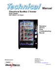
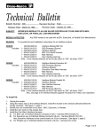
SAMPLE
SIID CONFIGURATION & ACCOUNTING
REPORT
Vender Identification:
Serial Number:
1234-6132BR
Model Number:
DNCB501T SIID
Location:
NAMA SHOW - CHICAGO, IL
Asset Number:
362436
# of Columns:
# of Selections:
8
7
Significant Events:
RECENT
Door Openings:
Power Outages:
Total Vends:
Total Sales:
HISTORICAL
2
1
12
2
10
$7.50
213
$159.75
Vender Configuration:
Coin Mechanism:
Escrow Mode:
MICRO MECH
ESCROW TO SELECT / dollar bill escrow
SELECTION
PRICE($)
HHPRICE($)
1
2
3
4
5
6
0.75
0.75
0.75
0.75
0.75
0.75
0.50
0.50
0.50
0.50
0.50
0.50
DESCRIPTION
Cola
Cola
Cola
Apple Juice
Diet Cola
Diet Cola
7
0.75
0.60
Tea
Space to Sales Configuration:
Selections:
1 Cola
2 Cola
3 Cola
4 Apple Juice
5 Diet Cola
6 Diet Cola
7 Tea
1
2
X
X
Columns
3
4
5
6
7
8
X
X
X
X
X
X
Limited Access:
Days:
S
M
X
T
X
W
X
Th
X
F
X
S
TH
F
X
S
Times:
11:00 to 12:00 and 13:00 to 14:00
Selections:
1 Cola
2 Cola
3 Cola
5 Diet Cola
6 Diet Cola
Happy Hour Times:
Days:
S
M
Time:
08:30 to 17:30
T
W
Vender Accounting Summary:
Selection
1 Cola
2 Cola
3 Cola
4 Apple Juice
5 Diet Cola
6 Diet Cola
7 Tea
TOTAL
Vends
0
5
0
0
1
4
0
10
Sales($)
0.00
3.75
0.00
0.00
0.75
3.00
0.00
7.50
His. Vends
65
43
7
18
20
41
10
204
His. Sls.$
48.75
32.25
5.25
13.50
15.00
30.75
7.50
153.00
HAPPY HOUR (hh) Accounting Summary:
Selection
1 Cola
2 Cola
3 Cola
4 Apple Juice
5 Diet Cola
6 Diet Cola
7 Tea
TOTAL
hhven
3
0
0
0
0
0
0
3
hhsal($)
0.50
0.50
0.50
0.50
0.50
0.50
0.50
1.00
hishhven
1
8
1
0
0
5
2
17
hishhsls
0.45
3.60
0.50
0.00
0.00
2.50
1.20
8.50
Vender Cash Accounting:
BILLS & COIN IN
Recent Hist.
7.50
159.75
COIN PAID OUT
Recent Hist.
3.50
19.50
CASH OUT MANUALLY
Recent Hist.
0.00
0.75
COIN TO BOX
4.75
43.50
COIN TO TUBES
.75
8.25
BILLS IN
2.00
108.00
Sold Out Activity:
Selection
1 Cola
2 Cola
3 Cola
4 Apple Juice
5 Diet Cola
6 Diet Cola
7 Tea
DATE
9-24-93
9-25-93
=======
=======
=======
9-26-93
=======
TIME
SELECTS ATTEMPTED
1:32pm
1:23pm
=======
=======
=======
11:30am
=======
13
12
=============
=============
=============
5
=============
PROGRAMMING THE SIID VENDER
To program the SIID Vender, it is necessary to enter the System Set-Up/Audit/Diagnostics Mode. Open the inner door
and press the Service Switch on the control board. The display reads "ErOr". If the display reads 1.00 the door switch did
not go to its center position or the switch is defective.
Note:
The door switch has three positions. Fully in and fully out puts the vender in its normal mode. When the switch
is in its center position the System Set -Up/Audit/Diagnostics Mode may be entered.
There is a time out for the service Mode. If no accounting or set-up functions are used for 2 minutes, the vender will
return to its normal mode. After time out, the service switch on the control board has to be pressed to re-enter the
System Set-Up/Audit Mode.
SIID CONTROLLER PROGRAMMING
0773-6201CS & HIGHER
The controller has two modes of operation:
NORMAL MODE:
In normal mode, the display will show a decimal point. If decimal is blinking, this indicates an error or problem recognized
in the vender. When money is inserted, the display indicates the total amount of the deposit. The select buttons are
used to select the product.
SYSTEM SET-UP/AUDIT/DIAGNOSTICS MODE:
System set-up/audit/diagnostics mode is entered when the vender inner door is open and the service switch is pressed.
The display will show a list of error codes for errors that have occurred since the door was last opened. "JC-#" is a
jammed column, "SS-#" is a select switch problem, and "EN-#" is an
enable error (board component failure).To acknowledge an error,
press any select button, at this time you will enter the menu. The display
In-Line
will show "HD" at this time. Some of the menu items have sub-menus.
To move through the menus and sub-menus follow these instructions. To:
MOVE THROUGH MENU:
Press select buttons 1 & 2 simultaneously to scroll down through the menu.
While scrolling down through menu, release, press select buttons 1 & 2
simultaneously to scroll up through menu.
Press and hold select button 1 to enter a sub-menu.
With "RTN" on display, press and hold select button 1 to exit a sub-menu.
ENTER SUB-MENU:
EXIT SUB-MENU:
EXIT SYSTEM SET-UP/AUDIT/DIAGNOSTICS MODE:
Closing the inner door or a two-minute inactivity time-out will exit the system set-up/audit/diagnostics mode.
FRONT PANEL PROGRAMMING
SYSTEM SET-UP/AUDIT/DIAGNOSTICS MENU
HD – HISTORICAL DATA
This section shows the user the vender accounting over the life of the vender. Use the following select buttons to view
the total sales in dollars, total number of vends and the total number of vends for each selection.
Press Select Button 1:
Press Select Button 2:
Press Select Button 3:
Shows the historical total cash sales for the life of the vender.
Shows the historical total number of vends.
Shows the historical number of vends by selection. Each selection automatically scrolls
across the display.
Press & hold select buttons 1 & 2 simultaneously to move to the next item on the menu.
RD – RESETTABLE DATA
This section shows the user the vender accounting data since the time of the last counter reset. This data can be reset
either from this menu or by a DEX interrogation.
Press Select Button 1:
Press Select Button 2:
Press Select Button 3:
Press Select Button 4:
Shows the total cash collected since the last counter reset.
Shows the total number of vends since the last counter reset.
Shows the total number of vends by selection since the last counter reset. Each
selection automatically scrolls across the display.
This button zeros the resettable data described above. Hold button "4" for 5
seconds and "COUNTERS RESET" will be displayed. At this time, all resettable
data will return to "0".
Press & hold select buttons 1 & 2 simultaneously to move to the next item on the menu.
S-P - SET PRICE
This function is used to set the price of each selection. When a select button is pressed, the price for that selection will
be displayed. If the button is held in, the price will increment or decrement. To change from increment to decrement,
release the select button and press it again. To set all selections for the same price: set desired vend price on select
button #1, then simultaneously press and hold select buttons 3 & 4 for five seconds, this will change the vend price of all
selections, both primary and secondary, to the price programmed to select button #1.
Note: The SIID's multi-pricing capability allows you to set all selections to any price in the range of $0.00 to $99.95.
Press & hold select buttons 1 & 2 simultaneously to move to the next item on the menu.
C-D - COIN DUMP/COIN FILL MODE
COIN DUMP:
This section is used to dump coins from the coin mechanism while in "C-D" mode.
Press & hold Select Button 1:
Press & hold Select Button 2:
Press & hold Select Button 3:
Press & hold Select Button 4:
Dump Nickels.
Dump Dimes.
Dump Quarters.
th
Dump 4 tube in 4 tube changers.
COIN FILL MODE
This section is used to count coins loaded in the top (separator) of the coin mech. Insert coins in the top (separator) of
the coin mech. The total value of the coins will be displayed and will be counted in the DEX audit data, so the SIID
controller knows exactly how much change is in the coin mech.
Press & hold select buttons 1 & 2 simultaneously to move to the next item on the menu.
USER - USER OPTIONS MENU
This function is used to configure the vender to operate in the fashion best suited for the vender location. To move to
diagnostics (DIAG), press & hold select buttons 1 & 2 simultaneously, to enter the USER sub-menus press select button
1. The following are sub-menus of the User Option Menu: "STS", "TIME", "DATE", "ESC", "LANG", "PROM", "ECNT",
"NF", "CR", "BILL", "LIM", "SEC", "ACD", " "FREE", "DST", "DSTR", "SCE", "COIN", "SSM", "MV", and "RTN".
STS - SPACE TO SALES
To view the space to sales condition, press any select button to display the current columns assigned to that select
button.
To change space to sales condition:
To Add Selection:
Press Service Switch, "ADD" will be displayed. Note: Pressing the service switch will toggle
between add and delete. A 10 second inactivity time-out will return to "STS". Press and hold any
select button, whichever select button you are holding is the select button the additional column
will be assigned. While holding the select button, the display will read "ADD #" and the selection
will increment from 1 to 10. Release select button when the desired column # to be added is
displayed. A message will scroll across the display telling you what column will be assigned to the
button you were holding. Press service switch to complete space to sales decision and re-enter
service mode.
To Remove Selection:
Press Service Switch, "ADD" will be displayed, press service switch again and "DEL" will be
displayed. Note: Pressing the service switch will toggle between add and delete. A 10 second
inactivity time-out will return to "STS". Press and hold any select button, the select button you are
holding is the select button from which the additional column will be removed. While holding
select button, the display will read "DEL #" and the selections will increment from 1 to 10.
Release select button when the desired column # to be removed is displayed. A message will
scroll across the display telling you what column will be deleted from the button you were holding.
Press Service Switch to complete space to sales decision and re-enter service mode.
NOTE: Only one space to sales change may be made at a time. The service switch must be pressed before
and after each change.
Press & hold select buttons 1 & 2 simultaneously to move to the next item on the menu.
TIME - TIME
To display time, press and let go of any select button. Time will be displayed in military time (24 hour clock). To change
time, press and hold select button 1 or 2, the time will increment or decrement. To change from increment to decrement,
release the select button and press it again.
To change time:
Press & hold Select button 1:
Press & hold Select button 2:
set hours.
set Minutes.
Press & hold select buttons 1 & 2 simultaneously to move to the next item on the menu.
DATE - DATE
To view date, press and let go of select button 1 or 2 to display month and day. Month and day will be displayed as
"X.YY" where "X" represents the month and "YY" represents the day. Press and let go of button "3" to display day of
week, press and let go of button "4" to display year.
To change date:
Press & hold Select Button 1:
set Month
Press & hold Select Button 2:
set Day
Press & hold Select Button 3:
set Day Of Week
Sunday
1
Thursday
5
Monday
2
Friday
6
Tuesday
3
Saturday
7
Wednesday
4
Press & hold Select Button 4:
set Year
Press & hold select buttons 1 & 2 simultaneously to move to the next item on the menu.
ESC - ESCROW
This section supports 4 (four) escrow options. To show the current escrow condition, press any select button.
To change the escrow condition:
Press & hold Select Button 1:
"Pr" - Escrow to Price
The escrow condition is "escrow to price". All dollar bills will be stacked. No cancel
sale is allowed once minimum vend price is met or exceeded.
Press & hold Select Button 2:
"E-S4" - Escrow to Select 4
The escrow condition is "escrow to select" with all dollar bills being stacked. Cancel
sale will return the deposit from the coin changer (i.e. 4 quarters).
Press & hold Select Button 3:
"E-S1" - Escrow to Select 1
The escrow condition is "escrow to select" with the last dollar bill that meets or exceeds
maximum vend price being escrowed in the validator. Cancel sale will return the held
dollar bill and any amount over $1 will be returned from the coin changer.
Press & hold Select Button 4:
"E-P2" - Escrow No Cancel
The escrow condition is “escrow no cancel” with all bills stacked, and no cancel sale
allowed unless the vender is in exact change and the maximum vend price is
exceeded. Note: Any money entered below the vend price cannot be returned.
Press & hold select buttons 1 & 2 simultaneously to move to the next item on the menu.
LANG - LANGUAGE
This function is used to set the language that will be used for display messages. To display the current language
selected, press select button 1. To change the language selected, press & hold select buttons 1 and 2 simultaneously to
scroll through the language menu. Once the desired language is shown on the display, let go of the buttons. The display
will then return to "LANG".
English
German
ENGL
GERM
Spanish
French
SPN
FRN
Italian
Portuguese
ITA
PORT
Dutch
Slovenia
DUT
SLOV
Press and hold select buttons 1 & 2 simultaneously to move to the next item on the menu.
PROM - PROMOTIONAL SALES
This function is used to initiate a promotional sale.
To show the current promotional condition,:
Press Select Button 1:
To show "UN-#", where # equals the number of vends required to initiate
promotion.
Press Select Button 2:
To show "FR-#", where # equals the number of free beverages to be delivered after
the number of required vends have occurred, as programmed, to initiate promotion.
Press Select Button 3:
To show enabled #'s of the selections that are enabled for the promotion.
To change the promotional sales conditions:
Press & hold Select Button 1:
The number of vends required to initiate the promotional sale will
increment from zero to 25 and then return to zero. Release the
select button when the desired number of vends to initiate the
promotional sale is displayed.
Press & hold Select Button 2:
Press & hold Select Button 3:
Note: If "UN-0", the promotion is disabled.
The number of free beverages to be delivered after the number of
vends have occurred will increment from zero to 25 and then return
to zero. Release the select button when the desired number of free
beverages to be delivered is displayed.
Note: If "FR-O", the promotion is disabled.
Display will show "ENABLED SEL # (s) where # shows the
selections that are enabled for the promotion to occur.
To add or delete selections:
A)
Press the service switch. The display will show "ADD", indicating selections will be added.
Press the service switch again and the display will show "DEL", indicating selections will be
deleted.
B)
Press and hold any select button. The display will show "ADD #" or "DEL #", where # is a
select button number. While holding a select button, the # will increment from 1 to the
maximum select button number and return to 1.
C)
Release the select button when the desired selection # to be added or deleted is displayed.
A message will scroll across the display, telling you what selection will be added or deleted.
D)
Press the service switch to complete the decision.
NOTE: Only one selection may be added or deleted at a time. The service switch must be pressed before and
after each change.
Important:
Promotional sales, when enabled, will be on at all times of the day.
Press & hold select buttons 1 & 2 simultaneously to move to the next item on the menu.
ECNT - ELECTRONIC COUNTER
This function is used to show historical total vends, historical product counts that have occurred for prices being used,
and interval product count for each selection from outside the vender. To program the SIID to use this function, press
any select button. The current setting or four (4) key programming will be displayed. If "----" no code is programmed.
To program or to change four (4) key program:
A)
Press service switch. Display will show "----", indicating the new code is ready to be entered.
B)
Press the four (4) select buttons that are desired to be in the code. As they are pressed, the display will
change to show the four (4) select buttons chosen. Note: Four (4) separate buttons must be used or the
pattern will not be saved. Note: Only select buttons 1 through 9 may be used.
C)
Press the service switch. The display will change back to "ECNT".
To show the current count, hold the four keys programmed for five (5) seconds. The display will show historical total
vends.
To view other data:
Press & hold Select Button 1:
Press & hold Select Button 2:
Show historical total vends.
Show list of prices and historical product counts that have occurred for
those prices.
Press & hold Select Button 3:
Show interval product count for each selection.
Press & hold Select Button 4 for five seconds:
Resets interval data. "COUNTERS RESET" will scroll
across display.
Press any select button greater than 4 will return the vender to normal operation.
Note:
There is a two (2) minute time-out that will return the vender to normal vending mode.
Press & hold select buttons 1 & 2 simultaneously to move to the next item on the menu.
NF - NOTE FACTOR (for use with foreign note acceptors only)
Will only be present in menu if SET BILLS ONLY is programmed to "BILLS YES".
Some foreign note acceptors that use a pulsed signal to indicate the value of the note being accepted must have the
value of that pulse (the note factor) programmed in the vender. The SIID will determine the value of the note inserted by
multiplying the number of pulses counted by the Note Factor programmed.
To show the current Note Factor "NF" condition:
Press any select button and the current value will be displayed.
To change the Note Factor "NF" condition:
Press and hold any select button. The Note Factor will increment or decrement from 100 to 10,000. To change
from increment to decrement, release the select button and press it again. Note: 100 is $1.00 in domestic use.
NOTE: The decimal point position will be communicated by the coin mech to the SIID control board.
Press & hold select buttons 1 & 2 simultaneously to move to the next item on the menu.
CR - CHANGE RULES (for use with foreign L-Plus coin mechs only)
Some countries have coin mechs that do not use all three coin tubes. This would not allow the SIID to come out of exact
change mode. To accommodate this, the Change Rules section allows the SIID to be programmed to use the tubes
necessary for the SIID to not be in an exact change mode.
To show the current Change Rules condition, press any select button and the display will show "ABC", indicating tubes A,
B, and C must have change. "A" refers to the tube on the left, "C" refers to the tube on the right, and "B" refers to the
tube in the middle.
To change the Change Rule Condition:
Select Button 1: When pressed, enables and disables Tube A.
Select Button 2: When pressed, enables and disables Tube B.
Select Button 3: When pressed, enables and disables Tube C.
Press and hold select buttons 1 & 2 simultaneously to move to the next item on the menu.
BILL - SET BILLS ONLY (SIID Only)
This function is used to program the vender to take bills only.
To show the current "BILL" condition:
Press select button 1 and the current condition will be displayed.
To change the "BILL" condition:
Press Select Button 1: When pressed, enables "BILLS YES" mode. You no longer need to use a changer; the
controller will operate with bills only.
Press Select Button 2: When pressed, enables "BILLS NO" mode. You need to use a changer; the controller
will not operate the note acceptor without a changer.
Press and hold select buttons 1 & 2 simultaneously to move to the next item on the menu.
LIM - LIMITED ACCESS MENU
This function is used to program the vender to use the Limited Access Features. To move to Secondary Price Menu
"SEC", press & hold select buttons 1 & 2 simultaneously, to enter the sub-menu press select button 1. The following are
sub-menus of Limited Access Menu: "LAOS" ,"LAOD" ,"PER1" ,"PER2", and "RTN".
LAOS - LIMITED ACCESS ON SELECTION
This function is used to set selection(s) which will be limited during certain periods of the day. To view the limited access
on selection condition, press any select button. The display will show "DISABLED" or "ENABLED SEL - #(s) where #
shows the selections that are set for limited access. To change limited access on any selection, press and hold the
desired select button until the message displayed is the desired limited access condition for that selection.
ENABLED SEL - #(s) - Selection(s) displayed are on limited access.
DISABLED - All selections are not on limited access.
Press & hold select buttons 1 & 2 simultaneously to move to the next item on the menu.
LAOD - LIMITED ACCESS ON DAYS:
This function is used to set the days of the week for limited access. To vi ew the limited access on days condition, press
and let go of any select button. The display will show "ENABLED ON DAYS - #(s)"
Day of Week:
Sunday
Monday
Tuesday
1
2
3
Wednesday
Thursday
Friday
4
5
6
Saturday
7
To change limited access on days:
To Add Days:
Press service switch, "ADD" will appear on display. Press and hold any select button to scroll
through days. Release select button at desired day to turn on limited access. Press service
switch to complete limited access on days decision. This must be done for each day to be
added.
To Remove Days:
Press service switch, "ADD" will appear on display. Press service switch again, "DEL" will
appear on display. Press and hold any select button to scroll through days. Release select
button at desired day to turn off limited access on that day. Press service switch to complete
limited access on days decision. This must be done for each day to be removed.
NOTE: Only one limited access on days change may be made at a time. The service switch must be pressed
before and after each change.
Press & hold select buttons 1 & 2 simultaneously to move to the next item on the menu.
PER1 - PERIOD 1
This function is used to set time to start and end limited access. To display PER1 start time, press and let go of select
button 1 or 2. To display PER1 end time, press and let go of select button 3 or 4.
To Change:
PER1 Start Time:
To change start time, press and hold select button 1 to change hours, and select button 2
change minutes. The time will increment or decrement. To change from increment
decrement, release the select button and press again.
PER1 End Time:
To change end time, press and hold select button 3 to change hours, and select button 4
change minutes. The time will increment or decrement. To change from increment
decrement, release the select button and press again.
NOTE: Start time has to be less than end time. You must set an on and off time when using PER1.
Press & hold select buttons 1 & 2 simultaneously to move to the next item on the menu.
PER2 - PERIOD 2
Set time to start and end limited access the same as period 1.
Limited access can be enabled for two different periods in one day.
Press & hold select buttons 1 & 2 simultaneously to move to the next item on the menu.
RTN - RETURN
This function is used to return to the User Option Menu.
Press select buttons 1 & 2 simultaneously to return to "LAOS".
Press select button 1 to return to the User Option Menu at "LIM".
Press & hold select buttons 1 & 2 simultaneously to move to the next item on the menu.
to
to
to
to
SEC - SECONDARY PRICE MENU
This function is used to program a second price for each selection. To enter the sub-menu press select button 1. The
following are sub-menus of Secondary Price Menu: "S-P2", "PR2P", "PR2D" and "RTN". To move to User Options Menu
press select buttons 1 & 2 simultaneously until "RTN" shows on display. Press select button 1 to return to "USER".
S-P2 - SET SECONDARY PRICE
This function is used to set a secondary price for each selection. When a select button is pressed, the price for that
selection will be displayed. If the button is held in, the price will increment or decrement. To change from increment to
decrement, release the select button and press it again.
Press & hold select buttons 1 & 2 simultaneously to move to the next item on the menu.
PR2P - SET SECONDARY PERIOD
This function is used to set time to start and end secondary prices. To display PR2P start time, press and let go of select
button 1 or 2. To display PR2P end time press and let go of select button 3 or 4.
To Change:
PR2P Start Time:
To change start time, press and hold select button 1 to change hours, and select button 2
change minutes. The time will increment or decrement. To change from increment
decrement, release the select button and press again.
PR2P End Time:
To change end time, press and hold select button 3 to change hours, and select button 4
change minutes. The time will increment or decrement. To change from increment
decrement, release the select button and press again.
to
to
to
to
There is only one period in a day for enabling secondary pricing.
NOTE: Start time has to be less than end time. You must set an on and off time when using PR2P.
Press & hold select buttons 1 & 2 simultaneously to move to the next item on the menu.
PR2D - SET SECONDARY DAYS
This function is used to set the days of the week for secondary pricing. To view the PR2D press and let go of any select
button. The display will show "ENABLED ON DAYS - ".
Day of Week:
Sunday
1
Wednesday
4
Saturday
7
Monday
2
Thursday
5
Tuesday
3
Friday
6
To change PR2D:
To Add Days:
Press service switch, "ADD" will appear on display. Press and hold any select button to scroll
through days. Release select button at desired day to turn on PR2D. Press service switch to
complete PR2D decision. This must be done for each day to be added.
To Remove Days:
Press service switch, "ADD" will appear on display. Press service switch again, "DEL" will appear
on display. Press and hold any select button to scroll through days. Release select button at
desired day to turn off PR2D. Press service switch to complete PR2D decision. This must be done
for each day to be removed.
NOTE:
Only one secondary pricing on days may be made at a time. The service switch must be pressed before and
after each change.
Press & hold select buttons 1 & 2 simultaneously to move to the next item on the menu.
RTN - RETURN
This function is used to return to the User Options Menu.
Press select buttons 1 & 2 simultaneously to return to "S-P2".
Press select button 1 to return to "SEC".
Press select buttons 1 & 2 simultaneously to move to the next item on the menu.
ACD - SET ACD AUDIT BOX (Note: This feature is available in specific software rev.
levels only.)
This function is used to support the Greenwick Audit Box features when enabled. To view "ACD" setting, press and
release select button 1. The display will show "ENABLED" or "DISABLED". To change from "ENABLED" to
"DISABLED" press and release select button 1.
Press select buttons 1 & 2 simultaneously to move to the next item on the menu.
FREE - FREE VEND ENABLE
This function is used to allow 5, 6, and 8 column venders to be set on free-vend using a mechanical switch. The freevend enable must be turned on for the switch to allow free-vend, and a free-vend switch kit (491,742,600.04) must be
installed using installation instructions E004.X from Dixie-Narco.
Press Select Button 1:
Press Select Button 2:
Press Select Button 3:
Toggle free-vends on (ENABLED) and off (DISABLED).
To display the number of free-vends.
To clear or reset the free-vend counter.
Press select buttons 1 & 2 simultaneously to move to the next item on the menu.
DST – DAYLIGHT SAVINGS TIME
This function is used to turn the "DST" option on or off.
To show current "DST" condition:
Press any select button and the display will show the current setting.
To change the "DST" condition:
Press & hold Select Button 1 to turn "DST" on. Display will show "ON".
Press & hold Select Button 2 to turn "DST" off. Display will show "OFF".
Press & hold Select Buttons 1 & 2 simultaneously to move to the next item on the menu.
DSTR – DAYLIGHT SAVINGS TIME RULES
This function is used to set the "DSTR" as it applies to American time or European time.
To show current "DSTR" condition:
Press any select button and the display will show the current settings.
To change the "DSTR" condition:
Press & hold Select Button 1 to turn "DSTR" to American rule for daylight savings time – set clock back
one hour on the last Sunday of October (2:00am), set clock ahead 1 hour on the first Sunday in April
(2:00am). The display will show "AMER".
Press & hold Select Button 2 to turn "DSTR" to European rule for daylight savings time – set clock back
1 hour on the last Sunday in October (1:00am), set clock ahead 1 hour on the last Sunday in March
(1:00am). The display will show "EURO".
Press and hold Select Buttons 1 & 2 simultaneously to move to the next item on the menu.
SCE – SMALL COIN TYPE ENABLE (Mdb Coin Mechs Only)
This function is used in situations where an Mdb coin mech will recognize a coin which has a lesser value than tube coins
and send it to the cash box. This coin is not kept in the coin tubes and the customer wants to use these coins.
Important: Under certain conditions, if one of these coins is accepted and escrow return is done, the controller may not
be able to pay back the credit as displayed and that coin will be lost.
To show current "SCE" condition:
Press any select button and the display will show the current setting.
To change the "SCE" condition:
Press and hold Select Button 1 to turn "SCE" on. Display will show "ON".
Press and hold Select Button 2 to turn "SCE" off. Display will show "OFF".
Press and hold Select Buttons 1 and 2 simultaneously to move to the next item on the menu.
COIN – COIN RULES
This function is used to allow the exact change light to turn on when appropriate as related to coin tube status or to set
the exact change light to never turn on which will allow bills and coins to be accepted regardless of the tube level status
of the coin mech.
To show current "COIN" condition:
Press any select button and the display will show the current setting.
To change the "COIN" condition:
Press and hold Select Button 1 to turn "COIN" on. Display will show "ON".
Press and hold Select Button 2 to turn "COIN" off. Display will show "OFF".
Press and hold Select Buttons 1 and 2 simultaneously to move to the next item on the menu.
SSM – SCROLLING MESSAGE MODE
This function is used to turn on a scrolling message "ICE COLD DRINKS".
To show current "SSM" condition:
Press any select button and the display will show the current setting.
To change the "SSM" condition:
Press and hold Select Button 1 to turn "SSM" on. Display will show "ON".
Press and hold Select Button 2 to turn "SSM" off. Display will show "OFF".
Press and hold Select Buttons 1 and 2 simultaneously to move to the next item on the menu.
MV – MULTI VEND
This function, when turned on, allows credit to be retained after a vend so the customer can vend from another selection.
(i.e. .50¢ vend price, put in $1.00, push a select button and vends, 50¢ still shows on display, push a second selection
button and vends). Credit is cancelled after 5 minutes of inactivity. Note: If "MV" is turned on, "COIN" will automatically
turn coin rules off. There is unlimited acceptance. If a customer wants their credit (money) back, the escrow lever must
be pressed. To show current "MV" condition, press any select buttons and the display will show the current setting.
To change the "MV" condition:
Press and hold Select Button 1 to turn "MV" on. Display will show "ON".
Press and hold Select Button 2 to turn "MV" off. Display will show "OFF".
Press and hold Select Buttons 1 and 2 simultaneously to move to the next item on the menu.
RTN - RETURN
This function is used to return to the User Options Menu.
Press select buttons 1 & 2 simultaneously to return to "STS ".
Press select button 1 to return to "USER".
Press and hold select buttons 1 & 2 simultaneously to move to the next item on the menu.
DIAG - DIAGNOSTICS MENU
This function allows you to systematically diagnose problems related to the vender. To move to "AUTO" press select
buttons 1 & 2 simultaneously, to enter sub-menu press select button 1. The following are sub-menus of Diagnostics
Menu: "SE- ", "SP- ", "SW- ", "MT- ", "CM, "NA", "DSP", "VERS", "VNDR", and "RTN".
"SE-" - Select Switch Test
Press any select button, and the display will indicate the number of the select button pressed.
Press & hold select buttons 1 & 2 simultaneously to move to the next item on the menu.
"SP-" - Sold Out Paddle Test
Use this to test the sold-out switches if the vender is empty. The display will reflect any Sold
Out Paddles that are pressed, indicating that a column is full. The display will automatically
scroll through the columns in which the sold-out paddles are pressed.
Press & hold select buttons 1 & 2 simultaneously to move to the next item on the menu.
"SW-" - Sold Out Switch Test
Use this to test the sold-out switches if the vender is full. The display will reflect any Sold Out
Switches that are pressed, indicating that the column is empty. The display will scroll through
the columns that are sold out.
Press & hold select buttons 1 & 2 simultaneously to move to the next item on the menu.
"MT-1" - Motor Test
Use this test to run any motor in the stack. Use the following select buttons to run this test.
Select Button 1:
Press until desired motor # to run is shown on the display.
Select Button 2:
Press to run the selected motor. The display will show "TESTING" and the
selected motor will run.
Press & hold select buttons 1 & 2 simultaneously to move to the next item on the menu.
"CM" - Coin Mech Test
Use this test to check coin mech programming, coin chute work, and coin mech payout
systems.
Insert coins. The value of coins will be reflected on display.
Press & hold Select Button 1: Displays the Coin Mechanism setting.
"MM" - Micro Mech interface
"Lt" - L-Plus interface
"MDB" - Multi Drop Bus interface
Press & hold Select Button 2: Returns the coins inserted.
Press & hold select buttons 1 & 2 simultaneously to move to the next item on the menu.
"NA" - Note Acceptor Test
Use this test to check acceptor functions.
Insert note. The value of note will be reflected on display.
Press & hold Select Button 1:
Displays the Note Acceptor setting. ("LL" - low level, "HL" high level or "MDB" - multi-drop note acceptor)
Press & hold Select Button 2:
Stacks the note and cancels the credit shown on display.
Press & hold Select Button 3:
Returns the note and cancels the credit shown on display.
Press & hold select buttons 1 & 2 simultaneously to move to the next item on the menu.
"DSP" - Display Test
Press any select button and the display segments will illuminate in a scrolling manner, while
blinking the exact change LED.
Press & hold select buttons 1 & 2 simultaneously to move to the next item on the menu.
"VERS" - Version of Software
Press any select button and the display will scroll the software revision level in the control box.
Example: ###.## represents the installed software revision.
Press & hold select buttons 1 & 2 simultaneously to move to the next item on the menu.
"VNDR" - Vender Identification
Press any select button and the display will show the vender type, that the software has
determined, based on the select panel harness input. The vender types are:
"00"
- Coke Venders
"01"
- Pepsi and Generic Venders
Press & hold select buttons 1 & 2 simultaneously to move to the next item on the menu.
RTN - RETURN TO MAIN MENU
Press & hold select buttons 1 & 2 simultaneously to return to "SE- ".
Press & hold select button 1 to return to "DIAG".
Press & hold select buttons 1 & 2 simultaneously to move to the next item on the menu.
AUTO - Auto Testing
This function is used in Dixie-Narco’s manufacturing process and is not intended for use in the field. Its purpose
is a self-test routine to check the SIID components listed. For further details contact Dixie-Narco Factory
Service.
A. Control Box
B. Select Switch Harness
C. Sold Out Switches
D. Motors, Vend Switches
E. Note Acceptors
F. Coin Mech
The operator will manipulate switches, run motors, and insert money while the SIID control box monitors all these
functions. If any errors are found, they will be logged and displayed to the operator on the display.
SIID Quick Reference Menu Prompts
HD
RD
S-P
C-D
USER
Main Menu
(Historical Data)
(Resettable Data)
(Set Price)
(Coin Dump / Coin Fill)
(User Options)
Sub-Menu
STS
TIME
DATE
ESC
LANG
PROM
ECNT
NF
CR
BILL
LIM
Sub-Menu
(Space-To-Sales)
(Time)
(Escrow)
(Language)
(Promotional Sales)
(Electronic Counters)
(Note Factor)
(Change Rules)
(Bill Only)
(Limited Access)
LAOS
PER1
PER2
RTN
(Limited Access on
Selection)
(Limited Access on
Days)
(Period 1 Start/End)
Period 2 Start/End)
(Return)
S-P2
PR2P
PR2D
RTN
(Set Secondary Prices)
(Set Secondary Period)
(Set Secondary Days)
(Return)
LAOD
SEC
ACD
FREE
MV
RTN
(Set ACD Audit Box)
(Free Vend Enable –5,-6,
-7, & -8 selects)
(Daylight Savings Time)
(Daylight Savings Time
Rules)
(Small Coin Enable)
(Coin Rules)
(Scrolling Message
Mode)
(Multi Vend)
(Return)
SESPSWMTCM
(Select Switch Test)
(Sold-Out Paddle Test)
(Sold-Out Switch Test)
(Motor Test)
(Coin Mech Test)
DST
DSTR
SCE
COIN
SSM
DIAG
(Secondary Prices)
(Diagnostics)
NA
DSP
VERS
VNDR
RTN
(Note Acceptor Test)
(Display Test)
(Software Version)
(Vender Identification)
(Return)
AUTO
(Auto Testing)
A. Press & hold buttons 1 & 2 simultaneously to move through the menu from top to bottom.
B. Press select button 1 to move left or right in the menu, depending on the menu prompt on the
display.
ELECTRICAL PARTS AND FUNCTIONS
CORRECT CHANGE LAMP
Correct Change Lamp
The Correct Change Lamp is mounted in the Coin Insert Casting.
The Correct Change Lamp is controlled by the SIID Controller board and is "OFF" when coins are in the tubes of
the Coin Changer.
SELECT SWITCH
Select Switch
The Select Switch is located in the Select Panel behind the Select Button and is secured with two (2) screws.
The normally closed contact of the Select Switch is in the SIID Control Board and Vend Motor Coil Circuits. This
normally closed contact opens and the SIID Control Board Circuit completes the Vend Motor Coil circuit.
The normally open contact of the Select Switch has no function.
SOLD OUT SWITCHES
The Sold Out Switch is located on the Front Mechanism Plate under the Vend Motor Cover.
The Sold Out Switch is the "snap in" type. To install, place the switch in position over the opening in the Front
Mechanism Plate, push in and at the same time, slide to the right.
Vend Sold Out Switch
The normally closed contact of the Sold Out Switch has no function. The normally open contact of the Sold Out
Switch is in the Sold Out Circuit (kept open by a can or bottle). When not kept open by a can or bottle, the
normally open contact closes and completes the Sold Out Message Circuit via the SIID Controller Board.
VEND MOTOR
The Vend Motor (one for each vending stack) is mounted on a bracket at the front of the Front Mechanism Plate.
The Vend Motor is in the Vend Motor Coil Circuit. The Vend Motor runs when a normally closed contact of the Select
Switch pushed, opens and signals the SIID Controller Board to run the Motor.
The Vend Motor continues to run via the SIID Controller Board while the Vend Motor Switch is on high side of Cam. The
Vend Motor stops when the Vend Motor Switch Arm drops off the high side of the Vend Motor Cam, and the normally
closed contact of the Vend Motor Switch closes signaling the SIID Controller Board to stop power to the Vend Motor Coil
Circuit.
VEND MOTOR SWITCH
All Columns
A. VEND MOTOR SWITCH
The Vend Motor Switch, one (1) for each circuit, is located on the Vend Motor Assembly and secured by two (2)
screws.
The normally closed contact of the Vend Motor Switch is in the Vend Motor Coil Circuit. This normally closed
contact opens in the Vend Motor Coil Circuit to keep the Vend Motor running, via the SIID Controller Board, until
the Arm of the Vend Motor Switch drops in the Cam notch and the Vend Motor stops.
The normally open contact of the Vend Motor Switch has no function.
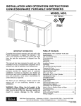
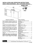
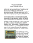
VEND MOTOR WIDE COLUMN
Mounted on the Vender with the Vend Switch on the left side (See Fig. 3). The Linkage and Drive Arm assembly
is used to connect the Vend Motor to the Oscillator. (See Fig. 4)
Vend Motor Switch
804,100,730.01
Nyliner (Rear Stack)
801,803,170.01
Oscillator Assembly
491,070,900.03 - 1¼"
Nyliner (Front Stack)
901,804,230.01
497,071,000.03 - T-Models
Sold Out Spring
#901,700,740.01
Sold-Out Switch Assy. Snap In
#804,100,750.01
(Insulator and Switch are one piece)
Sold-Out Paddle
Wide and Narrow
#432,070,190.13
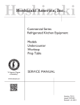
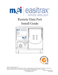
VEND MOTOR NARROW COLUMN
Mounted on the Vender with the Vend Motor Switch on the underside (See Fig. 1). The shaft of the Vend Motor slides
into a slot in the Vend Rotor (See Fig. 2).
Vend Motor Switch
#804,100,730.01
Vend Rotor
#801,201,211.61 - 1¼"
#801,201,220.01 - T Models, Wide
#801,201,230.01 - T Models, Narrow
PRODUCT SHIMMING
Refer to the appropriate technical bulletin for proper set-up and vending procedures. Listed are a few of the more widely
used Technical Bulletins relating to shimming.
Fig. 2
TB 450 Miscellaneous Worldwide Can Shimming, Shimless Stack Series 90
TB 451 Miscellaneous Worldwide Plastic Bottle Shimming, T-Models
TB 452 Miscellaneous Worldwide Non-Returnable Bottle Shimming, T-Models
TB 453 Miscellaneous Worldwide Plastic Bottle Shimming, Shimless Stack Series 90
TB 454 Miscellaneous Worldwide Non-Returnable Bottle Shimming, Shimless Stack Series 90
TB 455 Miscellaneous Worldwide Can Shimming, T-Models
TB 456 Miscellaneous Worldwide Returnable Bottle Shimming, Shimless Stack Series 90
TB 457 Miscellaneous Worldwide Returnable Bottle Shimming, Wide Stack Series 90
TB 473 Miscellaneous Worldwide Non-Returnable Bottle Shimming, Wide Stack Series 90
TB 474 Miscellaneous Worldwide Plastic Bottle Shimming, Wide Stack Series 90
TB 475 Miscellaneous Worldwide Can Shimming, Wide Stack Series 90
TB 476 Miscellaneous Worldwide Returnable Bottle Shimming, T-Models
For shimming of venders or products not listed in the above Technical Bulletins, call the Dixie-Narco Service
Department or contact your Dixie-Narco Representative.
CAMS FOR VEND MOTORS
1.
Adjustable Cam For:
a. DNCB 1¼" deeper wide column.
b. DNCB T-models single, double,
or triple depth wide column.
c. Color of Cam is Gold.
d. Part #801,806,400.11
2.
Vending Cam For:
a. DNCB 1¼" deeper single double depth
wide column.
b. DNCB T-models single depth wide column.
c. Color of Cam is Blue.
d. Part #801,806,390.41
3.
Vending Ca m For:
a. DNCB T-models double
or triple depth wide column.
b. Color of Cam is Green.
c. Part #801,806,410.41
4.
Adjustable Cam For:
a. DNCB 1¼" deeper narrow column.
b. DNCB T-models single, double, or
triple depth narrow column.
c. Color of Cam is Brown.
d. Part #801,806,610.21
5.
Vending Cam For:
a. DNCB 1¼" deeper narrow column.
b. DNCB T-models single, double, or triple depth narrow column.
c. Color of Cam is Brown.
d. Part #801,806,180.21
CAM INSTALLATION AND REMOVAL
TO INSTALL A VENDING CAM:
1. Select the Vending Cam required (See page 39).
2. Locate the Hub at the center of the Cam (See Fig. 6).
3. With the Hub facing you, slowly slide the Cam on the front shaft of the Vend Motor while depressing the
Lock Tab. (See fig. 6).
NOTE:
Reference below for timing of the Motors.
4. A distinct click will be heard, when the tab has locked into the locator hole of the motor shaft.
CAUTION:
Depress the Switch Arm when installing the Cam to prevent possible damage to the Switch Arm.
TO INSTALL AN ADJUSTABLE CAM:
1. Select the Adjustable Cam required. (See page 39).
2. Locate the Lift Tab on the outer edge of the Cam. (See fig. 5).
3. With the Lift Tab facing you, align the slot of the Adjustable Cam with the Locking Tab of the Vending Cam.
4. Place the Adjustable Cam on the Vending Cam.
CAUTION:
5.
Depress the Switch Arm when installing the Cam to prevent possible damage to the Switch
Arm.
Lift the Lock Tab of the Vending Cam, at the same time lift the Lift Tab of the Adjustable Cam and rotate the
Adjustable Cam clockwise to the desired setting.
TO REMOVE AN ADJUSTABLE CAM:
1. Lift the Lift Tab and rotate the Adjustable Cam clockwise until the Vending Cam Lock Tab is aligned with the
slot of the Adjustable Cam.
2. Remove the Adjustable Cam from the shaft of the Motor.
TO REMOVE THE VENDING CAM:
1. Depress (push in) the Lock Tab firmly to disengage it from the Motor shaft.
2. At the same time pull the Vending Cam towards you until it is removed from the Motor shaft.
TIMING
TO SET THE TIMING OF A NARROW COLUMN VEND MOTOR:
1. Make sure the hole through the rear shaft is in a horizontal plane. (If a pin were inserted in the hole, the pin
would be horizontal.) See Fig. 8.
2.
3.
4.
5.
The Vend Rotor must be in the loading position when the Motor shaft is inserted in the end of the Rotor. See
Fig. 8.
Insert the Motor shaft in the Rotor and secure the Motor.
Install the Vending Cam on the front shaft of the Motor making sure the Lock Tab is at the 9 o'clock position.
See Fig 7.
Install the Adjustable Cam per the instructions given on the previous page.
TO SET THE TIMING OF A WIDE COLUMN VEND MOTOR.
1. Make sure the hole through the rear shaft is in a horizontal plane. (If a pin were inserted in the hole, the pin
would be horizontal). See Fig. 10.
2. Slide the Drive Arm (with linkage attached) on the rear shaft as shown. See Fig. 10.
3. Secure by installing the Groove Pin.
4. With the Oscillator in position, align the hole in the Linkage Arm with the pin of the Oscillator.
5. Slide the Linkage on the pin.
6. Install the Vending Cam on the front shaft of the Motor making sure that the Lock Tab is at 6 o'clock as
shown. See Fig. 11.
NOTE:
When the screw holding the Linkage Arm to the Drive Arm is at the 12 o'clock position
(See Fig. 10), the Lock Tab will be at the 6 o'clock position (See Fig. 11).
7. Install the Adjustable Cam per the instructions on page 40.
REAR SPACER
The Rear Spacer, one for each column, is located vertically at the rear of the column. The latch fingers or springs,
adjustable by hand, slide into the holes in the column wall for cans and other package settings.
Note:
Rear Spacers with Springs are not shown.
See Fig. 13, the Latch Fingers are in the open position with the Lock Tabs disengaged.
See Fig. 14, the Latch Fingers are in the closed position with the Lock Tabs engaged. Make sure the tabs are in a locked
position as shown, before loading the Vender.
FOR REFERENCE ONLY
Rear Spacer adjustment holes located in the sidewalls of the stacks.
CLEANING THE VENDER
DO NOT USE A WATER JET OR NOZZLE TO CLEAN THE VENDER.
WHAT TO CLEAN
SIGN FACE
The polycarbonate sign face requires proper cleaning to prolong the service life of this item. It is recommended that you
periodically clean the sign face as follows:
1.
Rinse the sign with a soft cloth or sponge soaked in warm water.
2.
3.
CABINET
1.
2.
3.
4.
WARNING:
If necessary, use a mild soap to loosen any dirt or grime. To prevent damage, DO NOT SCRUB or use a
brush or squeegee, as some signs have a clear ultraviolet resistant coating to prevent yellowing.
Repeat the above steps as necessary, then dry using a soft cloth to prevent spotting.
Wash the cabinet with a good detergent or soap mixed in warm water.
Wax the vender often with a good grade of automobile wax.
Any corrosion inside the vender should be removed with fine steel wool and the area should be painted with
aluminum paint.
Repair any scratches on painted surfaces to prevent corrosion.
THE COMPRESSOR ELECTRICAL CIRCUIT IS ALWAYS LIVE WHEN THE PLUG IS CONNECTED
TO AN ELECTRICAL OUTLET.
REFRIGERATION CONDENSER
Check the condenser periodically for dirt or lint build up.
Remove the build up with a brush or vacuum, or blow the dirt out of the condenser with compressed air and
approved safety nozzle.
3. Ensure nothing obstructs air intake at the bottom of the main door.
4. Ensure nothing obstructs air exhaust at the rear of the cabinet.
1.
2.
COIN ACCEPTOR
Follow the Coin Acceptor Manufacturer's instructions.
LUBRICATING THE VENDER
The vender refrigeration system does not require any field lubrication. The hermetic refrigeration system and fan motors
are manufactured with lifetime lubrication.
Temperature Control Adjustments
Adjustment #1 - Temperature Adjustment
Turn the adjustment clockwise for colder product and counter-clockwise for warmer product. This will change
the cut-out temperature only, the cut-in temperature remains constant.
Adjustment #2 - Altitude Adjustment
WARNING:
DISCONNECT POWER TO THE VENDING MACHINE BEFORE PROCEEDING
WITH THIS ADJUSTMENT.
The control is factory set for an altitude of 152 M (500 ft.). For higher altitudes, adjust the inside range screws to prevent
freeze-up of the product. Adjust the inside range screws as follows.
SIID VENDING
1.
Problem:
Free vend on one column.
Troubleshooting:
A)
Check selection price.
B)
Check for bad connections or broken, backed out, or crossed wires from vend motor to
control board.
C)
Check for sticking select button.
D)
Check control board.
2.
Problem:
One motor continues to home with door closed, shows "COLJ" when "ErOr" routine is entered.
Troubleshooting:
A)
If using Mars Validator, ensure correct interface harness is used.
B)
Check for bad connections or broken, backed out, or crossed wires from vend motor to
control board. (Note: Check wires on left side of vend motor cover.)
C)
Check vend switch.
D)
Check control board.
3.
Problem:
One column sold out, but still vends.
Troubleshooting:
A)
Check sold-out switch.
B)
Check for bad connections or broken, backed out, or crossed wires from sold-out switch
to control board. (Note: Check wires on left side of vend motor cover.)
4.
Problem:
Vender will not sequence (Coca-Cola only).
Troubleshooting:
A)
Ensure wire #24 is in select panel harness and is in correct pin location.
B)
Check for bad connection or broken wire #24 in select panel harness.
C)
Make sure wire #24 is in correct location.
D)
Check control board.
5.
Problem:
Free vend on one or more columns.
Troubleshooting:
A)
Check secondary pricing program.
B)
Check for bad connections or broken, backed out, or crossed wires from vend motor to
control board.
C)
Check for sticking select button.
D)
Check for bad vend motor switch.
E)
Check control board.
6.
Problem:
Column Jackpots.
Troubleshooting:
A)
Check problem column(s) in motor test.
B)
Check motor for:
1. Syrup on brake.
2. Locate/check brake spring.
3. Check motor switch.
C)
Check wiring from/to motor switch of problem column.
D)
Check wiring at mate-n-lock on cabinet harness and cabinet extension harness.
E)
Check motor.
F)
Check control board.
7.
Problem:
Column will not vend.
Troubleshooting:
A)
Go to diagnostics and test.
B)
Check for bad connection or broken, backed out, or crossed wires.
(Also check ballast wires.)
8.
Problem:
Motor stops on high cam.
Troubleshooting:
A)
Change vend switch.
B)
Install current software.
-5 or 380.11 or greater two-button programming.
-3.16 or 390.11 or greater four button programming.
SIID VENDING
9.
Problem:
No motors work.
Troubleshooting:
A)
Check F2 motor power fuse (6 Amp).
B)
Check lamp and lamp wiring for broken, backed out, or crossed wires.
C)
Check ballast and ballast wiring for broken, backed out, or crossed wires.
10. Problem:
F2 motor power fuse continuously blows.
Troubleshooting:
A)
Check if 6 Amp fuse is used.
B)
Check that capacitor instead of MOV used at CR1 location.
C)
Check ohms of each motor in off state
- unplug wires to coil of motor.
- ohms should be 6.5, if less coil of motor has a short.
D)
Check motor harness.
E)
Check motor extension harness.
F)
Check for bad bulb in lighting system.
SIID COIN / CURRENCY
1.
Problem:
Will not accept coins or bills.
Troubleshooting:
A)
Check coin return lever is not pressed.
B)
Check F3 peripheral (1.0 Amp) fuse.
C)
Go to diagnostics and test.
1. Will not take coins, replace coin mech.
2. Still will not take coins, check connections and mech harness.
D)
Check for bad connections or broken, backed out, or crossed wires from
validator/changer to control board.
E)
With Mars 6510 Mdb mechs, serialized 176xxxxxxxx that do not have a red dot on the
coin mech, check the coin mech.
F)
Check control board.
2.
Problem:
Validator sometimes sets up credit and then steals bill.
Troubleshooting:
A)
Check for proper interface harness.
B)
Check for bad connections or broken, backed out, or crossed wires from vend/sold-out
harness.
C)
Check validator.
D)
Check control board.
3.
Problem:
Accepts coins and displays, but will not vend.
Troubleshooting:
A)
Check coin mech.
B)
Check for bad connections or broken, backed out, or crossed wires from
validator/changer to control board.
C)
Check voltage supply (110-115AC) at outlet.
D)
Check control board.
4.
Problem:
Incorrect change paid back, use correct change lamp stays on.
Troubleshooting:
A)
Check control board.
5.
Problem:
Cannot dump coins when in "CPO" mode.
Troubleshooting:
A)
Check for bad connections or broken, backed out, or crossed wires from changer to
control board.
B)
Check select switches and wiring.
C)
Check coin mech.
D)
Ensure you are not using Mars International Executive or NRI Simplex changers.
E)
Check voltage supply (110-115AC) at outlet.
F)
Check control board.
6.
Problem:
BA30 stealing bills.
Troubleshooting:
A)
Check door switch.
B)
Check validator.
C)
Check interface harness.
7.
Problem:
Want to install a debit card system.
Troubleshooting:
A)
Need to contact card system supplier for details.
8.
Problem:
$1 and $5 Bill Acceptance (Black label box 2 button programming)
Troubleshooting:
A)
Works with
1. BA-30
2. VFM-3 Low Level
3. DBA -2 or 3
9.
Problem:
$1 and $5 Bill Acceptance (Red label box 4 button programming)
Troubleshooting:
A)
Works with
1. BA-30 Mdb
2. Mars VN 2500 Series Mdb
SIID COIN / CURRENCY
10. Problem:
Install bill, unplug vender, plug in vender, gives $1 credit and bill back.
Troubleshooting:
A)
Set Escrow to "Pr" or "ES-4"
B)
Install current software.
-5 or 380.11 or greater two-button programming.
-3.16 or 390.11 or greater four-button programming.
11. Problem:
Install Debitek card, unplug vender, plug in vender, jackpots changer.
Troubleshooting:
A)
Install current software (Eprom).
-5 or 380.11 or greater two-button programming.
-3.16 or 390.11 or greater four-button programming.
12. Problem:
After a few vends, the Mars 6510 Mdb disables itself (i.e. stops taking coins).
Troubleshooting:
A)
Install current software (Eprom)
- 804,911,380.41 or greater two-button programming.
- 804,911,390.21 or greater four-button programming.
13. Problem:
New 4-tube changer will not pay out dollar coin.
Troubleshooting:
A)
Install current software (Eprom).
- 380.51 or greater two-button programming.
- 390.11 or greater four-button programming.
14. Problem:
Software does not work with free vend note token in BA30.
Troubleshooting:
A)
Install current software.
- 380.51A or greater two-button programming.
- 390.31 or greater four-button programming.
15. Problem:
Coinco 9302GX changer dispenses all nickels first, then correct change lights come on (sample price
this occurs .60¢).
Troubleshooting:
A)
Load the nickels in coin fill (CD) mode. Note: This is a Coinco 9302GX problem.
SIID SOLD-OUT MESSAGE
1.
Problem:
Sold-out message stays on.
Troubleshooting:
A)
Check limited access program.
B)
Check for crossed wires in cabinet harness and cabinet extension harness or loose wire
harness connection.
C)
Check for motors rubbing motor cover (on early SIID venders).
2.
Problem:
Sold-out message comes on with product in column.
Troubleshooting:
A)
Check programming and ensure limited access is not on.
B)
Check for bad connections or broken, backed out, or crossed wires from select switch to
control board.
(Note: Check wires on left side of motor cover.)
C)
Check for motor rubbing motor cover (on early SIID venders).
3.
Problem:
Sold-out switches work the incorrect column.
Troubleshooting:
A)
Ensure correct cabinet harness and select harness are being used.
B)
Check for crossed wires in cabinet harness or cabinet extension harness.
SIID SELECT PANEL / DISPLAY
1.
Problem:
Plug in vender and displays a blank or "rrrr" appears on the display; vender will not funciton.
Troubleshooting:
A)
Press a select button to change message on display; this should clear "RRRR"s.
B)
Remove power to vender for one minute, then power vender back up.
C)
Check main power plug for loose connection.
D)
Check for bad connections or broken wires from display to control board.
E)
Check display board.
F)
Check control board.
2.
Problem:
Display will not function.
Troubleshooting:
A)
Check for bad connections or broken wires from display to control board.
B)
Check F1 motor power fuse (1.6 Amp).
C)
Check display board.
D)
Check transformer.
E)
Check control board.
3.
Problem:
Display shows $1 and then increases in dollar increments.
Troubleshooting:
A)
Check coin mech.
B)
Check validator.
C)
Check control board.
4.
Problem:
Cannot set price on a given selection.
Troubleshooting:
A)
Check configuration 1 is set to C1 1 (multi-pricing).
B)
Check for bad connections or broken wires from select switch to control board.
C)
Check select switches.
D)
Check control board.
5.
Problem:
6.
Problem:
Control board looses its memory when power is shut off to vender.
Troubleshooting:
A)
Check battery (see problem 16 on next page).
B)
Check control board.
7.
Problem:
Space to sales does not work properly when adding and deleting columns.
Troubleshooting:
A)
Check for bad connections or broken wires from select switch to control board.
B)
Check control board.
8.
Problem:
F2 motor power fuse (6 Amp) blows when a given motor runs.
Troubleshooting:
A)
Check motor for short.
B)
Check motor switch and motor wires for short.
C)
Check motor.
D)
Check the ballast, lamps, and lamp harnessing for broken, backed out, or crossed wires.
9.
Problem:
Board power fuse blows when supplying power.
Troubleshooting:
A)
Check changer and interface harness.
B)
Check validator and interface harness.
Vender changes a set vend price to .10¢ on selections on its own. (domestic only - .10¢ could be any
given price.)
Troubleshooting:
A)
Check secondary pricing program.
B)
Check for bad connections or broken wires from select switch to control board.
C)
Check control board. (Possible cold solder joints.)
10. Problem:
Flashing decimal point.
Troubleshooting:
A)
Go to diagnostics.
• All columns shown to be jammed.
• Check 6 Amp motor fuse (F2).
• Select problem.
• Enable problem (check board).
• Pb problem (check board).
SIID SELECT PANEL / DISPLAY
11. Problem:
Plug in vender and "1-1-1-1" scrolls across display.
Troubleshooting:
A)
Remove power to vender for one minute, then power vender back up.
B)
Check for bad connections or broken, backed out, or crossed wires in select panel
harness.
C)
Check top of door weld assembly for seal.
D)
Check control board.
12. Problem:
Display shows "LOC".
Troubleshooting:
A)
Can only be accessed via DEX or hand-held.
B)
Check control board.
13. Problem:
Will not show vend price on display.
Troubleshooting:
A) All vend prices on primary price have to be the same price, and all prices on secondary
price have to be the same price.
14. Problem:
When programming, the display takes 30 to 45 seconds to go from one program to another.
Troubleshooting:
A)
Unplug the coin mech and then program the SIID control box.
15. Problem:
Display goes blank when you press a given select button.
Troubleshooting:
A)
Check for bad vend motor on selection pressed. (Wire broken at coil or possible spade
pulled out)
16. Problem:
Set price, unplug vender, plug in vender and price changes to 99.95.
Troubleshooting:
A)
Check battery. Follow steps to check.
1. Unplug vender.
2. On Ardac boards, locate component LH5168D-10L at U6 on board.
On DeAmertek boards, locate component LH5168D-10L at U2 on board.
3. Set volt meter to test DC voltage.
4. Put one test lead on pin 14.
5. Put other test lead on pin 28.
6. Volt meter should read minimum 2 VDC.
7. If bad battery (under 2 VDC), replace the board.
17. Problem:
All segments
Troubleshooting:
A)
B)
C)
stay illuminated on display.
Toggle to proper setting (14 segment versus 7 segment).
Connector harness loose at display board.
Check for bad connection or broken, backed out, or crossed wires is display harness.
18. Problem:
Plug in vender and "1-1-1-1" scrolls across the display. Press the service switch and "EN#" is
displayed.
Troubleshooting:
A)
Check control board.
REFRIGERATION PARTS AND FUNCTIONS
- MECHANICAL PARTS COMPRESSOR MOTOR
The compressor motor (sealed in the compressor housing) drives the compressor with a shaft that is shared by
both parts. It is started by the temperature control switch and the starting relay. It is stopped by the temperature
control switch, and, if it gets overloaded, by the thermal overload switch.
COMPRESSOR
The compressor (sealed in the compressor housing) draws cold, low pressure refrigerant gas from the
evaporator and pumps hot, high pressure refrigerant gas out to the condenser.
CONDENSER
The condenser, located in the base of the vender, at the front, takes heat out of the hot, high pressure gas that
comes from the compressor. The gas loses heat as it goes through the condenser coils, and changes into a
liquid because it is still under pressure.
CONDENSER FAN
The condenser fan (between the condenser and the compressor motor), first draws air from the outside of the
vender through the condenser. This air takes heat from the condenser first and then is blown over the
compressor housing from which it also takes heat before going back outside of the vender. The condenser fan
runs when the compressor motor runs.
FILTER/DRYER
The filter/dryer is in the liquid line between the condenser and the capillary tube. This dryer filters out any foreign
particulate matter and also contains a desiccant to absorb any moisture that may be present in the system.
CAPILLARY TUBE
The capillary tube (between the condenser and the evaporator in the refrigerant line) has a very small inside
diameter, and serves to control the refrigerant flow from the condenser into the evaporator.
EVAPORATOR
The evaporator (in the vender cabinet) takes heat from the air in the vender cabinet and gives this heat to the
liquid refrigerant. The liquid refrigerant is evaporated (boiled off) as a gas, and the gas is drawn out by the
compressor.
EVAPORATOR FAN
The evaporator fan draws warm air from around the cans or bottles in the cooling compartment and blows it
across the evaporator. As the air goes across the evaporator, it gives up heat to the evaporator, then goes back
to the cans or bottles, and takes heat from them. This fan runs continuously when the vender is plugged in.
CONDENSATE PAN
The condensate pan (located in the compressor compartment) collects the water which runs from the
evaporator. The water is evaporated into the surrounding air by means of soakers. The soakers extend down
into the pan to absorb the water. Exposure to the surrounding air evaporates the water in the soakers.
- ELECTRICAL PARTS TEMPERATURE CONTROL
The temperature control is the part that is made up of a control bulb connected by a small metal tube to a
bellows. The control bulb is in a slot in the evaporator fan housing. The bellows and a switch known as the
temperature control switch, are in the temperature control box which is fastened to the right side ins ide the
vender.
The control bulb and the bellows have a vapor in them. When the temperature of the vapor in the bulb rises, it
builds up pressure in the bellows tube. This pushes the bellows out. When the control bulb is cool, the vapor
shrinks back, and the bellows pulls in. These movements, of the bellows, work the switch - called the
temperature control switch - closing it when the bulb is heated and opening it when the bulb is cooled.
The contacts of the temperature control switch are in the compressor motor's running and starting circuits. They
are also in the condenser fan motor circuit.
When the cabinet temperature gets up to the cut-in setting, the temperature control switch closes in the
compressor motor's starting and running circuits and in the condenser fan circuit. When the cabinet temperature
gets down to the cut -out setting, the temperature control switch opens in these circuits.
CAUTION:
To adjust the temperature control see page 44.
THERMAL OVERLOAD ASSEMBLY
The thermal overload is a temperature activated switch that interrupts power to the compressor when excessive
temperatures occur. This switch protects the compressor from the damage that will occur if the compressor
continues to operate under adverse conditions. The overload also opens under abnormally high amp draws,
protecting the motor windings from damage. Frequent overload trips may lead to warm product and be the first
indication of a dirty condenser or other refrigeration related problems that require attention.
STARTING RELAY
The starting relay is a device that connects the start winding of the compressor during start up. The additional
winding (start) helps the compressor motor come up to speed. Once it reaches speed the starting relay
disconnects the start winding from the circuit.
GLOSSARY
1.
DEX
Direct Exchange of Data
2.
"Dixie Bus"
Dixie-Narco Serial Communication Specification to allow Dixie-Narco to add extra
features without affecting current vender designs.
3.
IR
Infrared
4.
LCD
Liquid Crystal Diodes
5.
LED
Light Emitting Diodes
6.
MDB
Multi-Drop Bus
7.
NAMA
National Automatic Merchandising Association
8.
UCS
Uniform Communications Standards
9.
UCC
Uniform Code Council
Coca-Cola Serial Communication Specifications. Used in all
Dixie SIID can venders.
COCA-COLA MARKETING MACHINE SERVICE MANUAL
DIXIE-NARCO, INC.
TABLE OF CONTENTS
Main Door Exterior................................................................................................................ Page 4
Main Door Interior ................................................................................................................. Page 7
Pull Out Handle & Coin Insert ...........................................................................................Page 10
Select Panel / Coin Insert Panel.......................................................................................Page 12
Lighting .................................................................................................................................Page 15
Wiring Harness....................................................................................................................Page 16
Inner Door ............................................................................................................................Page 18
Two-Bar Linkage / Nut Re tainer Housing .......................................................................Page 20
Hinges and Roller Assy. ....................................................................................................Page 21
Cabinet Interior..................................................................................................................Pages 24
Cabinet and Vend Mechanism........................................................................................Pages 27
Refrigeration System ........................................................................................................Pages 31
Electronic Components ......................................................................................................Page 35
Screws and Nuts .................................................................................................................Page 38
Washers, Bolts, & Miscellaneous Hardware ................................................................Pages 40
COCA-COLA MARKETING MACHINE SERVICE MANUAL
DIXIE-NARCO, INC.
COCA-COLA MARKETING MACHINE SERVICE MANUAL
DIXIE-NARCO, INC.
MAIN DOOR EXTERIOR
ITEM #
1
2
3
4
5
6
7A
7B
DESCRIPTION
Coke Marketing Machine, Door Assy.
72" Wide -13 S3D
72" Narrow -13 S3D
79" Wide -13 S3D
72" Wide -9 S2D
72" Narrow -9 S2D
79" Wide -9 S2D
Coke Marketing Machine, Door Weld Assy.
72" Wide
72" Narrow
79" Wide
Protective Plate Door
72" Wide / Narrow
79"
Rain Guard
72" and 79" Wide
72" Narrow
Horizontal Trim
Bottom, Wide
Bottom, Narrow
Control Panel, Wide
Control Panel, Narrow
Vertical Trim
Left and Right
Center
Hinged Top Sign Trim Assy.
72W, 72N, 79W
Top Sign Trim Locking Bar
PART NUMBER
624,053,30x.x3
624,053,50x.x3
624,053,00x.x3
624,053,20x.x3
624,053,40x.x3
624,053,10x.x3
624,050,10x.x3
624,050,20x.x3
624,050,00x.x3
165,150,33x.x3
164,150,33x.x3
164,151,14x.x3
169,050,34x.x3
801,810,65x.x1
801,810,65x.x1
801,810,65x.x1
801,810,65x.x1
801,810,63x.x1
801,810,64x.x1
801,810,66x.x1
801,810,86x.x1
7C
Assy., Bracket Sign Trim Cap
8
W/A Port Trim Spacer
624,052,20x.x3
624,052,40x.x3
8A
Port Trim
8B
Port Spacer
9
Sign (Full Length)
72" Wide Bottle Domestic
72" Narrow Bottle Domestic
79" Wide Bottle Domestic
72" Wide Can Domestic
72" Narrow Can Domestic
79" Wide Can Domestic
72" Narrow Can Export
72" Narrow Bottle Export
805,700,95x.x1
805,700,67x.x1
805,025,06x.x1
805,025,07x.x1
805,025,05x.x1
805,025,44x.x1
805,025,45x.x1
805,025,43x.x1
805,026,52x.x1
805,026,53x.x1
COCA-COLA MARKETING MACHINE SERVICE MANUAL
ITEM #
10
11
12
13
DESCRIPTION
Advertise Window
72" Wide and 72" Narrow
79" Wide
Port Panel
Wide / Narrow
Hinges, Main Door
Assy, Top
Assy, Bottom
Advertise Window Card
DIXIE-NARCO, INC.
PART NUMBER
805,025,32x.x1
805,025,31x.x1
624,050,53x.x3
624,052,90x.x3
801,305,13x.x1
803,853,88x.x1
14
15
Decal, Port Panel
72W
Decals
Right Side Door 72"
Right Side Door 79"
Left Side Door 72"
Left Side Door 79"
Vandal Panel Door 72"
Vandal Panel Door 79"
Protective Plate Left Side Cabinet 72"
Protective Plate Left Side Cabinet 79"
Protective Plate Right Side Cabinet 72"
Protective Plate Right Side Cabinet 79"
803,854,42x.x1
803,853,89x.x1
803,853,92x.x1
803,853,91x.x1
803,853,93x.x1
803,853,94x.x1
803,853,95x.x1
803,853,96x.x1
803,853,97x.x1
803,853,98x.x1
803,853,99x.x1
A4
Screw, Phil Pan w/out Washer #8-18x½"
900,301,50x.x1
B2
B3
B7
B10
Keps Nut ¼-20
Keps Nut #8-32
Elastic Stop Nut #8-32
Hex Nut, Center w/ Flange 5/1 6-18 (top hinge - drop in)
900,800,67x.x1
900,800,50x.x1
900,800,51x.x1
900,801,02x.x1
D2
D3
D4
T-Bolt #8-32x1 3/8"
T-Bolt #8-32x¾"
T-Bolt #8-32x½"
900,400,41x.x1
900,400,35x.x1
900,400,45x.x1
E4
E8
Carriage Bolt ¼-20x½"
Carriage Bolt 5/16-18x1-¼ (top hinge - drop in)
900,201,45x.x1
900,201,85x.x1
F5
Pop Rivet, Steel (Zinc Plated) 1/8"
901,100,61x.x1
H1
Christmas Tree Clip, #354280307-00
900,902,13x.x1
COCA-COLA MARKETING MACHINE SERVICE MANUAL
DIXIE-NARCO, INC.
COCA-COLA MARKETING MACHINE SERVICE MANUAL
DIXIE-NARCO, INC.
MAIN DOOR INTERIOR
ITEM #
1
DESCRIPTION
PART NUMBER
Delivery Port (Large Port)
801,810,68x.x1
2
8
Delivery Port Spacer (Large Port)
W/A Trim Spacer
Right Side
Left Side
Port Stiffener
Wide / Narrow
Access Door (prior to 6506AX)
Wide / Narrow
Access Door (hinged) (0001-6506AX and higher)
Wide / Narrow
Hopper
Top
Door Rod
Wide
Narrow
Door Hinge
Top
Bottom
Cash Box W/A
9
Cash Box Coin Chute Assy.
10
Cash Box Shelf
Wide
Closure Strip
Wide / Narrow
Cover, Wire Plug
Wide / Narrow
"L" Profile Gasket
Wide
Narrow
Assy., Coin Return Cup
Wide / Narrow
Weld Assy. Coin Return Cup
Wide
Coin Return Cup Door
3
4A
4B
5
6
7
624,052,40x.x3
624,050,64x.x3
624,050,63x.x3
624,050,03x.x3
805,700,89x.x1
805,701,12x.x1
805,700,69x.x1
801,401,83x.x1
801,401,84x.x1
801,305,14x.x1
801,305,13x.x1
624,052,80x.x3
624,052,70x.x3
11
12
13
14
15A
15B
805,700,66x.x1
609,050,14x.x3
624,050,67x.x3
903,600,53x.x1
903,600,54x.x1
624,052,30x.x3
624,050,30x.x3
801,810,75x.x1
16
17
18
19
Lamp Bracket
Wide / Narrow
S3D Mounting Bracket
72" Wide / Narrow
79" Wide
Bracket, Door Switch
Wide / Narrow
Bill Validator Guard
Wide / Narrow
624,050,39x.x3
624,050,72x.x3
624,050,73x.x3
604,051,28x.x3
805,700,98x.x1
COCA-COLA MARKETING MACHINE SERVICE MANUAL
ITEM #
20
21
22
DESCRIPTION
Access Door Anti Vandal Bracket
Wide
Access Door Jamb
Wide / Narrow (prior to 6506AX)
Wide / Narrow (0001-6506AX and higher)
Coin Chute Bracket
DIXIE-NARCO, INC.
PART NUMBER
805,701,02x.x1
805,700,97x.x1
805,701,09x.x1
805,701,01x.x1
23
24
Standoff
.192x.312x.312
Push Nut, Acorn Type
901,001,46x.x1
900,902,37x.x1
25
Hopper Strap
26
Access Door Hinge (0001-6506AX and higher)
Top
Bottom
Access Door Latch
0001-6506AX and higher
624,050,79x.x1
27
624,054,10x.x3
624,054,20x.x3
801,304,53x.x1
A4
A5
A9
A11
A15
A16
A20
Screw, Phil Pan w/out washer #8-18x½"
Screw, Phil Pan Swage Form #8-32x3/8"
Screw, Phil Pan Swage Form #8-32x3/8" (prior to 1970-6462)
Screw, Phil Pan Sems #8-32x¼" (s/n 1970-6462 & higher)
Screw, Machine Truss #10-32x½"
Screw, Phil Pan Sems w/washer #8-18x½"
Screw, Machine Phil Pan #8-32x¾"
900,301,50x.x1
900,301,80x.x1
900,301,56x.x1
900,301,97x.x1
900,201,14x.x1
900,301,65x.x1
900,201,22x.x1
B1
B2
B3
B7
Keps Nut #10-32
Keps Nut #¼-20
Keps Nut #8-32
Elastic Stop Nut #8-32
900,800,65x.x1
900,800,67x.x1
900,800,50x.x1
900,800,51x.x1
C12
Nylon Spacer (prior to 1970-6462)
801,902,48x.x1
E2
E4
E5
Carriage Bolt ¼x20x1
Carriage Bolt ¼-20x½
Carriage Bolt ¼-20x3/8"
Carriage Bolt ¼-20x½ Red
900,201,17x.x1
900,201,45x.x1
900,201,54x.x1
900,202,04x.x1
F5
Pop Rivet, Steel (Zinc Plated) 1/8"
901,100,61x.x1
I2
Nylon Spacer
801,902,48x.x1
COCA-COLA MARKETING MACHINE SERVICE MANUAL
DIXIE-NARCO, INC.
COCA-COLA MARKETING MACHINE SERVICE MANUAL
DIXIE-NARCO, INC.
PULL OUT HANDLE & COIN INSERT
ITEM #
1A
Assy. T-handle
DESCRIPTION
1B
T-Handle Flange
1C
T-Handle Only
1D
T-Handle Stud
PART NUMBER
801,518,20x.x1
801,518,18x.x1
801,518,14x.x1
801,518,17x.x1
2
Coin Chute Assy.
3A
Coin Return Assy.
624,052,60x.x3
624,052,50x.x3
3B
Push Button Coin Return
3C
Coin Return Button Bracket
801,807,25x.x1
624,050,23x.x3
3D
3F
Bushing
.500x.625
Coin Return Rocker
#6 (serial break not available at print)
#8 (first 10,000 venders - s/n 0001-6501BW to ####-####)
Roller Pin
3G
Roller Pin Retainer
3H
3I
Coin Return Cable Assy.
#6 Cable (serial break not available at print)
#8 Cable (first 10,000 venders - s/n 0001-6501BW to ####-####)
Coin Return Changer Bracket
3J
Coin Return Changer Rocker
3K
Coin Return Spring
3L
4
Wing Nut
6-32 (serial break not available at print)
8-32 (first 10,000 venders - s/n 0001-6501BW to ####-####)
Coin Chute Bracket
5A
Display Lens
5B
Display Lens Gasket
3E
801,903,13x.x1
805,700,61x.x1
805,700,56x.x1
900,502,19x.x1
900,900,90x.x1
801,305,15x.x1
801,305,17x.x1
624,050,21x.x3
624,050,45x.x3
901,701,07x.x1
800,801,14x.x1
800,801,15x.x1
805,701,01x.x1
801,810,67x.x1
802,001,28x.x1
6
7
Coin Insert Label
S3D
SIID
Coin Chute Can Diverter
803,853,85x.x1
803,853,83x.x1
805,701,11x.x1
COCA-COLA MARKETING MACHINE SERVICE MANUAL
COIN INSERT PANEL
SELECT PANEL
DIXIE-NARCO, INC.
COCA-COLA MARKETING MACHINE SERVICE MANUAL
DIXIE-NARCO, INC.
SELECT PANEL / COIN INSERT PANEL
ITEM #
1A
1B
2
DESCRIPTION
Select Panel Assy.
12 Select
8 Select
Select Panel Stud Assy.
12 Select
8 Select
Select Button
PART NUMBER
624,051,80x.x3
624,051,90x.x3
624,052,00x.x3
624,052,10x.x3
801,810,62x.x1
3
5
Select Button Retainer
.063x1 9/ 16x14 13/16
Select Button Stop
.063x2.301x14.813
Select Switch SIID
6
Switch Insulator
4
624,050,12x.x3
805,700,58x.x1
804,100,74x.x1
801,805,92x.x1
7A
8A
Coin Insert Panel Weld Assembly
Domestic
Export
Coin Insert Panel Stud Assembly
Domestic
Export
POS Window Lens
8B
POS Window Gasket
7B
624,053,90x.x3
624,054,00x.x3
624,051,30x.x3
624,051,40x.x3
801,810,69x.x1
802,001,29x.x1
8C
10A
POS Window Backup Plate
.045x5.422x13.332
Coin Insert POS Card
Thirsty
Feature Button
Retainer, Feature Button
Stop, Feature Button
Mars Validator Mounting Plate
Filler Plate
Feature Button Assy.
Feature Button Plate Assy.
Display Lens
10B
Display Lens Gasket
10C
Display Visibility Gasket
8D
9
624,050,48x.x3
803,853,87x.x1
805,700,93x.x1
805,700,94x.x1
624,050,56x.x3
624,050,57x.x3
624,051,50x.x3
624,051,60x.x3
801,810,67x.x1
802,001,28x.x1
802,001,31x.x1
11A
Validator Filler Plate
360,050,72x.x3
COCA-COLA MARKETING MACHINE SERVICE MANUAL
ITEM #
11B
DESCRIPTION
DIXIE-NARCO, INC.
PART NUMBER
Validator Filler Plate Gasket
902,001,02x.x1
11C
Spacer, Bill Validator
12
Coin Insert Label S3D
624,050,84x.x3
803,853,85x.x1
A6
Screw, Phil Pan #4-24x¾
900,300,47x.x1
B2
B3
Keps Nut ¼-20
Keps Nut 8-32
900,800,67x.x1
900,800,50x.x1
COCA-COLA MARKETING MACHINE SERVICE MANUAL
DIXIE-NARCO, INC.
COCA-COLA MARKETING MACHINE SERVICE MANUAL
DIXIE-NARCO, INC.
LIGHTING
ITEM #
DESCRIPTION
1
Fluorescent Bulb
1A F64T12/D H/O (72")
F72T12/D H/O (79")
1B F42T12D H/O (72")
F48T H/O (79")
1C 48" T8 Metric Philips TLD 36W/840 NG (export)
60" T8 Metric Philips TLD 58W/840 NG (export)
72" T8 Metric Philips TLD 70W/840 NG (export)
2
Door Bracket, Lamp Socket
110V (.045 x 2.684 x 2.985) - 4 per
220 / 50 (.045 x 3.043 x 2.289) - 3 per
220 / 50 79" Bulkhead Socket Bracket (.045 x 2.061 x 3.491) - 1 per
3
Lampholder, Top
H/O 523
4
Lampholder, Bottom
H/O 524
T8 (220 / 50) - 4 per (Leviton 13351-UN)
5
Light Harness, Plug In
H/O
220 / 50 Light Harness
6
Ballast
High Output 110V/60Hz (domestic)
High Output 220 / 240V, 50 / 60 Hz (export)
7
Jumper, H/O Lamp Fixture 22"
Bottom 110V/60Hz (domestic) 22"
220 / 50 Lamp Fixture 24"
8
Boot, Lamp
PART NUMBER
804,700,37x.x1
804,700,36x.x1
804,700,64x.x1
804,700,39x.x1
804,700,66x.x1
804,700,67x.x1
804,700,68x.x1
624,050,39x.x3
624,000,04x.x3
624,050,92x.x3
804,901,99x.x1
804,902,00x.x1
804,917,16x.x1
804,916,02x.x1
804,917,14x.x1
804,400,38x.x1
804,400,55x.x1
804,913,93x.x1
804,916,06x.x1
902,001,21x.x1
9
Lamp Socket Shield
10
220 V (International) Ballast Jumper
A1
Screw, Phil Pan Swage Form #6-32x3/8
624,050,83x.x3
804,917,15x.x1
900,301,70x.x1
COCA-COLA MARKETING MACHINE SERVICE MANUAL
DIXIE-NARCO, INC.
WIRING HARNESS
ITEM #
1
2
3
4
5
6
7
8
9
DESCRIPTION
Cabinet Harness
SIID-9 (Cam and Sold-Out Switch Harness)
SIID-7
Door Harness
CC-9 Electronic
CC-10 Electronic
CC-11, 12, 13 Electronic without Sold-Out Lights
CC 11,12, 13 Electronic with sold out lights
Display Harness
41" SIID / S3D
Coin Mech Harness
MDB
Cabinet Extension Harness
80" SIID / S3D
Motor Extension Harness
76" SIID / S3D
90" SIID / S3D
Motor Harness
SIID-9
SIID-7
DEX Harness
External
Sold-Out Light Harness 9 Select
PART NUMBER
804,915,04x.x1
804,917,01x.x1
804,914,04x.x1
804,913,89x.x1
804,913,92x.x1
804,916,07x.x1
804,909,50x.x1
804,909,78x.x1
804,913,96x.x1
804,913,95x.x1
804,909,29x.x1
804,915,03x.x1
804,917,02x.x1
804,913,97x.x1
804,916,09x.x1
COCA-COLA MARKETING MACHINE SERVICE MANUAL
DIXIE-NARCO, INC.
COCA-COLA MARKETING MACHINE SERVICE MANUAL
DIXIE-NARCO, INC.
COCA-COLA MARKETING MACHINE SERVICE MANUAL
DIXIE-NARCO, INC.
INNER DOOR
ITEM #
1
DESCRIPTION
3
Inner Door Assy.
79" Wide
72" Wide
72" Narrow
Inner Door Gasket
79" Wide
72" Wide
72" Narrow
Knob
4A
Discharge Frame Assy.
4B
Discharge Frame Retainer
2
PART NUMBER
624,051,00x.x3
624,051,10x.x3
624,051,20x.x3
801,804,07x.x1
801,804,06x.x1
801,804,03x.x1
901,501,70x.x1
801,809,16x.x1
801,809,15x.x1
5A
Inner Door Top Hinge Assy.
5B
Inner Door Bottom Hinge Assy.
169,053,00x.x3
169,051,10x.x3
5C
Plastic Bearing
6A
Bushing, Inner Door
6B
Bushing Retainer, Inner Door
901,803,71x.x1
801,806,42x.x1
801,806,43x.x1
A4
A15
A16
A34
Screw, Phil Pan w/out Washer #8-18x½
Screw, Machine Truss #10-32x½
Screw, Phil Pan Sems #8-18x½
Screw, Phil Pan #6-20x3/8
900,301,50x.x1
900,201,14x.x1
900,301,65x.x1
800,303,22x.x1
B1
Keps Nut #10-32
900,800,65x.x1
E3
Carriage Bolt, ¼-20x1¼
900,201,23x.x1
COCA-COLA MARKETING MACHINE SERVICE MANUAL
DIXIE-NARCO, INC.
COCA-COLA MARKETING MACHINE SERVICE MANUAL
DIXIE-NARCO, INC.
TWO-BAR LINKAGE / NUT RETAINER HOUSING
ITEM
1
2A
2B
3
4A
4B
5A
5B
5C
5D
DESCRIPTION
Linkage and Drive Arm Assy.
All Styles
Groove Pin, 1/8x1 3/16 (30mm) - T2
All Styles
Drive Arm (Zinc)
All Styles
Linkage Arm (Zinc)
All Styles
Nyliner, Top
All Styles
Nyliner, Bottom
All Styles
Assy., Nut Retainer Housing "E" - 1 point lock
Coke
Traditional Nut Retainer Housing - 1 point lock
Coke
Cage Nut Traditional - 1 point lock
Coke
Square Nut, 1/2-13 N.C. - 1 point lock
All Styles Standard
All Styles High Security
DNCB 600E
79" Wide
DNCB 501E
72" Wide
DNCB 276E
72" Narrow
NA
NA
NA
900,901,94x.x1
900,901,94x.x1
NA
801,200,95x.x1
801,200,95x.x1
NA
801,201,59x.x1
801,201,59x.x1
NA
901,803,16x.x1
901,803,16x.x1
NA
901,804,77x.x1
901,804,77x.x1
NA
432,052,50x.x4
432,052,50x.x4
432,052,50x.x4
432,050,73x.x3
432,050,73x.x3
432,050,73x.x3
801,803,85x.x1
801,803,85x.x1
801,803,85x.x1
900,800,57x.x1
900,801,06x.x1
900,800,57x.x1
900,801,06x.x1
900,800,57x.x1
900,801,06x.x1
A2
A5
A11
A17
Screw, Phil Pan Swage Form #8-32x1/2"
Screw, Phil Pan Swage Form #8-32x1/4"
Screw, Phil Pan Sems #8-32x1/4"
Screw, Type F, 1/4-20x5/8
900,301,64x.x1
900,301,97x.x1
900,301,97x.x1
900,302,01x.x1
C1
Flat Washer B, Delrin .040 thick 3/8"IDx5/8"OD
900,700,60x.x1
COCA-COLA MARKETING MACHINE SERVICE MANUAL
DIXIE-NARCO, INC.
HINGES AND ROLLER ASSY.
ITEM
1A
DESCRIPTION
2A
Roller, Main Door
All Styles
Roller Pin
All Styles
Assy., Top Hinge (drop in pin) E-Models All Styles
2B
Top Hinge (drop in pin) E-Models All Styles
2C
Top Hinge Spacer
All Styles
Hinge Bearing
All Styles
Bottom Hinge Sleeve
All Styles
Bottom Hinge Pin
1B
2D
3A
3B
3C
DNCB 600E
79" Wide
DNCB 501E
72" Wide
901,806,20x.x1
901,806,20x.x1
900,502,19x.x1
900,502,19x.x1
624,052,90x.x3
624,052,90x.x3
801,305,14x.x1
801,305,14x.x1
169,000,15x.x3
169,000,15x.x3
805,300,42x.x1
805,300,42x.x1
900,502,64x.x1
900,502,64x.x1
900,502,70x.x1
900,502,70x.x1
801,305,13x.x1
801,305,13x.x1
Bottom Hinge
A9
A15
A17
Screw, Phil Pan Swage Form #8-32x3/8"
Screw, Machine Truss #10-32x1/2"
Screw, Self Tapping 1/4-20x5/8"
900,301,56x.x1
900,201,14x.x1
900,302,01x.x1
B2
B4
B10
Keps Nut, 1/4-20
Keps Nut, Top Door Hinge 3/8-16
Hex Nut, 5/16-28 Center w/Flange (top hinge - drop in)
900,800,67x.x1
900,800,69x.x1
900,801,02x.x1
C2
C10
C11
Flat Washer Door Hinge
Washer, Flat 18 Gauge
Flat Washer, 14 Gauge 5/16"-3/8"x7/8"
901,303,77x.x1
900,700,83x.x1
900,700,08x.x1
E2
E6
E8
E9
Carriage Bolt, 1/4-20x1
Carriage Bolt 1/4-20x3/4"
Carriage Bolt, 1/4-20x1 1/4 (top hinge - drop in)
Carriage Bolt, 1/4-20x5/8"
900,201,17x.x1
900,201,56x.x1
900,201,85x.x1
800,303,19x.x1
H5
Retainer, Roller Pin
900,900,90x.x1
COCA-COLA MARKETING MACHINE SERVICE MANUAL
DIXIE-NARCO, INC.
COCA-COLA MARKETING MACHINE SERVICE MANUAL
DIXIE-NARCO, INC.
COCA-COLA MARKETING MACHINE SERVICE MANUAL
DIXIE-NARCO, INC.
COCA-COLA MARKETING MACHINE SERVICE MANUAL
DIXIE-NARCO, INC.
CABINET INTERIOR
ITEM
1
2A
2B
3A
3B
3C
4
5A
5B
5C
5D
5E
6A
6B
7A
7B
7C
8
9
10
DESCRIPTION
Foam Cabinet Assy.
All Styles
Stack Assy.
Single Price - Cans
SIID - Cans
Single Price - Bottles
SIID - Bottles
Stack Assy. Single Price - No Shimming
Stack Assy. SIID - No Shimming
Single Price -330 ml Can 4 deep
SIID -330 ml Can 4 deep
Stack Sub Assy.
All Styles
330 ml Can 4 Deep Single Price
Rear Spacer Assy. Wide Column
All Styles
Rear Spacer Assy. Narrow Column
All Styles
Latch Spring
Wide
Narrow
Protective Plate Left Side
All Styles
Gate, Wire
All Styles
Wire Gate Latch Lock & Guide
All Styles
Wire Gate Bracket Top
All Styles
Gate Label - Caution "E"
All Styles
Clamp, Nylon Cable 1/2"
All Styles
Mullion
All Styles
Mullion Cover
All Styles
Breaker Strip Right
All Styles
Breaker Strip Left
All Styles
Breaker Strip Top
All Styles
Leveling Leg 5/8"-11x2 1/16"
All Styles
Mounting Bracket, Rear
All Styles
Cabinet Front Stiffener Plate
All Styles
DNCB 600E
79" Wide
DNCB 501E
72" Wide
DNCB 276E
72" Narrow
624,000,50x.x3
624,000,30x.x2
624,000,10x.x3
610,070,30x.x3
610,070,50x.x3
610,070,70x.x3
610,070,80x.x3
NA
NA
610,071,60x.x3
610,071,70x.x3
609,071,00x.x3
609,071,20x.x3
609,071,40x.x3
609,071,50x.x3
NA
NA
609,074,30x.x3
609,074,40x.x3
NA
NA
NA
NA
615,070,40x.x3
615,070,00x.x3
609,074,80x.x3
609,074,90x.x3
610,070,40x.x3
610,071,80x.x3
609,071,10x.x3
609,074,50x.x3
615,070,10x.x3
609,075,00x.x3
497,073,10x.x3
498,071,30x.x3
NA
497,073,20x.x3
498,071,40x.x3
498,071,40x.x3
901,700,88x.x1
901,700,86x.x1
901,700,88x.x1
901,700,86x.x1
NA
901,700,86x.x1
594,020,17x.x3
594,020,14x.x3
594,020,14x.x3
801,401,73x.x1
801,401,72x.x1
801,401,76x.x1
801,401,77x.x1
801,401,77x.x1
801,401,77x.x1
609,070,36x.x3
609,070,36x.x3
609,070,36x.x3
803,855,82x.x1
803,855,82x.x1
803,855,82x.x1
900,901,80x.x1
900,901,80x.x1
900,901,80x.x1
801,810,56x.x1
801,810,56x.x1
801,810,85x.x1
801,303,83x.x1
801,303,83x.x1
801,303,83x.x1
491,020,15x.x3
492,020,04x.x3
492,020,04x.x3
491,020,16x.x3
492,020,05x.x3
492,020,05x.x3
491,020,17x.x3
491,020,17x.x3
493,020,06x.x3
900,502,49x.x1
900,502,49x.x1
900,502,49x.x1
609,070,24x.x3
609,070,24x.x3
609,070,24x.x3
594,021,10x.x3
594,021,10x.x3
596,020,20x.x3
COCA-COLA MARKETING MACHINE SERVICE MANUAL
ITEM
11
DESCRIPTION
DIXIE-NARCO, INC.
DNCB 600E
79" Wide
DNCB 501E
72" Wide
DNCB 276E
72" Narrow
801,807,10x.x1
801,807,10x.x1
801,807,10x.x1
801,809,93x.x1
801,809,93x.x1
801,809,93x.x1
801,903,34x.x1
801,903,34x.x1
801,903,34x.x1
164,000,04x.x3
165,000,04x.x3
15
Trim Access Hole Stiffener
All Styles
Caterpillar Grommeting
All Styles
Kydex Door
All Styles
Protective Plate Right, Cabinet
A4
A5
A9
A10
A14
A16
A17
A19
A21
A26
Screw, Phil Pan 8-18x1/2
Screw, Phil Pan Swage Form #8-32x1/4"
Screw, Phil Pan 8-32x3/8
Screw, Machine #6-32x1 1/4"
Screw, Phil Pan 10-32x1 1/4
Screw, Phil Pan Sems 8-18x1/2"
Screw, Type F 1/4-20x5/8
Screw, Phil Pan 10-32x5/8
Screw, Phil Pan 8-18x1/2
Screw, Phil Pan 8-18x3/4
165,000,04x.x3
900,301,50x.x1
900,301,97x.x1
900,301,56x.x1
900,201,31x.x1
900,301,81x.x1
900,301,65x.x1
900,302,01x.x1
900,901,51x.x1
900,301,98x.x1
800,303,15x.x1
B2
Keps Nut 1/4"-20
900,800,67x.x1
C6
C8
Lockwasher, Shakeproof 5/8" (1132-00-00-0551)
Washer, Shakeproof (4610-16-01-0551)
900,700,89x.x1
900,700,62x.x1
E7
Carriage Bolt 1/4-20x5/8
900,303,12x.x1
F1
F5
F6
Pop Rivet, Aluminum 1/4"
Pop Rivet, Steel (Zinc Plated) 1/8"
Pop Rivet, Aluminum 1/8"
900,100,43x.x1
901,100,61x.x1
901,100,53x.x1
H2
H7
Tinnerman Clip, Fan Shroud (C5207-014-3B)
Hole Plug, Snap In - 1 1/4
900,901,89x.x1
801,807,01x.x1
I6
I7
Clamp, Nylon 5/16 Black Heyco 3355 or Dennison 10159
Clamp, Nylon 1/2" Heyco 3328
900,901,79x.x1
900,901,80x.x1
12
14
COCA-COLA MARKETING MACHINE SERVICE MANUAL
DIXIE-NARCO, INC.
COCA-COLA MARKETING MACHINE SERVICE MANUAL
DIXIE-NARCO, INC.
COCA-COLA MARKETING MACHINE SERVICE MANUAL
DIXIE-NARCO, INC.
CABINET AND VEND MECHANISM
ITEM
1
2A
2B
2C
3A
3B
3C
4
5
6
7A
7B
8
9
10A
10B
10C
11
12A
12B
DESCRIPTION
Vend Motor Cover Assy.
All Styles
Vend Motor Assy., Wide
Single Price
SIID
Vend Cam, Wide Column
Grey
Adjustable Cam, Wide Column
Red
Vend Motor Assy., Narrow
Single Price
SIID
Vend Cam, Narrow Column
Brown
Orange - 4 deep
Adjustable Cam, Narrow Column
Brown
Vend Motor Switch
Single Price (double)
SIID (single)
Vend Motor Switch Insulator
All Styles
Vend Rotor - Narrow Column
All Styles
330 ml x 4 Can, Assy. Rotor
Vend Oscillator - Wide Column
All Styles
Package Retainer - Oscillator
All Styles
Nyliner
Front Wide Column Only (#8L2-FF)
Rear All Columns
Wire Shield
All Styles
Sold-Out Switch Assy.
Single Price, 2/4 Price - Xenoy 1731
SIID (w/ gold cross point) - Xenoy 1731
Sold-Out Paddle
Standard
Special Use Only - E-Models
Narrow - Special Use Only E-Models
Sold-Out Paddle Spring
All Styles
Mechanism Supports
All Models Rear
Evaporator Fan Motor Assy.
115V
220-240V
Evaporator Fan Motor
115V
DNCB 600E
79" Wide
DNCB 501E
72" Wide
DNCB 276E
72" Narrow
609,070,43x.x3
609,070,43x.x3
615,070,07x.x3
609,070,60x.x3
609,070,70x.x3
609,070,60x.x3
609,070,70x.x3
NA
NA
801,809,80x.x1
801,809,80x.x1
NA
801,809,79x.x1
801,809,79x.x1
NA
609,070,80x.x3
609,070,90x.x3
609,070,80x.x3
609,070,90x.x3
609,070,80x.x3
609,070,90x.x3
801,806,18x.x1
801,810,39x.x1
801,806,18x.x1
801,810,39x.x1
801,806,18x.x1
801,810,39x.x1
801,806,61x.x1
801,806,61x.x1
801,806,61x.x1
804,100,69x.x1
804,100,73x.x1
804,100,69x.x1
804,100,73x.x1
804,100,69x.x1
804,100,73x.x1
905,800,33x.x1
905,800,33x.x1
905,800,33x.x1
801,201,56x.x1
801,201,65x.x1
801,201,56x.x1
801,201,65x.x1
801,201,56x.x1
801,201,65x.x1
801,201,57x.x1
801,201,57x.x1
NA
801,807,87x.x1
801,807,87x.x1
NA
901,804,23x.x1
801,803,17x.x1
901,804,23x.x1
801,803,17x.x1
NA
801,803,17x.x1
267,070,37x.x3
267,070,37x.x3
615,070,12x.x3
804,100,68x.x1
804,100,75x.x1
804,100,68x.x1
804,100,75x.x1
804,100,68x.x1
804,100,75x.x1
432,070,19x.x3
609,070,19x.x3
432,070,17x.x3
432,070,19x.x3
609,070,19x.x3
432,070,17x.x3
432,070,19x.x3
609,070,19x.x3
432,070,17x.x3
901,700,74x.x1
901,700,74x.x1
901,700,74x.x1
497,070,01x.x3
497,070,01x.x3
497,070,01x.x3
491,000,20x.x3
491,140,40x.x3
491,000,20x.x3
491,140,40x.x3
491,000,20x.x3
491,140,40x.x3
804,500,59x.x1
804,500,59x.x1
804,500,59x.x1
COCA-COLA MARKETING MACHINE SERVICE MANUAL
220-240V
DIXIE-NARCO, INC.
804,500,52x.x1
804,500,52x.x1
804,500,52x.x1
COCA-COLA MARKETING MACHINE SERVICE MANUAL
ITEM
12C
12D
13A
13B
13C
13D
14A
14B
15
16
17
18
19
20
21
A3
A6
A7
A8
A9
A12
A18
A19
DESCRIPTION
Evaporator Fan Motor Bracket
All Styles
Evaporator Fan Blade
All Styles (AD775CW32S or FV775CW30S)
Chute Assy., Can/Bottle
Standard
Chute, Can/Bottle
All Styles
Chute Liner (Kydex), Can/Bottle
All Styles
Chute Bracket
All Styles
Foam Block, EPS
All Styles
Hinge Pocket Cover
All Styles
Journal
All Styles
Shims
Flat Shim 3/16" (wide column)
Flat Shim 3/32" (wide column)
Can Stop Shim, Right (narrow column)
Bottle Shim, Right (narrow column)
Bottle Shim, Right (narrow column) Expose Stiffener
Angle Shim (wide column)
Angle Shim (narrow column)
Rotor Shim 330 ml x 4
Shim 330 ml x 4 Can, Narrow Column
Shim 25 cl x 4 Can, Narrow Column
Rod and Spring Assy. (narrow column)
All Styles
Tubes for Rod and Springs
Red
Yellow
White
Oscillator, Paddle Extension w/bottle stop
All Styles for advised set-up
Bottle Divider
All Styles for advised set-up
Trim, Vend Motor Cover
All Styles
Screw, Phil Pan 10-32x5/16"
Screw, Vend Motor #4-24x3/4" (Single Switch)
Screw, Vend Motor #4-24x1 1/16" (Double Switch)
Screw, Vend Motor #4-24x1 1/2" (Triple Switch)
Screw, Phil Pan 8-32x3/8
Screw, Phil Thread 8-32x5/8
Screw, Hex Head 8-36x3/8"
Screw, Phil Pan 10-32x5/8"
DIXIE-NARCO, INC.
DNCB 600E
79" Wide
DNCB 501E
72" Wide
DNCB 276E
72" Narrow
164,040,08x.x3
164,040,08x.x3
164,040,08x.x3
801,303,27x.x1
801,303,27x.x1
801,303,27x.x1
624,070,10x.x3
624,070,10x.x3
624,070,00x.x3
805,701,04x.x1
805,701,04x.x1
805,701,03x.x1
801,903,62x.x1
801,903,62x.x1
801,903,57x.x1
609,070,48x.x3
609,070,48x.x3
609,070,48x.x3
903,300,77x.x1
903,300,77x.x1
903,300,70x.x1
169,000,13x.x3
169,000,13x.x3
169,000,13x.x3
176,072,11x.x3
176,072,11x.x3
NA
801,809,72x.x1
801,809,81x.x1
609,070,14x.x3
609,070,15x.x3
801,304,96x.x1
610,070,06x.x1
609,010,10x.x3
609,070,57x.x3
609,070,53x.x3
609,070,56x.x3
801,809,72x.x1
801,809,81x.x1
609,070,14x.x3
609,070,15x.x3
801,304,96x.x1
610,070,06x.x1
609,010,10x.x3
609,070,57x.x3
609,070,53x.x3
609,070,56x.x3
NA
NA
609,070,14x.x3
609,070,15x.x3
801,304,96x.x1
NA
609,010,10x.x3
609,070,57x.x3
609,070,53x.x3
609,070,56x.x3
609,070,30x.x3
609,070,30x.x3
609,070,30x.x3
801,903,23x.x1
801,903,25x.x1
801,903,24x.x1
801,903,23x.x1
801,903,25x.x1
801,903,24x.x1
801,903,23x.x1
801,903,25x.x1
801,903,24x.x1
324,010,21x.x3
324,010,21x.x3
NA
609,072,40x.x3
609,072,30x.x3
609,072,30x.x3
801,807,85x.x1
801,807,85x.x1
801,807,85x.x1
900,301,83x.x1
900,300,47x.x1
900,301,82x.x1
900,301,61x.x1
900,301,56x.x1
900,301,85x.x1
900,301,69x.x1
900,901,51x.x1
COCA-COLA MARKETING MACHINE SERVICE MANUAL
ITEM
DESCRIPTION
DIXIE-NARCO, INC.
DNCB 600E
79" Wide
A22
A32
Screw, Phil Pan 8-18x1/2"
Screw, Hex Washer Type 1 #8-32x3/8"
DNCB 501E
72" Wide
900,301,84x.x1
900,303,08x.x1
B5
Speed Nut
900,800,85x.x1
F5
F6
F7
H3
H9
Pop Rivet, Steel (Zinc Plated) 1/8"
Pop Rivet, Aluminum 1/8"
Pop Rivet, Steel (Zinc Plated) 3/16"
Grommet, Bk. Rubber #97
Silencer
901,100,61x.x1
901,100,53x.x1
901,100,60x.x1
900,401,09x.x1
902,100,29x.x1
I11
Clamp, Nylon 3/4" Heyco 3382BL
901,900,55x.x1
DNCB 276E
72" Narrow
COCA-COLA MARKETING MACHINE SERVICE MANUAL
DIXIE-NARCO, INC.
COCA-COLA MARKETING MACHINE SERVICE MANUAL
DIXIE-NARCO, INC.
REFRIGERATION SYSTEM
ITEM
1
2A
2B
2C
2D
2E
3A
3B
3C
3D
4A
4B
4C
4D
5
6A
6B
7A
7B
DESCRIPTION
Complete Refrigeration System
All Styles Domestic (1203C-E)
1/3 HP 220-240/50 "E" (1223-E IEC)
1/3 HP 220-240/50 "E" (1223-E AUS)
1/3 HP 220-240/50 "E" (1223-E GEN)
Compressor
FFI12HBX 115/60 1/3 HP
FFI12HBK 220/50 1/3 HP
Compressor Lead Harness
115/60 (1203CB-E)
Europe
IECA
220/50
Compressor Mounting Grommet
All Styles
Compressor Mounting Clip
All Styles
Compressor Grommet Plug, Plastic
All Styles
Condenser Base Plate
All Styles
Condenser Fan Motor Assy.
115/60
220/50
Condenser Fan Motor And Bracket (“A” Frame)
115/60
220/50
Condenser Fan Blade
All Styles FY870CW25S
Drain Pan Assy. w/ Fiberglass Soakers
All Styles
Drain Pan, Plastic w/ Fingers
All Styles
Soakers, Fiberglass (14 required)
All Styles
Drain Pan Clamp
All Styles
Rear Condensate Plate
All Styles
Drain Tube
All Styles
Drain Tube Nut
All Styles
Drain Hose
All Styles
Drain Hose Clamp
All Styles
DNCB 600E
79" Wide
DNCB 501E
72" Wide
DNCB 276E
72" Narrow
609,040,90x.x3
609,041,10x.x3
609,041,30x.x3
609,041,50x.x3
609,040,90x.x3
609,041,10x.x3
609,041,30x.x3
609,041,50x.x3
609,040,90x.x3
609,041,10x.x3
609,041,30x.x3
609,041,50x.x3
802,501,74x.x1
802,502,17x.x1
802,501,74x.x1
802,502,17x.x1
802,501,74x.x1
802,502,17x.x1
904,900,61x.x1
804,905,32x.x1
804,904,49x.x1
904,900,61x.x1
904,900,61x.x1
804,905,32x.x1
804,904,49x.x1
904,900,61x.x1
904,900,61x.x1
804,905,32x.x1
804,904,49x.x1
904,900,61x.x1
902,000,57x.x1
902,000,57x.x1
902,000,57x.x1
900,901,88x.x1
900,901,88x.x1
900,901,88x.x1
901,803,91x.x1
901,803,91x.x1
901,803,91x.x1
491,040,25x.x3
491,040,25x.x3
491,040,25x.x3
491,040,20x.x3
491,140,30x.x3
491,040,20x.x3
491,140,30x.x3
491,040,20x.x3
491,140,30x.x3
804,500,67x.x1
804,500,70x.x1
804,500,67x.x1
804,500,70x.x1
804,500,67x.x1
804,500,70x.x1
800,103,37x.x2
800,103,37x.x2
800,103,37x.x2
491,000,10x.x3
491,000,10x.x3
491,000,10x.x3
801,804,24x.x1
801,804,24x.x1
801,804,24x.x1
905,800,69x.x1
905,800,69x.x1
905,800,69x.x1
594,000,06x.x3
594,000,06x.x3
594,000,06x.x3
801,903,52x.x1
801,903,52x.x1
801,903,52x.x1
801,806,05x.x1
801,806,05x.x1
801,806,05x.x1
900,301,79x.x1
900,301,79x.x1
900,301,79x.x1
901,900,50x.x1
901,900,50x.x1
901,900,50x.x1
900,901,03x.x1
900,901,03x.x1
900,901,03x.x1
COCA-COLA MARKETING MACHINE SERVICE MANUAL
ITEM
8
9
10A
DESCRIPTION
Main Wiring Harness
United States & Mexico
Fan Housing Assy.
Double
Narrow
Temperature Control
All Styles
10B
Bracket, Temperature Control Extension (.045x5.125x6.671)
11
Condenser Fan Shroud
All Styles
Relay (110V / 60 Hz)
Domestic Models Embraco 1.351.605
Overload / (110V / 60 Hz)
Domestic Models TIMRT22AFZ-5598 (FOR 1/3 HP)
Dryer
All Styles .054 Outlet 4AXH7
Condenser
All Styles "B" 1/3 HP
Evaporator (short)
CW01655 (1/3 HP)
Accumulator
1/3 HP
Capacitor, Start
Domestic, 233-280MFD / 115V 60 Hz (FOR 1/3 HP)
Capacitor, End Cap Bottom Hole
Domestic
Capacitor Assembling Bracket
Domestic
Cover, Embraco
1.355.504 Short (Domestic) - 1/3 HP
Top Evaporator Cover
12
13
14
15
16
17
18A
18B
18C
19
20
DIXIE-NARCO, INC.
DNCB 600E
79" Wide
DNCB 501E
72" Wide
DNCB 276E
72" Narrow
804,902,22x.x1
804,902,22x.x1
804,902,22x.x1
609,044,00x.x3
NA
609,044,00x.x3
NA
NA
493,040,10x.x3
802,800,50x.x1
802,800,50x.x1
802,800,54x.x1
624,000,01x.x3
624,000,01x.x3
624,000,01x.x3
491,040,11x.x3
491,040,11x.x3
491,040,11x.x3
802,502,13x.x1
802,502,13x.x1
802,502,13x.x1
802,502,10x.x1
802,502,10x.x1
802,502,10x.x1
802,401,29x.x1
802,401,29x.x1
802,401,29x.x1
802,600,55x.x1
802,600,55x.x1
802,600,55x.x1
802,600,37x.x1
802,600,37x.x1
802,600,37x.x1
802,400,46x.x1
802,400,46x.x1
802,400,46x.x1
802,501,21x.x1
802,501,21x.x1
802,501,21x.x1
802,501,18x.x1
802,501,18x.x1
802,501,18x.x1
802,501,87x.x1
802,501,87x.x1
802,501,87x.x1
802,501,86x.x1
802,501,86x.x1
NA
609,050,06x.x3
609,050,06x.x3
615,050,14x.x3
A9
A16
A18
A21
A22
A28
A29
Screw, Phil Pan 8-32x3/8
Screw, Phil Pan Sems w/ Washer #8-18x1/2"
Screw, Hex Head 8-36x3/8"
Screw, Phil Pan Shoulder #8-18x17/32"
Screw, Phil Pan #8-18x1/2
Screw, Phil Flat 10-32x1/2
Screw, Machine Brass 6-32x1/4
900,301,56x.x1
900,301,65x.x1
900,301,69x.x1
900,301,98x.x1
900,301,84x.x1
900,301,94x.x1
900,201,44x.x1
B5
Speed Nut
900,800,85x.x1
C5
Lock Washer, Split 3/8"
900,700,36x.x1
E1
Refrigeration Bolt 3/8-16x1"
900,400,44x.x1
F6
Pop Rivet, Aluminum 1/8"
901,100,53x.x1
COCA-COLA MARKETING MACHINE SERVICE MANUAL
ITEM
DESCRIPTION
DIXIE-NARCO, INC.
DNCB 600E
79" Wide
H2
H6
H8
H9
Tinnerman Clip, Fan Shroud
Tinnerman Clip
Grommet, Admiral #B53351
Silencer
DNCB 501E
72" Wide
900,901,89x.x1
900,902,18x.x1
901,806,77x.x1
902,100,29x.x1
I11
I12
Clamp, Nylon 3/4" Heyco 3382BL
Cable Tie, 5 1/2"
901,900,55x.x1
901,902,83x.x1
DNCB 276E
72" Narrow
COCA-COLA MARKETING MACHINE SERVICE MANUAL
DIXIE-NARCO, INC.
COCA-COLA MARKETING MACHINE SERVICE MANUAL
DIXIE-NARCO, INC.
ELECTRONIC COMPONENTS / MISC. LABELS
ITEM
1
DESCRIPTION
2
Control Board
S3D
SIID
Display Board Assy.
3
SIID Control Board Curtain
4
Door Switch
5
Controller Software (Eprom)
SIID
SIID / S3D EVS 2.2
Transformer
6
7
8
9
10
Fuses
1.6 Amp Slow Blow Fuse
6 Amp Fast Acting Fuse
1 Amp Slow Blow Fuse (SIID Only)
Display Segment Character
14 Segment
Wiring Diagram
SIID-9/9
S3D-9/9
S3D-13/9 with Sold-Out Lights
S3D-13/9 without Sold-Out Lights
S3D-9/9 without Sold-Out Lights
S3D-9/9 with Sold-Out Lights
S3D-9/7 without Sold-Out Lights
S3D-9/7 with Sold-Out Lights
Labels
Press Selection to Display Price
Press Selection to Display Price or Sold-Out
4-Button Programming Space-to-Sales Options
Price
Coin Mech
4 Button Programming
Warning: Do Not Tilt
134A Removable Substance
Money Removed Daily
Coke Validator Opening Instructions (Domestic)
Power Disconnect
Loading Instructions
Package Set-Up Guide
Gate - Caution
Power Supply Cord Label
Skid Removal
DNCB 600E
79" Wide
DNCB 501E
72" Wide
DNCB 276E
72" Narrow
804,915,10x.x1
804,911,83x.x1
804,915,10x.x1
804,911,83x.x1
804,915,10x.x1
804,911,83x.x1
804,914,11x.x1
804,914,11x.x1
804,914,11x.x1
801,903,38x.x1
801,903,38x.x1
801,903,38x.x1
804,100,77x.x1
804,100,77x.x1
804,100,77x.x1
804,911,390.51-B
804,911,390.81-A
804,911,390.51-B
804,911,390.81-A
804,911,390.51-B
804,911,390.81-A
804,909,80x.x1
804,909,80x.x1
804,909,80x.x1
804,800,71x.x1
804,901,93x.x1
804,800,72x.x1
804,800,71x.x1
804,901,93x.x1
804,800,72x.x1
804,800,71x.x1
804,901,93x.x1
804,800,72x.x1
804,912,79x.x1
804,912,79x.x1
804,912,79x.x1
803,855,73x.x1
803,855,72x.x1
803,854,41x.x1
803,854,39x.x1
803,856,34x.x1
803,856,35x.x1
NA
NA
803,855,73x.x1
803,855,72x.x1
803,854,41x.x1
803,854,39x.x1
803,856,34x.x1
803,856,35x.x1
NA
NA
NA
NA
NA
NA
NA
NA
803,856,36x.x1
803,856,37x.x1
903,835,15x.x1
803,902,55x.x1
803,849,04x.x1
903,828,82x.x1
903,901,30x.x1
903,854,06x.x1
803,843,64x.x1
903,833,54x.x1
903,805,70x.x1
803,822,94x.x1
803,835,98x.x1
903,837,07x.x1
803,849,11x.x1
803,855,82x.x1
803,834,65x.x1
903,828,70x.x1
903,835,15x.x1
803,902,55x.x1
803,849,04x.x1
903,828,82x.x1
903,901,30x.x1
903,854,06x.x1
803,843,64x.x1
903,833,54x.x1
903,805,70x.x1
803,822,94x.x1
803,835,98x.x1
903,837,07x.x1
803,849,11x.x1
803,855,82x.x1
803,834,65x.x1
903,828,70x.x1
903,835,15x.x1
803,902,55x.x1
803,849,04x.x1
903,828,82x.x1
903,901,30x.x1
903,854,06x.x1
803,843,64x.x1
903,833,54x.x1
903,805,70x.x1
803,822,94x.x1
803,835,98x.x1
903,837,07x.x1
803,849,11x.x1
803,855,82x.x1
803,834,65x.x1
903,828,70x.x1
COCA-COLA MARKETING MACHINE SERVICE MANUAL
ITEM
12
DESCRIPTION
Coke Product Label
Price Label
Non SII Price Label VRV
Coin Mechanism
SIID Control Box Warning Label
4 Button Programming
Coke EVS Revision 2.2 - Landscape Programming
Coke EVS Revision 2.2 - 13/9 Marketing Machine
Programming
Coke EVS Revision 2.2 - 9/9 Marketing Machine
Programming
Coke EVS Revision 2.2 - 9/7 Marketing Machine
Programming
Coke EVS Revision 2.2 - Select Button Layout
Label - 9 Select
Coke EVS Revision 2.2 - Select Button Layout
Label - 13 Select
Installation Set-Up Guide
DIXIE-NARCO, INC.
DNCB 600E
79" Wide
803,843,43x.x1
803,843,44x.x1
803,836,16x.x1
903,901,29x.x1
803,848,28x.x1
903,054,06x.x1
803,854,75x.x1
803,854,76x.x1
DNCB 501E
72" Wide
803,843,43x.x1
803,843,44x.x1
803,836,16x.x1
903,901,29x.x1
803,848,28x.x1
903,054,06x.x1
803,854,75x.x1
803,854,76x.x1
DNCB 276E
72" Narrow
803,843,43x.x1
803,843,44x.x1
803,836,16x.x1
903,901,29x.x1
803,848,28x.x1
903,054,06x.x1
803,854,75x.x1
NA
803,854,77x.x1
803,854,77x.x1
NA
NA
NA
803,856,29x.x1
803,854,94x.x1
803,854,94x.x1
803,854,94x.x1
803,856,14x.x1
803,856,14x.x1
NA
903,901,60x.x1
903,901,60x.x1
903,901,60x.x1
COCA-COLA MARKETING MACHINE SERVICE MANUAL
DIXIE-NARCO, INC.
COCA-COLA MARKETING MACHINE SERVICE MANUAL
SCREWS & NUTS
ITEM
A1
A2
A3
A4
A5
A6
A7
A8
A9
A10
A11
A12
A13
A14
A15
A16
A17
A18
A19
A20
A21
A22
A23
A24
A25
A26
A27
A28
A29
A30
A31
A32
A34
A35
A36
B1
B2
B3
B4
B5
B6
B7
B8
B9
B10
PART NUMBER
900,301,70x.x1
900,301,64x.x1
900,301,83x.x1
900,301,50x.x1
900,301,97x.x1
900,300,47x.x1
900,301,82x.x1
900,301,61x.x1
900,301,56x.x1
900,201,31x.x1
900,301,97x.x1
900,301,85x.x1
900,300,16x.x1
900,301,81x.x1
900,201,14x.x1
900,301,65x.x1
900,302,01x.x1
900,301,69x.x1
900,901,51x.x1
900,201,22x.x1
900,301,98x.x1
900,301,84x.x1
900,500,26x.x1
900,201,13x.x1
900,301,73x.x1
800,303,15x.x1
800,303,18x.x1
900,301,94x.x1
900,201,44x.x1
900,301,99x.x1
900,301,55x.x1
900,303,08x.x1
800,303,22x.x1
900,302,02x.x1
900,201,86x.x1
900,800,65x.x1
900,800,67x.x1
900,800,50x.x1
900,800,69x.x1
900,800,85x.x1
900,800,49x.x1
900,800,51x.x1
900,800,81x.x1
900,902,37x.x1
900,801,02x.x1
PART NAME AND DESCRIPTION
Screw, Phil Pan Swage Form #6 - 32 x 3/8"
Screw, Phil Pan Swage Form w/washer #8 - 32 x 1/2"
Screw, Phil Pan Swage Form #10 - 32 x 5/16"
Screw, Phil Pan w/out washer, #8 - 18 x 1/2"
Screw, Phil Pan Swage Form #8 - 32 x 1/4"
Screw, Vend Motor, #4-24 x 3/4" Single Switch
Screw, Vend Motor, #4-24 x 1 1/16" Double Switch
Screw, Vend Motor, #4-24 x 1 1/2" Triple Switch
Screw, Phil Pan Cutting #8 - 32 x 3/8"
Screw, Machine, #6 - 32 x 1 1/4"
Screw, Phil Pan Sems #8 - 32 x 1/4"
Screw, Phil Thread Form #8 - 32 x 5/8"
Screw, Phil Head Truss #6 x 3/8"
Screw, Phil Pan Form #10 - 32 x 1 1/4"
Screw, Machine Truss, #10 - 32 x 1/2"
Screw, Phil Pan Sems with washer, #8 - 18 x 1/2"
Screw, Self Tapping, 1/4 - 20 x 5/8"
Screw, Hex Head Swage Form #8 - 36 x 3/8"
Screw, Phil Pan Tapping #10 - 32 x 5/8"
Screw, Machine Phil Pan #8 - 32 x 3/4"
Screw, Phil Pan Shoulder #8 - 18 x 1/2"
Screw, Phil Pan #8-18x1/2"
Shoulder Screw 1/2" Long
Screw, Hex Head
Screw, Tap 1/4-20x1" Type F
Screw, Phil Pan #8-18x3/4"
Screw, Truss Type 23 #8-32x1/2
Screw, Phil Flat 23B #10-32x1/2"
Screw, Machine Brass #6-32x1/4"
Screw, Plastic 8-hi/low x 1 1/4
Screw, Phil Pan Swage Form #8-32x1/2"
Screw, Hex Washer Type 1 #8-32x3/8"
Screw, Phil Pan #6-20x3/8
Screw, Self Tapping, #8-18x3/4
Screw, Phil Pan Head #6-32x1/4"
Keps Nut, #10 - 32
Keps Nut, 1/4 - 20
Keps Nut, #8 - 32
Keps Nut, Top Door Hinge, 3/8 - 16
Speed Nut
Keps Nut, #6 - 32
Elastic Stop Nut, #8 - 32
Hex Nut 8-32
Push Nut, Acorn Type
Hex Nut 5/16-18
DIXIE-NARCO, INC.
COCA-COLA MARKETING MACHINE SERVICE MANUAL
DIXIE-NARCO, INC.
COCA-COLA MARKETING MACHINE SERVICE MANUAL
WASHERS, BOLTS, & MISC. HARDWARE
ITEM
C1
C2
C3
C4
C5
C6
C7
C8
C9
C10
C11
C12
PART NUMBER
900,700,60x.x1
901,303,77x.x1
All Styles
901,503,08x.x1
900,700,36x.x1
900,700,89x.x1
900,700,02x.x1
900,700,62x.x1
900,700,12x.x1
900,700,83x.x1
900,700,08x.x1
801,902,48x.x1
PART NAME AND DESCRIPTION
Washer, Delrin .040 Thick 3/8"IDx5/8"OD
Washer, Door Hinge
Washer, Flat #2949 (T-Handle)
Washer, Hex #29-34 (T-Handle)
Lockwasher, Split 3/8"
Lockwasher, Shakeproof 5/8" (1132-00-00-0551)
Steel Washer, 18 Gauge (1/2"x3/16")
Washer, Shakeproof (4610-16-01-0551)
Washer, Flat .030 thick (.188"IDx.5"OD)
Washer, Flat 18 Gauge (17/64""IDx5/8"OD)
Washer, Flat 14 Gauge (5/16"-3/8"x7/8")
Nylon Spacer
D1
D2
D3
D4
900,400,43x.x1
900,400,41x.x1
900,400,35x.x1
900,400,45x.x1
T-Bolt, #8 - 32 x 1" (obsolete)
T-Bolt, #8 - 32 x 1 3/8"
T-Bolt, #8 - 32 x 3/4"
T-Bolt, #8 - 32 x 1/2"
E1
E2
E3
E4
E5
E6
E7
E8
E9
900,400,44x.x1
900,201,17x.x1
900,201,23x.x1
900,201,45x.x1
900,201,54x.x1
900,201,56x.x1
900,303,12x.x1
900,201,85x.x1
800,303,19x.x1
Refrigeration Bolt, 3/8 - 16 x 1"
Carriage Bolt, 1/4 - 20 x 1"
Carriage Bolt, 1/4 - 20 x 1 1/4"
Carriage Bolt, 1/4 - 20 x 1/2"
Carriage Bolt, 1/4 - 20 x 3/8"
Carriage Bolt, 1/4 - 20 x 3/4"
Carriage Bolt, 1/4-20x5/8" (obsolete)
Carriage Bolt, 5/16x18x1 1/4" Top Hinge (drop in)
Carriage Bolt, 1/4-20x5/8"
F1
F2
F4
F5
F6
F7
901,100,43x.x1
901,100,44x.x1
901,100,54x.x1
901,100,61x.x1
901,100,53x.x1
901,100,60x.x1
Pop Rivet, Aluminum 1/4"
Drive Rivet, #38-108-06-13 1/4" dia.
Pop Rivet, Black 1/8"
Pop Rivet, Steel (Zinc Plated) 1/8"
Pop Rivet, Aluminum 1/8"
Pop Rivet, Steel (Zinc Plated) 3/16"
H1
900,902,13x.x1
Christmas Tree Clip #354280307-00
H2
H3
H4
H5
H6
H7
H8
H9
900,901,89x.x1
900,401,09x.x1
901,503,07x.x1
900,900,90x.x1
900,902,18x.x1
801,807,01x.x1
901,806,77x.x1
902,100,29x.x1
Tinnerman Clip, Fan Shroud (C5207-014-3B)
Grommet, Bk. Rubber #97
E-Ring #31-30
Retainer, Roller Pin
Tinnerman Clip
Hole Plug, Snap in - 1 1/4
Grommet, Admiral #B53351
Silencer
I1
I2
I3
I4
I5
I6
804,601,45x.x1
801,902,48x.x1
801,809,12x.x1
801,807,49x.x1
901,901,89x.x1
900,901,79x.x1
#6 Terminal Ring Crimp 16-14 AWG
Nylon Spacer used on Coke D/O Boards
Velcro Blocks
Vender Defender Clamp
Clamp, Cable 1" Heyco 3390
Clamp, Nylon 5/16" Black Heyco 3355 or Dennison 10159
DIXIE-NARCO, INC.
COCA-COLA MARKETING MACHINE SERVICE MANUAL
I7
ITEM
I8
I9
I10
I11
I12
I13
900,901,80x.x1
PART NUMBER
901,901,06x.x1
901,902,01x.x1
901,901,00x.x1
901,900,55x.x1
901,902,83x.x1
900,902,14x.x1
Clamp, Nylon 1/2" Heyco 3328
PART NAME AND DESCRIPTION
Hand Tie, 5.5"
Wire Tie, 7 1/2"
Wire Ties, 4"
Clamp, Nylon 3/4" Heyco 3382BL
Cable Tie, 5.5"
Canoe Clip #254-090-301-00-0108
DIXIE-NARCO, INC.