1
No.911-IS
Rev B
7-13
A Division of Thiessen Products, Inc.
Instruction Sheet For Tool #911
H-D CRUISE DRIVE 6-SPEED TRAP DOOR BEARING REMOVER / INSTALLER TOOL
Use on any H-D 6-speed Cruise Drive transmission 2006 to present
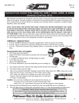
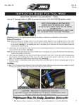
This tool is designed to function as a work bench tool and removes or installs Cruise Drive trap door bearings without using
an arbor press.
Other recommended JIMS tools for H-D Cruise Drive 6-speed:
No.
No.
No.
No.
No.
No.
No.
989 Mainshaft pulley locknut socket tool
900 Main drive gear and bearing remover / installer tool
985 Shift fork shaft remover tool
972 Main drive gear seal installer tool
992 Modular transmission stand, all Twin Cams
34902-84 Mainshaft race remover
786 Main Seal Installer Tool
No. 984
Trap door remover tool
1
Read complete instructions thoroughly before disassembling or
2
assembling. Refer to figure No.'s, part, list and reference photos.
3
NOTE: IF YOU DO NOT KNOW WHAT YOU’RE DOING , DO NOT
DO IT! ALWAYS WEAR SAFETY GLASSES OR OTHER FACE
AND EYE PROTECTION SUCH AS A FULL FACE SHIELD. FIG 1
JIMS IS NOT RESPONSIBLE FOR DAMAGE, INJURY, YOUR
WORK, OR THE QUALITY AND SAFETY OF YOUR WORK.
5
2 - 3/4'' Socket or box end wrench
1 - 3/16" Allen wrench or Allen socket
1- Safety glasses
1 - 3/8" Ratchet wrench
1- Quality retaining ring pliers
1 - H-D Service Manual
7
6
PARTS AVAILABLE SEPARATELY
No.
OTHER TOOLS RECOMMENDED FOR USE WITH THIS TOOL
4
1
2
3
4
5
6
7
Qty.
1
1
1
1
3
1
1
Description
Part No.
Lower plate
Upper plate
Installer pilot
Screw
Allen screw 1/4-20 x 2"
Nut 5/8-18
Washer 5/8 SAE
911-1
911-2
1077-2
1024
1203
1065
1064
Removing The Old Trap Door Bearing
1. Refer to H-D Service Manual for tear down of the transmission assembly to the point of removing the trap door from
the case using JIMS® tool No 984. Also you will need to remove mainshaft and countershaft gear assemblies from door
bearings per service manual.
2. Remove retaining rings that sit against the two door bearings on trap door.
Always wear safety glasses while performing this service.
3. We will instruct you on removing the front door bearing. Notice the two
dowel pins on the outer side of trap door. See Fig 2. Set tool lower plate
No. 911-1 on trap door and locate on dowel pin. You should have the
plate lasered letter "B" facing upward toward you. See Fig 2.
Dowel
Pin
4. Next place the upper tool plate No. 911-2 on top of lower plate No. 9111. The upper plate should have laser marked side with the letter "B" facing
you. Now install lightly lubed three 1/4" Allen screws No.1203. into the
three 1/4" holes on top of the upper plate thus attaching tool to trap door.
Torque 3 allen screws to 100 inch pounds. See Fig 3.
Dowel
Pin
FIG 2
555 Dawson Drive, Camarillo, CA 93012 Phone 805-482-6913 • Fax 805-482-9224
1
No.911-IS
Rev B
7-13
A Division of Thiessen Products, Inc.
Instruction Sheet For Tool #911
5. Next lube threads on tool screw No.1024. and install into No. 911-2 upper plate.
Lasered
“B”
Thread screw into bearing I.D. until screw is about a 1/2" past bearing. Then place
washer No.1064 and nut No.1065 onto end of No.1024 screw. Nut should
should be installed far enough to have full thread engagement. See Fig 4.
6. Next secure trap door to bench or soft jaw vice. Then turn tool screw No.1024
counter-clock wise with a 3/4" box end wrench, or socket and ratchet, until bearing comes free from door. See Fig 5.
Installing new trap door bearing
1. Inspect and clean trap door bearing surface and retaining ring groove. Clean as
needed. After cleaning secure trap door to bench or vice with soft jaws.
2. We will instruct you on installing the front door bearing. Lube O.D. surface of new
FIG 3
door bearing. Position lubed door bearing square over bore. Next Insert tool
No.1077-2 installer pilot into I. D. of bearing. See Fig 6.
3. Notice the two dowel pins on the outer side of trap door. See Fig 7. Set tool
lower plate No. 911-1 on trap door and locate on dowel pin. You should have the
lasered letter "B" plate facing upward toward you.
See Fig 7.
4. Next place the upper tool plate No. 911- 2 on top of lower plate No. 911-1. The
upper plate should have laser marked side with the letter "B" facing you. Now
install lightly lubed three 1/4" Allen screws No.1203. into the three 1/4" holes on
top of the upper plate thus attaching tool to trap door. Torque 3 allen screws to
100 inch pounds. See Fig 8.
5. Next lube threads on tool screw No.1024. and install into No. 911-2 upper. Turn
screw No.1024 clockwise into installer pilot
No.1077-2 using a 3/4" boxed end wrench
FIG 4
or socket and ratchet. Turn screw until bearing seats in bearing bore.
6. Install new door bearing retainer ring into
trap door.
7. When installing the rear trap door bearings
attach the upper & lower plates to door
with the engraved letter "A" facing you
when using this tool and follow the same
instructions. See Fig 9.
FIG 8
Engraved
“A”
FIG 5
FIG 9
FIG 7
Dowel
Pin
FIG 6
555 Dawson Drive, Camarillo, CA 93012 Phone 805-482-6913 • Fax 805-482-9224
2