1
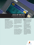
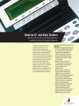
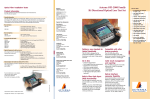
PCM-40 PCM Channel Analyzer PCS-40 PCM Channel Selector ACO . Ideal for installation, line-up, commissioning, fault localization and repairs . Handy, modern concept for field applications based on a lightweight analyzer module and IBM-compatible PC or notebook . Menu operation with color (or monochrome) VGA display . Graphical presentation of all results with flexible zooming and scaling . User definable: ± variable test parameters ± automatic test sequences ± graphical tolerance masks . Large memory for instrument settings and test results on PC hard disk . Numerical and graphical result printout on PC printers with selectable conditions . Complete digital and analog tests to ITU-T Recs. G.712 and O.133/O.162 . Complex impedances . PCM30 and PCM31 frame structures including CRC error detection code . Comprehensive codec, frame and CAS measurement capabilities incl. G.821 BERT . High accuracy and reproducibility of test results . Selective measurement capability with 30 Hz filter . Monitoring of signalling status for all 30 VF channels (CAS) For codec and line card tests on PCM multiplexers and digital exchanges Determining long-term stability (aging) Communications systems and network elements are subjected to a wide variety of environmental influences which adversely affect component performance to a greater or lesser degree. If the effect of such influences on, say, system gain are to be recorded, the PCM-40 provides support for this application. During system line-up, the results and instrument configuration are stored so that they can easily be recalled. In the subsequent measurement, these results are displayed within the tolerance mask and the new result trace is superimposed. The instrument then determines the difference between the two measurements so that the deviation can be seen directly. . Loop, MUX/DEMUX, and Drop & Insert modes for analog and 64 kbit/s interface Status of connected test signal The PCM-40 continuously monitors the connected test signal during the measurement and displays the result on the front panel and in detail on the screen. This keeps you informed of the status and prevents incorrect interpretation of the measurement results. Storage of measurement configurations The test equipment settings required for routine or specialized manually-performed measurements, along with explanatory comments, can simply be stored by the PCM-40. The number of setups which can be stored is limited only by the system resources of the computer you are using. . Optional 64 kbit/s interface with co- and contradirectional clock to ITU-T Rec. G.703 for D&I and BERT modes . Control of PCS-40 Channel Selector Quality monitoring in an idle channel Facilities for monitoring the quality of PCM systems which do not use CRC frames are limited to monitoring the frame alignment signals. The PCM-40 can, however, perform a loop-back or end-to-end measurement to ITU-T G.821 in an idle channel. The instrument transmits a test pattern which it then evaluates. The results can be shown as a table or as an error histogram. The fall-off in gain can be clearly seen. The blue trace was recorded on commissioning the system, the red trace at a later date. The ``DIFF RESLTº function determines the difference between the two traces. The zoom function and cursors allow every detail to be examined. A test configuration (setup) includes all test and interface parameters required to perform a measurement. The setup name is used to relate the setup to a particular device under test Automatic test sequences You can produce automatic test sequences by combining several test configurations together from the range of setups which you have stored. All of the measurement functions included in the PCM-40, along with any variations in test variables, parameters and tolerance limits, can be used for this in any order required. The sequence can be programmed to stop if an incorrect result is obtained or before each different measurement task. Monitoring digital paths in through mode or via high-impedance taps For long-term monitoring of 2 Mbit/s paths, the circuit can be looped-through the PCM-40 transparently or tapped via a high impedance monitor point. If the power supply fails during loop-through measurements, the signal path is not interrupted. The following measurements can be performed: ± Frame monitoring with FAS errors recorded as histograms ± Level, frequency and coder level monitoring including audio monitoring in a selected channel ± Recording of byte changes in the selected frame or data channel ± Signaling status display for individual channels Errors in the idle channel shown with their times of occurrence. Sporadic faults can thus be easily seen and matched in time to possible sources of interference. PCM-40 as an automated measuring system When testing PCM multiplexers, the PCS-40 Channel Selector connects up to 30 analog TX and RX channels sequentially to the PCM-40 analog test ports. The PCS-40 Channel Selector allows return loss and longitudinal conversion loss measurements on individual VF channels using the built-in bridges. Also test needing D.C. loop holding circuit or feeding bridge are possible. The result is a flexible and powerful test system well suited to production, installation and maintenance of 2 Mbit/s multiplexers. Ch x Tx PCM-40 Rx Ch x PCS-40 Channel Selector Tx Ch 1 to 30 Rx Ch 1 to 30 PCM MUX Automatic sequential connection of up to 30 analog Tx and Rx ports of a PCM MUX equipment to the PCM-40 Channel Analyzer 30 channel automatic sequential weighted noise measurement Test modes and configurations Test modes Gain or loss Test configuration Variable parameters A-A 6 A-D 6 D-A 6 D-D 6 Frequency Tone, MTTS/ Level/Tone, Nopise/Time . . . . Frequency & Channel Level & Channel 6 6 6 6 Channel T-D D-T T-T . 1) Transhybrid loss Frequency Level Channel 6 6 6 6 Frequency, Time . . . . 6 . Received level Channel Level Peak code Channel Level 6 . Coder offset Channel Level 6 . Total distortion Channel Level & Channel 6 6 6 6 Level/Tone, Noise . . . . Weighted noise Channel Time 6 . 6 . 6 . Far end crosstalk Channel Level 6 . 6 . 6 . Near end crosstalk Channel Level 6 . Group delay/Distortion Frequency/MTTS . . . . Dual tone intermodulation Channel Level 6 . 6 . 6 . 6 . Return loss Channel Frequency Frequency & Channel 6 Longitudinal balance Channel Frequency Frequency & Channel 6 Frame Monitor/O.162,G.821 Time (FAS, Channel) . Word test Time . . . . Event counter Time . . . . BERT/G.821 Time . . . . Channel associated signaling status Time . . . 6 . . Signaling distortion Drop & Insert A = 600, 900 O or complex, 4-wire or 2-wire analog interface D = 2048 kbit/s digital interface to ITU-T Recs. G.703, G.704 T = 64 kbit/s digital interface to ITU-T Rec. G.703 (optional) . . indicates available test configurations 6 available only with PCS-40 . 1) with external 2-wire termination Specifications PCM 40 PCM Channel Analyzer Analog signal generator Sinewave signal Frequency range . . . . . . . . . . . . . . . . . . . . . . . . . . . . . 200 to 3600 Hz Resolution . . . . . . . . . . . . . . . . . . . . . . . . . . . . . . . . . . . . . . . . . . . 4 Hz Frequency accuracy . . . . . . . . . . . . . . . . . . . . . . . . . . . . . . +50610 ± 6 Harmonic distortion . . . . . . . . . . . . . . . . . . . . . . . 456 dB at 0 dBm0 Level range . . . . . . . . . . . . . . . . . . . . . . . . . . . . . . . . ± 60 to +5 dBm0 Level increments . . . . . . . . . . . . . . . . . . . . . . . . . . . . . . . . . . . . 0.1 dB Dual-tone signal Frequency range . . . . . . . . . . . . . . . . . . . . . . . . . . . . . 200 to 3600 Hz Resolution . . . . . . . . . . . . . . . . . . . . . . . . . . . . . . . . . . . . . . . . . . . 4 Hz Level range . . . . . . . . . . . . . . . . . . . . . . . . . . . . . . . . . ± 60 to ±1 dBm0 Level . . . . . . . . . . . . . . . . . . . . . . . . . . . . . same for both spectral lines Pseudo-random noise signal to ITU-T Rec.O.131 Sequence repetition rate (period) . . . . . . . . . . . . . . . . . . . . . . 256 ms Bandwidth . . . . . . . . . . . . . . . . . . . . . . . . . . . . . . . . . . . 350 to 550 Hz Peak factor . . . . . . . . . . . . . . . . . . . . . . . . . . . . . . . . . . . . . . . . 10.5 dB Level range . . . . . . . . . . . . . . . . . . . . . . . . . . . . . . . . . . ± 60 to 0 dBm0 Level increments . . . . . . . . . . . . . . . . . . . . . . . . . . . . . . . . . . . . 0.1 dB MTTS (Multi Tone Test Signal) Frequency range . . . . . . . . . . . . . . . . . . . . . . . . . . . . . . 200 to 3860 Hz Level range . . . . . . . . . . . . . . . . . . . . . . . . . . . . . . . . ± 30 to +0 dBm0 Levels . . . . . . . . . . . . . . . . . . . . . . . . . . . same for all 37 spectral lines Output Impedance . . . . . . . . . . . . . . . . . . . . . . 600 O, 900 O, and complex 1) Return loss . . . . . . . . . . . . . . . . . . . . . . . . . 436 dB (200 to 4000 Hz) Balance . . . . . . . . . . . . . . . . . . . . . . . . . . . 450 dB (200 to 3600 Hz) Relative level/increments . . . . . . . . . . . . . . . . ±15 to +5 dBr/0.1 dB Max. d.c. voltage . . . . . . . . . . . . . . . 60 V (between a/b and ground) Connector . . . . . . . . . . . . . . . . . . . . . . . . . . . . . . . balanced, 3pole CF Auxiliary signal generator Sinewave signal Frequency range . . . . . . . . . . . . . . . . . . . . . . . . . . . . . . 200 to 3600 Hz Resolution . . . . . . . . . . . . . . . . . . . . . . . . . . . . . . . . . . . . . . . . . . . 4 Hz Level range/increments . . . . . . . . . . . . . . . ± 60 to ± 30 dBm0/0.1 dB Impedance . . . . . . . . . . . . . . . . . . . . . . . . . . . . . . . . . . . . . . . . . . 600 O Connector. . . . . . . . . . . . . . . . . . . . . . . . . . . . . . . . balanced, 3pole CF Output Impedance . . . . . . . . . . . . . . . . . . . . . . . . . . . . . . . . . . . . . . . . . 600 *O Return loss . . . . . . . . . . . . . . . . . . . . . . . . . 436 dB (300 to 3600 Hz) Balance . . . . . . . . . . . . . . . . . . . . . . . . . . . . 446 dB (200 to 3600 Hz) Max. d.c. voltage . . . . . . . . . . . . . . . 60 V (between a/b and ground) Connector . . . . . . . . . . . . . . . . . . . . . . . . . . . . . . . balanced, 3pole CF Analog receiver Filters Flat filter . . . . . . . . . . . . . . . . . . . . . . . . . . . . . . . . . . . . 200 to 3600 Hz Psophometric filter . . . . . . . . . . . . . . . . . . . . . . . .to ITU-T Rec. O.41 Selective filter . . . . . . . . . . . . . . . . . . . . . . . between 200 and 3600 Hz, center frequency settable in 4 Hz increments, bandwidth 30 Hz Filter for distortion measurement . . . . . . . . . . . . . . . . 850 to 3250 Hz or 1380 to 3240 Hz Notch filter . . . . . . . . . . . . at aux. signal frequency, bandwidth 30 Hz Level measuring range (minimum) Signal level . . . . . . . . . . . . . . . . . . . . . . . . . . . . . . . . . ± 60 to +8 dBm0 Resolution . . . . . . . . . . . . . . . . . . . . . . . . . . . . . . . . . . . . . . . . 0.01 dB Noise, crosstalk . . . . . . . . . . . . . . . . . . . . . . . . . . . . . . . . . ± 80 to 0 dBm0 Resolution . . . . . . . . . . . . . . . . . . . . . . . . . . . . . . . . . . . . . . . . 0.01 dB Relative level range/increments . . . . . . . . . . . . ±15 to +5 dBr/0.1 dB Group delay distortion. . . . . . . . . . . . . . . . . . . . . . . . . . . . . . . 0 to 10 ms Resolution . . . . . . . . . . . . . . . . . . . . . . . . . . . . . . . . . . . . . . . . . 0.1 ms Input Impedance . . . . . . . . . . . . . . . 600 O, 900 O, 430 kO and complex 1) Return loss . . . . . . . . . . . . . . . . . . . . . . . . . 436 dB (200 to 4000 Hz) Balance . . . . . . . . . . . . . . . . . . . . . . . . . . . 450 dB (200 to 4000 Hz) Max. d.c. voltage . . . . . . . . . . . . . . . . 60 V (between a/b and ground) Connector. . . . . . . . . . . . . . . . . . . . . . . . . . . . . . . . balanced, 3pole CF Digital signal generator PCM frame structure . . . . . . . . . . . . . . . . . . . . . . . to ITU-T Rec. G.704 32 channel PCM frame containing 30 telephone channels, or 31 telephone channels . . . . . . . . . . . . . . . . . . . . . . . time slots 1 to 31 Encoding law . . . . . . . . . . . . . . . . . . . . . . ITU-T Rec. G.711, A or m law Sinewave signal Frequency range . . . . . . . . . . . . . . . . . . . . . . . . . . . . . . 200 to 3600 Hz Resolution . . . . . . . . . . . . . . . . . . . . . . . . . . . . . . . . . . . . . . . . . . . 4 Hz Frequency accuracy . . . . . . . . . . . . . . . . . . . . . . . . . . . . . . +50610 ± 6 Harmonic distortion . . . . . . . . . . . . . . . . . . . . . . . . . as per A or m law Level range/increments . . . . . . . . . . . . . . . ± 60 to +3.1 dBm0/0.1dB Dual-tone signal Frequency range . . . . . . . . . . . . . . . . . . . . . . . . . . . . . . 200 to 3600 Hz Resolution . . . . . . . . . . . . . . . . . . . . . . . . . . . . . . . . . . . . . . . . . . 4 Hz Level range . . . . . . . . . . . . . . . . . . . . . . . . . . . . . . . . ± 60 to ± 5 dBm0 Pseudo-random noise signal to ITU-T Rec. O.131 Sequence repetition rate (period) . . . . . . . . . . . . . . . . . . . . . . 256 ms Bandwidth . . . . . . . . . . . . . . . . . . . . . . . . . . . . . . . . . . . 350 to 550 Hz Peak factor . . . . . . . . . . . . . . . . . . . . . . . . . . . . . . . . . . . . . . . . 10.5 dB Level range . . . . . . . . . . . . . . . . . . . . . . . . . . . . ± 60 to 0 dBm0/0.1 dB MTTS (Multi-Tone Test Signal) Frequency range . . . . . . . . . . . . . . . . . . . . . . . . . . . . . . 200 to 3860 Hz Levels . . . . . . . . . . . . . . . . . . . . . . . . . . . same for all 37 spectral lines Level range/increments . . . . . . . . . . . . . . . . . . ± 30 to 0 dBm0/0.1 dB Group delay measuring signal . . . . . . . . . . . . . . . . . . . . . . . . . . . . MTTS Test patterns . . . . . . . . . . . . . . . . . . . . PRBS6, PRBS9, PRBS11, PRBS15 Insertion in . . . . . . . . . . . . . . . . . . . . . . . . . . . .voice channels 1 to 30 Freely selectable n68 bit word sequence . . . . . . . . . . . . . . . n = 1 to 60 Insertion in . . . . . . . . FAS, FAW, MFW, channel, signalling channel Repetitions . . . . . . . . . . . . . . . . . . . . . . . . . . . . . 1 to 9999 or continuous Freely selectable FAS sequence . . . . . . . . . . . . . . . n67 bits, n = 1 to 60 Freely selectable MFAS sequence . . . . . . . . . . . . . . n64 bits, n = 1 to 60 Error insertion . . . . . . . . . . . . . . . . . . . . . . . FAS, MFAS, MFW, channel, signalling channel Error ratio . . . . . . . . . . . . . . . . . . . . . . . . . . . . . . 5610 ± 3 to 5610-7 Digital milliwatt signal . . . . . . . . . . . . . . . . . . . . . . to ITU-T rec. G.711 Output Bit rate . . . . . . . . . . . . . . . . . . . . . . . . . . . . . . . . . . . . . . . . 2048 kbit/s Interface parameters . . . . . . . . . . . . . . . . . . . . . . to ITU-T rec. G.703 Line code . . . . . . . . . . . . . . . . . . . . . . . . . . . . . . . . . . . HDB3 or AMI Unbalanced impedance . . . . . . . . . . . . . . . . . . . . . . . . . . . . . . . . 75 O Connector . . . . . . . . . . . . . . . . . . . . . . . . . . . . . . . . . coaxial, BNC Balanced impedance . . . . . . . . . . . . . . . . . . . . . . . . . . . . . . . . . 120 O Connector . . . . . . . . . . . . . . . . . . . . . . . . . . . . . balanced, 3pole CF Operating mode Loop-through (2 Mbit/s) Test pattern insertion into one time slot Analysis of one time slot Generator operation from internal clock. . . . . . . . . . . . . . . . . . . . . . 2048 kHz +50610 ± 6 or external clock. . . . . . . . . . . . . . . . . . . . . . . 2048 kHz +100610 ± 6 or clock derived from received signal Digital loops 2 Mbit/s loop . . . . . . . . . . . . . . . . . . . all time slots switched through 2 Mbit/s loop . . . . . . . . . . one selected time slot generated internally, remainder switched through 2 Mbit/s loop . . . . . . . . . . . . . . . . . . . all time slots switched through but channels shifted by 15 1) Complex impedance: 220 O in series with 820 O in parallel with 115 nF; other values on request Digital receiver PCM frame structure . . . . . . . . . . . . . . . . . . . . . . . to ITU-T Rec. G.704 (see digital signal generator) Encoding law . . . . . . . . . . . . . . . . . . . . to ITU-T Rec. G.711, A or m law Filters Flat filter . . . . . . . . . . . . . . . . . . . . . . . . . . . . . . . . . . . . 200 to 3600 Hz Psophometric filter . . . . . . . . . . . . . . . . . . . . . . . .to ITU-T Rec. O.41 up to 3960 Hz Selective filter . . . . . . . . . . . . . . . . . . . . . . . between 200 and 3600 Hz, center frequency can be set with 4 Hz increments, bandwidth 30 Hz Filter for distortion measurement . . . . . . . . . . . . . . . . 850 to 3250 Hz or 1380 to 3240 Hz Notch filter . . . . . . . . . . . . at aux. signal frequency, bandwidth 30 Hz Alarm detection . . . . . . . . . . . . . .no signal, frame loss, multiframe loss, AIS, multiframe AIS, remote alarm, remote multiframe alarm Evaluation Bit error count, event count, recording of transients in digital words . . . . . . . . . . . . . . . . . . FAS, FAW, MFW, signalling channel, telephone channel Telephone channel r.m.s value measurement . . . . . . . . . . . . . . . . . . . . . . . . . . . . . . . ± 80 to +6 dBm0 ITU-T G.821 evaluation. . . . . . . . . . . . . . . . . . . bit errors, FAS errors Error results displayed as histograms Input Bit rate . . . . . . . . . . . . . . . . . . . . . . . . . . . . . . . . . . . . . . . . .2048 kbit/s Interface parameters . . . . . . . . . . . . . . . . . . . . . . to ITU-T Rec. G.703 Line code . . . . . . . . . . . . . . . . . . . . . . . . . . . . . . . . . . . . HDB3 or AMI Unbalanced input impedance . . . . . . . . . . . . . . . . . . 75 O or 42 kO Connector . . . . . . . . . . . . . . . . . . . . . . . . . . . . . . . . . . coaxial, BNC Balanced input impedance . . . . . . . . . . . . . . . . . . . . 120 O or 42 kO Connector . . . . . . . . . . . . . . . . . . . . . . . . . . . . . balanced, 3pole CF Clock. . . . . . . . . . . . . . . . . . . . . . . . . . . . . . . . . . . from received signal Pulling range . . . . . . . . . . . . . . . . . . . . . . . . . . . . . . . . +100610 ± 6 Measurement interval . . . . . . . . . . . . . . . . . . . . . . . . . . 60 s to 72 h Instrument set-up memory . . . . . . . . . . depends on PC resources Automatic measurement sequences available Individual measurements linked to a sequence . . . . . . . . . . . . . . . . . . . . . . . . . . max. number depends on PC resources available Result documentation Result output to external printer Output in table or graph formats Result output as ASCII file to disk Result in table format can be saved to disk with printout using DOS ªPRINTº command. Result storage and test configuration storage Depends on PC resources available Self-test and level calibration Triggered automatically by opening the measurement menu Codec interface/Handset interface Input/output impedance . . . . . . . . . . . . . . . . . . . . . . . . . . . . . . . . 600 O Connector . . . . . . . . . . . . . . . . . . . . . . . . . . . . . . . . . . . . . . . . . . RJ11 64 kbit/s interface (optional) Output/input . . . . . . . . . . . . . . . . . . . . . . . . . . . . . to ITU-T Rec. G.703 Modes . . . . . . . . . . . . . . . . . . . . . . . . codirectional, contradirectional Balanced output . . . . . . . . . . . . . . . . . . . . . . . . . . . . . . . . . . . . . . . . 120 O Connector. . . . . . . . . . . . . . . . . . . . . . . . . . . . . . . . balanced, 3pole CF Clock output. . . . . . . . . . . . . . . . . . . . . . . . . . . . . . . . . . . . . . . . . . . 120 O Connector. . . . . . . . . . . . . . . . . . . . . . . . . . . . . . . . balanced, 3pole CF General specifications Control computer for PCM-40 PC AT 486 WIN 3.1, WIN 95, 98, NT min. 600 kB free conventional memory min. 256 kB free EMS memory min. 40 MB free HD space VGA monitor (color or monochrome) serial or GPIB (National Instr.) interface Communication interfaces for PCM-40 Serial I (for computer control) . . . . . . . . . . . . . . . . . . . RS232C/V.24 Serial II (for modem connection) . . . . . . . . . . . . . . . . . RS232C/V.24 GPIB/ 5IEC 6254 8.5 /IEEE-488.1-1978 (for computer control) Power supply External adapter with a.c. line cord AC supply . . . . . . . . . . . . . . . . . . . . . . . . . . 100 to 240 V, 50 to 60 Hz Power consumption . . . . . . . . . . . . . . . . . . . . . . . . . . . . . . . . . 25 VA Ambient temperature Nominal range of use. . . . . . . . . . . . . . . . . . . . . . . . . . . +5 to +45 C Limits range of use (for 2 hours) . . . . . . . . . . . . . . . . . . . 0 to +55 C Storage and transport range . . . . . . . . . . . . . . . . . . . . ± 40 to +70 C Air humidity Nominal range of use . . . . . . . . 20 to 80% r.h. (520 g/m3 absolute) Dimensions (l6w6h) . . . . . . . . . . . . . . . . . . . . . . 2906230670 mm Weight . . . . . . . . . . . . . . . . . . . . . . . . . . . . . . . . . . . . . . . . approx. 3.5 kg Test ports (Ch x) Maximum level . . . . . . . . . . . . . . . . . . . +20 dBm Max. d.c. voltage 60 V (between a/b and ground) Max d.c. current. . . . . . . . . . . . . . . . . . . . 100 mA Impedance . . . . . . . . . . . . . . . . . . . . . . . . . . 600 O Insertion loss between test port and selected Tx/Rx port (200 Hz to 4 kHz). . . . . . . .50.02 dB Connector. . . . . . . . . . . . . . . balanced, 3-pole CF Access ports (Ch 1 to Ch 30) Balanced through-switching of up to 30 VF channels in Tx and Rx directions Connector DIN 41612 type socket, 64 way, female Switching time . . . . . . . . . . . . . . . . . . . . . 510 ms Return loss measurement Built-in bridge for return loss measurements on a selectable VF channel Measurement range . . . . . . . . . . . . . . . 0 to 45 dB Frequency range . . . . . . . . . . . . . 200 Hz to 4 kHz Accuracy 0 to 30 dB . . . . . . . . . . . . . . . . . . . . . . . . . . 1 dB 30 to 45 dB . . . . . . . . . . . . . . . . . . . . . . . . . 2 dB Reference impedance internal . . . . . . . . . . . . . . . . . . . . . . . . . . . 600 O external (connected to auxiliary input) . . . . . . . . . . . . . . . . . . . . . . 600 to 900 O Max. input level 200 Hz to 300 Hz . . . . . . . . . . . . . . . . . ± 6 dBm 300 Hz to 4 kHz . . . . . . . . . . . . . . . . . . . 0 dBm Longitudinal conversion loss (LCL) measurement Built-in bridge for LCL measurements according to ITU-T Rec. O.9 on a selectable VF channel Measurement range . . . . . . . . . . . . . . . 5 to 56 dB Frequency range . . . . . . . . . . . . . 200 Hz to 4 kHz Accuracy 5 to 46 dB . . . . . . . . . . . . . . . . . . . . . . . . . . 1 dB 46 to 56 dB . . . . . . . . . . . . . . . . . . . . . . . . . 2 dB Terminating impedance . . . . . . . . . . . . . . . 600 O Max. input level . . . . . . . . . . . . . . . . . . . . ± 6 dBm DC current loop Two built-in current loops connected to each test port DC current . . . . . . . . . . . . . . . . . . . . . . 5150 mA Voltage drop at 20 mA (100 mA) . . . . . . . . . . . . . . . . . .55.5 V (512 V) Output impedance (200 Hz to 4 kHz) . . . . . . . . . . . . . approx. 30 kO DC feeding bridge Two built-in current loops connected to each test port Supply voltage (It = 0) . . . . . . . . . . . approx. 30 V Supply current (Rt = 400 O) . . . . . . . . . 420 mA Supply current (Rt = 0 O) . . . . . . approx. 38 mA Output impedance (200 Hz to 4 kHz) . . . . . . . . . . . . . approx. 50 kO LCL (200 Hz to 4 kHz) . . . . . . . . . . . . . . 445 dB Line status indication (TX and RX) Line feeding voltage on Line looped Remote control Control of all functions from PCM-40 Channel Analyzer or personal computer via GPIB/IEC625/ IEEE488 interface Interface . . . . . . . . . . . . . . . . IEEE 488 connector General specifications Power supply External adapter with a.c. line cord AC supply . . . . . . . . . . . 100 to 240 V, 50 to 60 Hz Power consumption . . . . . . . . . . . . . . . . . . . 10 VA (One adapter can supply both the PCM-40 and PCS-40) Ambient temperature Nominal range of use. . . . . . . . . . . . +5 to +45 C Limits range of use (for 2 hours) . . . 0 to +55 C Storage and transport range . . . . . ± 40 to +70 C Air humidity Nominal range of use. . . . . . . . . . . 20 to 80% r.h. (520 g/m3 absolute) Dimensions (l6w6h) . . . . . . . 2906230670 mm Weight . . . . . . . . . . . . . . . . . . . . . . . . . approx. 2 kg Ordering information PCM-40 Channel Analyzer EL 3039/01 Including AC adapter, RS232C/V.24 cable and operation manual (in English) A separate PC is required for operation Calibration report for PCM-40 EL 3039/60 PCS-40 Channel Selector EL 3039/20 Including return loss and longitudinal conversion loss (LCL) measuring bridge, DC current loop and DC feeding bridge, cables for interconnection of PCM-40 and PCS-40, 64 way female connector set for accessing PCM MUX and operation manual (in English) REG.NO 572 - 02 Global Headquarters 20400 Observation Drive Germantown, Maryland 20876-4023 USA Toll Free 1-800-638-2049 Tel. +1-301-353-1550 Fax +1-301-444-8468 www.acterna.com Regional Sales Headquarters North America 20400 Observation Drive Germantown, Maryland 20876-4023 USA Toll Free 1-800-638-2049 Tel. +1-301-353-1550 Fax +1-301-444-8468 Latin America Av. Eng. Luis Carlos Berrini, 936-8/9. Andar 04571-000 So Paulo, SP Brazil Tel. +55 11 5503 3800 Fax +55 11 5505 1598 Asia-Pacific 42 Clarendon Street PO Box 141 South Melbourne, Victoria 3205 Australia Tel. +61 3 9690 6700 Fax +61 3 9690 6750 Western Europe Arbachtalstrasse 6 72800 Eningen u.A. Germany Tel. +49 7121 86 2222 Fax +49 7121 86 1222 East Europe, Middle East & Africa Elisabethstrasse 36 PO Box 13 2500 Baden Austria Tel. +43 2252 85521 0 Fax +43 2252 80727 CIS Countries 1st Neopalimovskiy Per. 15/7 (4th floor) 119121 Moscow Russia Tel. +7 095 248 2508 Fax +7 095 248 4189 ã Copyright 2001 Acterna, LLC. All rights reserved. Subject to change without notice ± CO/EN/D146/0401/AE repl D044 ± Printed in Germany Specifications PCS 40 PCM Channel Selector Acterna is present in more than 80 countries. To find your local sales office, go to www.acterna.com Options 64 kbit/s Interface (for codirectional/contradirectional clock) for BERT and D&I Impedance modification (replaces complex impedance) Accessories GH-1 DC Loop Holding/ Line Feeding Nylon Carrying Case EL 3039/01 EL 3039/02 BN 0984/00.12 EL 2237/01 (for PCM-40, Notebook PC and accessories) TPK-960/33 Transport Container BN 960/00.09 (for PCM-40, PCS-40, Notebook PC and accessories) 64-way female connector set for PCS-40 IEEE Interface cable for PCS-40 AC Adapter for PCS-40 EL 3039/203 EL 3039/201 EL 3039/202 Documentation Service manual for PCM/PCS-40 (in English) EL 3039/83 ACO ACTERNA Complementary Operations Arbachtalstrasse 6 Germany Tel. +49 7121 86 1364 Fax +49 7121 86 1103 e-mail: [email protected]