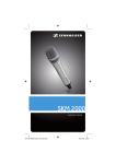
1
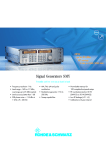
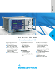
ValueTronics International Inc. - www.valuetronics.com - Toll Free: 1.800.552.8258 or 1.847.468.8258
Spectrum and Network Analysis
Contents Overview
Chapter Overview
152
Type Index
R&S Addresses
Spectrum Analyzers FSEA, FSEB, FSEM, FSEK
20 Hz to 40 GHz
High-performance analyzers
for digital mobile radio and
universal applications
FSEK30 (photo 42756)
Brief description
An extremely wide intermodulationfree dynamic range of 110 dB (with
• 3rd-order intercept point >+15 dBm
• 1 dB compression point of RF input
FSEA, FSEB, FSEM and FSEK are
advanced, high-speed and high-per-
10 Hz resolution bandwidth) ensures
reliable measurements on highly lin-
>+10 dBm
• Phase noise at 20 kHz from carrier:
formance analyzers tailored to the
requirements of modern digital com-
ear amplifiers as well as correct analysis of broadband complex signals.
down to −123 dBc (FSEA)
• Intermodulation-free dynamic range
munication systems. They can also be
used as general-purpose analyzers for
From the available frequency ranges,
110 dB
• Measurement uncertainty up to
many applications. High measurement speed, modular design and
the basic models 20 and the high-performance models 30 the right instru-
1 GHz: 1 dB
• Headphones connector and built-in
excellent technical features make for
an excellent price/performance ratio.
ment can be chosen for every application. Models 20 can easily be
loudspeaker for AM/FM
• Internal RF trigger for GATED
In addition to measurement functions
upgraded to give the full range of functions of models 30.
SWEEP measurements
• Speed records:
for digital communication systems,
such as 2 µs sweep time in ZERO
To ensure correct measurement of time
SPAN mode, pretrigger and trigger
delay, gated sweep and adjacent-
variants or pulse-modulated signals,
the FSE features digital resolution fil-
with a fully synchronized sweep
– added speed is not at the
channel power measurement, these
spectrum analyzers feature a wide
ters (10 Hz to 1 kHz) with a response
corresponding to that of analog filters.
expense of frequency accuracy
but even enhances it
dynamic range, a very low measurement uncertainty of 1 dB and a low-
It additionally provides FFT bandwidths down to 1 Hz (models 30).
noise synthesizer.
– Shortest FULL SPAN sweep time
is 5 ms (for 3.5 and 7 GHz span)
– Shortest ZERO SPAN sweep time
is 1 µs (100 ns/div) – ideal for
high-resolution measurements on
pulse edges
Main features
FSE analyzers have low inherent noise
and a wide dynamic range, so that for
• Resolution bandwidths 1 Hz (up to
instance measurement of GSM power
ramps is no problem.
10 MHz), adjustable in steps of
1/2/3/5/10
– More than 20 sweeps/s – an
optimal prerequisite for fast
alignments or applications in production
• Displayed noise floor down to
−160 dBm (FSEA)
Contents Overview
Chapter Overview
Type Index
R&S Addresses
ValueTronics International Inc. - www.valuetronics.com - Toll Free: 1.800.552.8258 or 1.847.468.8258
Spectrum and Network Analysis
Contents Overview
Type Index
Chapter Overview
R&S Addresses
Spectrum Analyzers FSEA, FSEB, FSEM, FSEK
From AF to microwave
Measurement functions
• Limit lines
• User-configurable menu and key-
FSEM/K21/31 (corresponding to
FSEM/K20/30 with option FSE-B21)
• Up to 8 markers
• Marker functions for the direct
board macros
• Adjacent-channel power measure-
allow frequency range extension by
means of external mixers. Continuous
measurement of
– phase noise and
ment for up to 7 channels
• RMS detector
automatic signal identification, which
is used to suppress unwanted image
phase power density
– NEXT MIN/PEAK, NEXT MIN/
Operation
frequency bands and mixture products, ensures fast and easy measure-
PEAK RIGHT, NEXT MIN/PEAK
LEFT
ments. Due to the built-in diplexer,
three-port as well as two-port mixers
• Frequency counter with selectable
resolution
softkeys makes for extremely fast and
easy operation. The operating conven-
can be used.
• LOW NOISE, NORMAL and LOW
DISTORTION modes to cater for
ience based on a wide variety of evaluation routines and marker functions
low-intermodulation and low-noise
operation
can be accessed via the menus. Complicated tree structures could be
• Plotting or printout in background
operation or file saving in standard
avoided by using menus of lateral
structure and fixed control keys. Com-
graphic format
• Simultaneous display of four traces
plete setups and traces, limit lines as
well as macros can be stored on the
• Definition of all important parameters for each waveguide band
• Selectable colour setup
• Numerous level and frequency lines
hard disk or on floppy disks.
separately
• Frequency-dependent consideration
• Split-screen display with independent windows
of mixer conversion loss
• Storage of parameters on hard disk
• Quasi-analog display
• Frequency zoom
The external mixer measurement function features great ease of operation:
• Definition of frequency range and
harmonics by selection of a
waveguide band
A combination of hardkeys and
Overview of configurations and options
The analyzers of the FSE family are of modular design throughout. In the table below the right solution tailored to the needs
of the various applications can be found. Except for the Colour Display FSE-B1 all options can easily be retrofitted (1) Cannot
be retrofitted, factory-fitted only).
FSE-B3
Contents Overview
Chapter Overview
1073.5244.02
Type Index
FSEK 31
TV Demodulator Frame frequency and line trigger, trigger
delay and gap sweep allow convenient selection and analysis
of individual lines
FSEK 30
1073.5040.02
1)
FSEK 21
FSE-B2
FSEK 20
7 GHz Frequency Extension
FSEM 31
1073.4990.02
FSEM 30
FSE-B11)
FSEM 21
Colour Display
FSEM 20
Order No.
FSEB 30
Type
FSEB 20
Designation, characteristics (hardware)
FSEA 30
Note: max. two of the options -B4, -B7 can be fitted in FSEM20
FSEA 20
12
153
m l m l m m l l m m l l
m m l l − − − − − − − −
m m m m m m m m m m m m
R&S Addresses
ValueTronics International Inc. - www.valuetronics.com - Toll Free: 1.800.552.8258 or 1.847.468.8258
Spectrum and Network Analysis
Contents Overview
154
Type Index
Chapter Overview
R&S Addresses
Vector Signal Analyzer Demodulation of digitally modulated
signals
FSE-B7
1066.4317.02
m l m l m m l l m m l l
m m m m m m m m m m m m
Tracking Generator (9 kHz to 3.5 GHz)
FSE-B8
1066.4469.02
Tracking Generator with I/Q Modulator (9 kHz to 3.5 GHz)
FSE-B9
1066.4617.02
Tracking Generator (9 kHz to 7 GHz)
FSE-B10
1066.4769.02
Tracking Generator with I/Q Modulator (9 kHz to 7 GHz)
FSE-B11
1066.4917.02
Switchable Attenuator for Tracking Generators FSE-B8/9/10/11
(0 to 70 dB)
FSE-B12
1066.5065.02
m m m − m m m − m m
− − m m m − m m m − m m
m m m m m m m m m m m m
Computer Function Additional use of 486 processor for DOS
or Windows applications
FSE-B15
1073.5696.02
m m m m m m m m m m m m
Ethernet Interface LAN integration for use in production
FSE-B16
1073.5973.02
2nd IEC/IEEE-Bus Interface
FSE-B17
1066.4017.02
External Mixer
FSE-B21
1084.7243.02
Increased Level Accuracy up to 2 GHz
FSE-B22
1073.5544.02
m m m m m
m m m m m
− − − − m
m m m m m
m
m
l
m
m
m
m
m
m
m
l
m
m
m
m
m
m
m
l
m
m
m
m
m
m
m
l
m
Designation, characteristics (software)
Type
Order No.
FSEM 31
FSEK 20
FSEK 21
FSEK 30
FSEK 31
Application Firmware for mobile radio transmitter measurements to GSM900 specs 11.20 (mobiles), GSM 1800 and
GSM1900
FSE-K10
1057.3092.02
m m m m m m m m m m m m
Application firmware for mobile radio transmitter measurements to GSM900 specs 11.20 (BTS), GSM1800 and
GSM1900
FSE-K11
1057.3392.02
m m m m m m m m m m m m
Noise Measurement Software Noise figure or noise temperature
measurement (Y-factor method) from 100 kHz, 2nd-stage correction, measurements on frequency converters, editor for ENR
tables, consideration of isolator/cable attenuation
FSE-K3
1057.2996.02
m m m m m m m m m m m m
m m
m m
−
FSEK 31
1073.5544.02
FSEK 30
FSE-B5
FSEK 21
FFT Filter (1 Hz to 1 kHz)
FSEK 20
m l m l m m l l m m l l
FSEM 30
FSEM 31
1073.5396.02
FSEM 21
FSEM 30
FSE-B4
FSEM 20
FSEM 21
FSEA 20
Low Phase Noise and OCXO Typ. phase noise only −125 dBc
(BW = 1 Hz, at 10 kHz from carrier), ideal for measuring
phase noise of oscillators or adjacent-channel power of radio
equipment
FSEA 20
FSEM 20
Order No.
FSEB 30
Type
FSEB 20
Designation, characteristics (hardware)
1)
FSEA 30
Spectrum Analyzers FSEA, FSEB, FSEM, FSEK
−
−
−
−
−
−
−
−
−
−
−
−
−
−
−
−
−
−
−
−
−
l Fitted in basic model
FSEB 30
FSEB 20
FSEA 30
1) Factory-fitted only
m Option
Contents Overview
Chapter Overview
Type Index
R&S Addresses
ValueTronics International Inc. - www.valuetronics.com - Toll Free: 1.800.552.8258 or 1.847.468.8258
Spectrum and Network Analysis
12
Type Index
Chapter Overview
Contents Overview
155
R&S Addresses
Spectrum Analyzers FSEA, FSEB, FSEM, FSEK
Model-dependent specifications in brief
Frequency
FSEA20
FSEA30
FSEB20
FSEB30
FSEM20/21
FSEM30/31
FSEK20/21
FSEK30/31
Frequency range
9 kHz to
3.5 GHz
20 Hz to
3.5 GHz
9 kHz to
7 GHz
20 Hz to
7 GHz
9 kHz to
26.5 GHz
20 Hz to
26.5 GHz
9 kHz to
40 GHz
20 Hz to
40 GHz
Refer. frequency (aging) 1 x 10⁻⁶/year 2 x 10⁻⁷/year 1 x 10⁻⁶/year 2 x 10⁻⁷/year 1 x 10⁻⁶/year 2 x10⁻⁷/year
2 x 10⁻⁷/year —
2 x 10⁻⁷/year —
With option FSE-B4
2 x 10⁻⁷/year —
1 x 10⁻⁶/year 2 x10⁻⁷/year
2 x 10⁻⁷/year —
Spectral purity
SSB phase noise, referred to 1 Hz bandwidth, f ≤500 MHz
—
<−87 dBc
—
100 Hz1)
1 kHz1)
<−85 dBc
<−107 dBc
<−79 dBc
10 kHz1)
<−96 dBc
<−120 dBc
<−90 dBc
100 kHz2)
<−119 dBc
<−117 dBc
<−113 dBc
1 MHz1)
<−135 dBc
<−135 dBc
<−129 dBc
Resolution bandwidths
3 dB bandwidths
Steps
Shape factor 60 : 3 dB
(1 kHz to 2 MHz)
Video bandwidths
Steps
<−81 dBc
<−100 dBc
<−114 dBc
<−111 dBc
<−129 dBc
—
<−79 dBc
<−90 dBc
<−113 dBc
<−129 dBc
<−81 dBc
<−100 dBc
<−114 dBc
<−111 dBc
<−129 dBc
—
<−79 dBc
<−90 dBc
<−113 dBc
<−129 dBc
<−81 dBc
<−100 dBc
<−114 dBc
<−111 dBc
<−129 dBc
10 Hz to
10 MHz
1/2/3/5
<15
1 Hz to
10 MHz
1/2/3/5/10
<12
10 Hz to
10 MHz
1/2/3/5
<15
1 Hz to
10 MHz
1/2/3/5/10
<12
10 Hz to
10 MHz
1/2/3/5
<15
1 Hz to
10 MHz
1/2/3/5
<12
10 Hz to
10 MHz
1/2/3/5
<15
1 Hz to
10 MHz
1/2/3/5
<12
1 Hz to
10 MHz
1/2/3/5
1 Hz to
10 MHz
1/2/3/5
1 Hz to
10 MHz
1/2/3/5
1 Hz to
10 MHz
1/2/3/5
1 Hz to
10 MHz
1/2/3/5
1 Hz to
10 MHz
1/2/3/5
1 Hz to
10 MHz
1/2/3/5
1 Hz to
10 MHz
1/2/3/5
—
—
<−84
<−104
<−124,
typ. −129
<−138,
typ. −140
<−135,
typ. −138
<−138,
typ. −140
<−135,
typ. −138
<−120,
typ. −125
<−116,
typ. −122
<−74
<−104
<−119
<−129
<−142,
typ. −145
<−138,
typ. −140
<−135,
typ. −138
<−138,
typ. −140
<−135,
typ. −138
<−120,
typ. −125
<−116,
typ. −122
Level
Displayed noise floor, average level in dBm (10 Hz bandwidth, 0 dB RF attenuation,VBW
20 Hz
—
−80
—
−74
1 kHz
—
−110
—
−104
10 kHz
−90
−125
−84
−119
100 kHz
−110
−135
−104
−129
1 MHz
<−125,
<−145,
<−119,
<−142
typ.−130
typ. −150
typ. −124
10 MHz to 3.5/6 GHz <−140,
<−145,
<−142,
<−142,
typ. −145
typ. −150
typ. −147
typ. −147
6 GHz to 7 GHz
—
—
<−139
<−139
= 1 Hz, no signal at RF input)
—
<−74
—
<−104
<−84
<−119
<−104
<−129
<−124,
<−142,
typ. −129
typ. −145
<−138,
<−138,
typ. −140
typ. −140
<−135,
<−135,
typ. −138
typ. −138
<−138,
<−138,
typ. −140
typ. −140
<−135,
<−135,
typ. −138
typ. −138
—
—
7 GHzto 18 GHz
—
—
—
—
18 GHz to 26.5 GHz
—
—
—
—
26.5 GHz to 30 GHz
—
—
—
—
30 GHz to 40 GHz
—
—
—
—
Max. dynamic range
Displayed noise floor
at 1 dB compression
10 Hz bandwidth 1 Hz bandwidth 10 Hz bandwidth 1 Hz bandwidth 10 Hz bandwidth 1 Hz bandwidth 10 Hz bandwidth 1 Hz bandwidth
155 dB
165 dB
152 dB
162 dB
150 dB
160 dB
150 dB
160 dB
Max. intermodulation-free range
50 MHz to 3.5/7 GHz 105 dB
100 MHz to 26.5 GHz —
115 dB
—
—
105 dB
—
115 dB
—
—
103 dB
—
—
112 dB
—
103 dB
—
112 dB
1) Valid at ≤10 kHz for average control loop bandwidth; automatic setting of this bandwidth at span ≤50 kHz and resolution filter <1 kHz; other bandwidths
can be switched manually to "medium". Value at 10 kHz valid for span/sweep time <0.4 MHz/ms with FSEB/M/K20/21.
2) Valid for span >100 kHz.
Contents Overview
Chapter Overview
Type Index
R&S Addresses
ValueTronics International Inc. - www.valuetronics.com - Toll Free: 1.800.552.8258 or 1.847.468.8258
Spectrum and Network Analysis
Contents Overview
156
Type Index
Chapter Overview
R&S Addresses
Spectrum Analyzers FSEA, FSEB, FSEM, FSEK
Common specifications in brief
Frequency
Frequency display
Resolution
Frequency counter
Resolution
Display range of frequency axis
Sweep time
Display range
Display range
Picture refresh rate
Sampling rate
Sweep trigger
Zero span
Level
Display range
Max. input level
RF attenuation 0 dB/≥10 dB
DC voltage
CW RF power
Pulse spectral density
Max. pulse energy (10 µs)
Max. pulse voltage
1 dB compression of input mixer
(0 dB RF attenuation)
Max. harmonics suppression
3rd-order intercept point
IP3, ∆f >5 × resolution bandwidth
or >10 kHz, f >50MHz
Intercept point k2
FSEM
Level display
Screen
Trace
Log level axis
FSEM
Linear level axis
with marker
0.1 Hz to 10 kHz (depending on span)
measures the marker frequency
0.1 Hz to 10 kHz (selectable)
0 Hz, 10 Hz to full span
0 Hz
1 µs to 1000 s
≥10 Hz
5 ms to 1000 s
>20 updates/s with 1 trace
>15 updates/s with 2 traces
50 ns (20 MHz A/D converter)
free run, single, line, video, gated,
delayed, external
additionally pretrigger, posttrigger,
trigger delay
noise floor displayed to 30 dBm
0V
20 dBm (= 0.1 W)/30 dBm (= 1 W)
97 dB (µV/MHz)
1 mWs/FSEM: 0.5 mWs (RF attenuation ≥10 dB)
150 V (RF attenuation ≥10 dB)
+10 dBm
90 dB (f >50 MHz)
>12 dBm (typ. 15 dBm)
30 dBm for f <50 MHz
>45 (typ. >50) dBm for f >50 MHz
>25 dBm for f <150 MHz
>40 dBm for f >150 MHz
10 × 10 subdivisions
500 × 400 pixels (one diagram)
10 to 200 dB in 10 dB steps
0 to 200 dB in 10 dB steps
10% of reference level per level division, 10 divisions
Setting range of reference level
Log level display
FSEM
Linear level display
FSEM
Units of level axis
−130 to +30 dBm in 0.1 dB steps
−120 to +30 dBm in 0.1 dB steps
7 nV to 7.07 V in 1% steps
70 nV to 7.07 V in 1% steps
dBm, dBµV, dBµA, dBpW (log level
display); mV, µV, mA, µA, pW, nW
(linear level display)
Measurement accuracy (0 to −50 dB) 1 dB (f <1 GHz),
1.5 dB (f >1 GHz)
FSEM
2 dB (f <18 GHz),
2.5 dB (f >26.5 GHz)
Pulse amplitude accuracy (single pulses)
Bandwidth <1 MHz
0.5 dB
Bandwidth >1 MHz
2 dB
Trigger function
Trigger
Delayed sweep
Trigger source
Delay time
Delayed sweep time
Gated sweep
Trigger source
Gate position
Gate length
free run, line, video, RF, external
free run, line, external, video
100 ns to 10 s, 1 µs
2 µs to 1000 s
Demodulation
Modulation modes
Audio output
Marker stop time
Squelch
AM and FM
loudspeaker and headphones output
100 ms to 60 s
adjustable by means of level line
External Mixer FSE-B21
(standard in models 21/31
LO output/IF input
(front panel)
LO signal
Amplitude
IF signal
Max. reference level
IF input (front panel)
Frequency
Max. reference level
Inputs and outputs (front panel)
RF input
VSWR (RF attenuation >0 dB),
f <3.5 GHz
Attenuator
Probe power
SMA female, 50 Ω
7.5 GHz to 15.2 GHz
+15.5 dBm ±3 dB
741.4 MHz
–20 dBm
SMA female, 50 Ω
741.4 MHz
–20 dBm
N female, 50 Ω
<1.5
0 to 70 dB, selectable in 10 dB steps
+15 V/−12.6 V (DC) and ground,
≥150 mA
Power supply and coding connector
for antennas etc (antenna code)
12-contact Tuchel connector
Supply voltages
±10 V, max. 100 mA, ground
AF output
jack, adjustable up to 1.5 V
(Zin = 10 Ω)
Inputs and outputs (rear panel)
IF 21.4 MHz
Level
Video output
BNC female 50 Ω, bandwidth
>1 kHz or resolution bandwidth
0 dBm at reference level,
mixer level >−60 dBm
BNC female 50 Ω, 0 to 1 V
(open-circuit voltage)
Reference frequency
Output, usable as input
Input
Sweep output
BNC female 10 MHz, 7 dBm
1/.../16 MHz, >0 dBm into 50 Ω
BNC female, 0 to 10 V, proportional
to displayed frequency
Noise source connector
BNC female, 0/28 V, switch-selected
Ext. trigger/gate input
BNC, TTL signal −5/+5 V
FSEM
BNC, >10 kΩ, −5 to +5 V selectable
IEC/IEEE-bus control
interface to IEC625-2 (IEEE488.2),
Command set SCPI 1994.0
Serial interface
RS-232 interface (COM1 and
COM2), 9-contact female connectors
Mouse interface
PS/2-compatible
Plotter
via IEC/IEEE bus or RS-232-C, HP-GL
Printer interface
parallel (Centronics) or serial (RS-232-C)
Keyboard connector
5-contact female for MF2 keyboard
User interface
25-contact Cannon female
Connector for external monitor (VGA) 15-contact female
General data
Display (640 × 480)
Models 20
Models 30
Mass memory
Power supply, AC
Power consumption
Dimensions (W × H × D; 5 HU))
FSEM20
FSEM30
Weight
24 cm LCD (9.5")
24 cm colour LCD (9.5")
31/2", 1.44 MByte; hard disk
100/120/230/240 V ±10%,
47 to 440 Hz (170 to 230 VA)
170 to 230 VA (depending on model)
427 mm × 236 mm × 460 mm
435 mm × 236 mm × 460 mm
435 mm × 236 mm × 570 mm
21.5 to 29 kg (depending on model)
external
1 µs to 100 s
1 µs to 100 s, resolution 1 µs
Contents Overview
Chapter Overview
Type Index
R&S Addresses
ValueTronics International Inc. - www.valuetronics.com - Toll Free: 1.800.552.8258 or 1.847.468.8258
Spectrum and Network Analysis
Contents Overview
12
157
Type Index
Chapter Overview
R&S Addresses
Spectrum Analyzers FSEA, FSEB, FSEM, FSEK
Ordering information
Spectrum Analyzer
FSEA20
FSEA30
FSEB20
FSEB30
FSEM20
FSEM21
FSEM30
FSEM31
FSEK20
FSEK21
FSEK30
FSEK31
Options
7 GHz Frequency Extension for FSEA
TV Demodulator
Low Phase Noise and OCXO (for models 20)
FFT Filter 1 Hz to 1 kHz (for models .20)
Vector Signal Analyzer
Tracking Generator 3.5 GHz
Tracking Generator 3.5 GHz
with I/Q Modulator
Tracking Generator 7 GHz
Tracking Generator 7 GHz
with I/Q Modulator
Switchable Attenuator
for Tracking Generator
Controller for FSE (mouse and
keyboard included) German
keyboard included) English
Ethernet Interface 15-contact AUI connector
Ethernet Interface Thin-wire BNC connector
2nd IEC/IEEE-Bus Interface for FSE
Removable Hard Disk
Second Hard Disk for FSE-B18
(firmware included)
External Mixer
Increased Level Accuracy up to 2 GHz
Broadband Output 741.4 MHz
Software
Noise Measurement Software, Windows
Phase Noise Measurement Software,
Windows
GSM Application Firmware, Mobile
GSM Application Firmware, BTS
1065.6000.20
1065.6000.30
1066.3010.20
1066.3010.30
1080.1505.20
1080.1505.21
1079.8500.30
1079.8500.31
1088.1491.20
1088.1491.21
1088.3494.30
1088.3494.31
FSE-B2
FSE-B3
FSE-B4
FSE-B5
FSE-B7
FSE-B8
1073.5044.02
1073.5244.02
1073.5396.02
1073.5544.02
1066.4317.02
1066.4469.02
FSE-B9
FSE-B10
1066.4617.02
1066.4769.02
FSE-B11
1066.4917.02
FSE-B12
1066.5065.02
FSE-B15
FSE-B15
FSE-B16 1 )
FSE-B16 1 )
FSE-B17 1 )
FSE-B18 2 )
1073.5696.02
1073.5696.03
1073.5973.02
1073.5973.03
1066.4017.02
1088.6993.02
FSE-B19
FSE-B212)
FSE-B22 2 )
FSE-B23 2 )
1088.7248.02
1084.7243.02
1106.3480.02
1088.7348.02
FSE-K3
1057.2996.02
FSE-K4
FSE-K10
FSE-K11
1108.0088.02
1057.3092.02
1057.3392.02
1)
Options FSE-B16 and FSE-B17 require option FSE-B15.
2)
Cannot be retrofitted, factory-fitted only.
Contents Overview
Chapter Overview
Recommended extras
Service Kit
DC Block, 5 to 7000 MHz (Type N)
DC Block, 10 kHz to 18 GHz, Type N
Microwave Measurement Cable and
Adapter Set for FSEM
Service Manual
Headphones
German Keyboard
American Keyboard
PS/2 Mouse
Colour Monitor, 15", 230 V
Printer, 24-pin printer head
IEC/IEEE-Bus Cable, 1 m
IEC/IEEE-Bus Cable, 2 m
19" Rack Adapter
with front handles
without front handles
Set of Front Handles
Transit Case
Transit Case
(FSEM 30 and FSEK 30 only)
Trolley
Matching Pads, 75 Ω
L section
Series resistor, 25 Ω
Accessories for current, voltage
and field-strength measurement
SWR Bridge, 5 MHz to 3000 MHz
SWR Bridge, 40 kHz to 4 GHz
High-Power Attenuators, 100 W,
3/6/10/20/30 dB
High-Power Attenuators, 50 W
3/6/10/20/30 dB
Preamplifier, 9 kHz to 30 MHz
Preamplifier, 20 MHz to 1000 MHz
For FSEM only:
Test-Port Adapter, N (male)
3.5 mm (male)
For FSEK only:
Test-Port Adapter, N (male)
K (male)
Type Index
FSE-Z1
FSE-Z3
FSE-Z4
1066.3862.02
4010.3895.00
1084.7443.02
FS-Z15
–
–
PSA-Z2
PSA-Z2
FSE-Z2
PMC3
PDN
PCK
PCK
1046.2002.02
1065.6016.24
0708.9010.00
1007.3001.31
1007.3001.02
1084.7043.02
1082.6004.02
0351.4512.04
0292.2013.10
0292.2013.20
ZZA-95
ZZA-951
ZZG-95
ZZK-954
0396.4911.00
0396.9488.00
0396.5176.00
1013.9395.00
ZZK-955
ZZK-1
1013.9408.00
1014.0510.00
RAM
RAZ
0358.5414.02
0358.5714.02
see accessories for Test Receiver ESS,
data sheet PD 756.9768
ZRB2
0373.9017.52
ZRC
1039.9492.52
RBU 100
1073.8820.xx
(xx=03/06/10/20/30)
RBU 50
1073.8895.xx
(xx=03/06/10/20/30)
0827.8016.52
0397.7014.52
ESH3-Z3
ESV-Z3
–
–
1021.0541.00
1021.0529.00
–
–
1036.4783.00
1036.4802.00
R&S Addresses