1
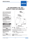
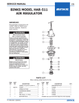
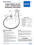
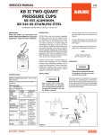
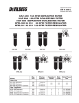
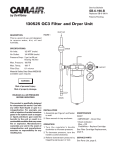
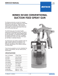
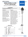
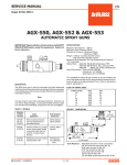
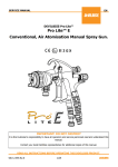
SERVICE MANUAL
HFRL-508 60 CFM
FILTER-REGULATOR
HAF-502 100 CFM FILTER
IMPORTANT:
Read and follow all instructions and SAFETY PRECAUTIONS before
using this equipment. Retain for future reference.
Risk of personal injury.
Risk of property damage.
Except as otherwise specified by the manufacturer, this
product is specifically designed for compressed air service
and use with any other fluid (liquid or gas) is a misapplication. For example, use with or injection of certain
hazardous gases in the system (such as oxygen or liquid
petroleum gas) could be harmful to the unit or result in a
combustible condition that may cause fire or explosion.
Manufacturer’s warranties are void in the event of misapplication and manufacturer assumes no responsibility for
any resulting loss.
DESCRIPTION
This 100 CFM filter (Model HAF-502) is designed to remove dirt, pipe
scale and most liquid aerosol. It includes a 5 micron filter element. A
model with 50 CFM air regulator is also available (Model HFRL-508).
Specifications
Air Filter:
Air Inlet
Air Outlet
Air Flow Capacity
Maximum Temp.
Max. Inlet Pressure
Max. Operating Pressure
Air Connections Model HFRL-508:
Regulated
(1) 1/4" NPS(M)
(1) Plugged Port
1/2" NPT(F)
1/2" NPT(F)
100 CFM
150° F (65.6° C)
150 psig (10.3 bar)
150 psig (10.3 bar)
Non-Regulated
(1) 1/4" NPS(M)
INSTALLATION
Risk of injury. Release all air pressure from system
before servicing system. Do not place unit in service without metal bowl guard installed. Plastic bowl
units are sold only with metal bowl guards. To minimize the
danger of flying fragments in the event of plastic bowl failure,
guard must not be removed. If the unit is in service without
the metal bowl guard installed, manufacturer's warranties
are void and the manufacturer assumes no responsibility
for a resulting loss. If unit has been in service and does not
have a metal bowl guard, order one and install before placing back in service.
Certain solvents, paints and chemicals may attack plastic bowl
and can cause bowl failure. Do not use near these materials.
SB-6-146-H (12/2014)
1.Be sure to read all "WARNINGS" and "CAUTIONS" in
this manual and on the unit before installation or using this
equipment.
2.Install filter as close as possible to point where air is
being used. Install main air shut-off valve and standard
pipe union (supplied by user) upstream of filter to allow maintenance to unit.
3.Install unit with air flow through filter in direction of arrow on
top of unit.
4.Minimum 1/2" piping is recommended. Avoid using
fittings, couplings, etc. that restrict air flow.
5.A 1/2" street elbow will be needed to allow vertical pipe installation. Mount filter in a vertical position.
6.Do not install filter in an application where the pressure drop
will exceed 20 psi. For example, a quick opening valve located
upstream from the filter could cause a momentary pressure drop
in excess of 20 psi.
7.Install "T" handle into regulator (Model HFRL-508).
8.Maximum inlet pressure and operating temperature is:
150 PSIG (10.3 bar) and 150° F (65.6° C).
9. A 6' length of vinyl tubing is shipped loose with the unit. Slide
over automatic drain which protrudes from bottom of bowl. Place
other end of vinyl tubing into appropriate receptacle (i.e. below
booth grating, can, etc.). Prevent vinyl tubing from becoming
kinked which would prevent free movement of liquids discharged
from the automatic drain.
10.An optional manual drain (HAF-11) is supplied loose in the
carton (see item 10, Fig. 2). If desired, this can be installed
in place of the automatic drain.
OPERATION
After unit is installed and ready to use:
1. Attach air hose(s) to outlet ball valve(s), selecting regulated and/
or non-regulation according to the application.
2. Open main shut-off valve upstream of filter.
3. Main line air pressure is monitored by the top air gauge.
4. Adjust regulator to desired setting by turning "T" handle
in or out.
5. Open ball valve(s) to supply air to spray gun or tool being
used. With air flowing, readjust air pressure at regulator
if necessary.
6. After use, shut off ball valve(s) and bleed off residual air in hose(s).
MAINTENANCE
Certain solvents, paints and chemicals may attack plastic
bowl and can cause bowl failure. Do not use near these materials. When bowl becomes dirty, wipe only with a clean, dry
cloth. Immediately replace any crazed, cracked, damaged or
deteriorated plastic bowl with a new plastic bowl. Reinstall
metal bowl guard.
1. If bowl is equipped with manual drain, drain bowl at least once
per shift. Units with automatic drain will drain automatically.
2. Before performing maintenance on unit, close main
shut-off valve located upstream of filter. Bleed off residual air
in unit.
3. To open filter, press button located on clamp ring and
rotate ring either clockwise or counterclockwise. The metal bowl
guard and plastic bowl can then be removed from the filter head.
1/4
4. Remove the filter element by loosening the baffle counterclockwise. Clean or replace the filter element. The element
can be cleaned by blowing off with a duster gun (clean from
inside out). Frequency of element cleaning/replacement
will depend upon air quality, air usage, and condition of the
air piping. It is recommended to check and clean/replace
the element every 3-6 months.
5. Inspect o-ring (2) for damage. Replace if necessary.
6. Inspect plastic bowl for signs of damage such as cracks,
crazing or deterioration. Replace if necessary. See "Caution"
at beginning of "Maintenance" section, page 1.
Do not place unit in service without metal bowl
guard installed.
7. Before placing unit back into service, make sure plastic
bowl and metal bowl guard are properly installed and securely locked in place.
8. Confirm automatic drain operates properly after unit is in
operation. Replace if necessary.
Note
CA PROP
65
Do not wash plastic bowl with the automatic drain installed.
Water can get into the float mechanism, causing the drain
to malfunction. Remove the automatic drain before cleaning the plastic bowl with soap and water (no solvents).
FIGURE 1 MODEL HFRL-508 FILTER/REGULATOR (60 CFM)
4
3
2
5
1
PARTS LIST – Model HFRL-508
Ref Replacement
No. Part No.
Description
6
7
PROP 65 WARNING
WARNING: This product contains
chemicals known to the State of
California to cause cancer and birth
defects or other reproductive harm.
1
2
3
4
5
6
7
HAF-502
HAF-21
GA-288
83-2727
HAR-507
—
VA-542
Ind.
Parts
Req.
Air Filter, 100 CFM, See Fig.2
Cross Manifold
Air Gauge, 0-160 psi (main line)
Air Gauge, 0-100 psi (regulated)
Air Regulator (See Fig. 3)
1/4" Street Elbow, 90°
Ball Valve
1
1
1
1
1
1
2
PARTS LIST - Model HAF-502
FIGURE 2 MODEL HAF-502 FILTER (100 CFM)
10
(Optional)
Ref Replacement
No. Part No.
Description
1
5
2
4
6
1 —
2 —
3 HAF-26
4 HAF-6
5 HAF-18
6 HAF-8
7 HAF-19
8 HAF-409
9 —
10 HAF-11
Ind.
Parts
Req.
Cover
O-Ring
Baffle Kit
Filter and O-Ring Kit
Automatic Drain (Std.)
Plastic Bowl
Metal Bowl Guard
Clamp Ring
1/2 x 3/8 Vinyl Tubing, 6 ft.
Manual Drain (Optional,
shipped loose)
1
1
1
1
1
1
1
1
1
1
3
7
8
9
2/4
SB-6-146-H (12/2014)
FIGURE 3 HAR-507 AIR REGULATOR, 60 CFM
PARTS LIST - Model HAR-507 Regulator Assembly
Ref Replacement No. Part No.
Description
1
---
2
HAR-14
3
---
4
---
5
---
6
---
7
---
8
KK-4977
9
---
10
---
11
---
12
---
13
---
14
---
A
1
2
3
4
9
5
Individual
Parts
Required
#10-32 x 9/16 Fillister
Hd. Screw
Cover
Spring Button
Diaphragm Spring
Body
Pipe Plug 1/4" NPT(M)
Bottom Plug
Repair Kit (includes Items 9 thru 14)
Diaphragm Assembly
O-Ring
Valve
O-Ring
Spring
O-Ring
6
1
1
1
1
1
1
1
1
1
1
1
1
1
REGULATOR MAINTENANCE
6
10
11
12
13
14
8
1. Occasionally remove bottom plug (7) and clean valve seat
(11) and body. Clean parts with denatured alcohol, wipe off
seat and blow out body with compressed air.
2. To disassemble regulator, remove screws, bonnet, spring and
spring button. Diaphragm assembly can now be removed.
3. Check all o-rings for signs of damage. Replace if necessary.
4. Reassemble parts. Center stem of valve in hole of regulator
body. Screw bottom plug into body.
Note
7
Erratic operation or loss of regulation is usually due
to dirt in the valve area and cleaning is necessary. If
cleaning does not correct the problem, replace the items
included in Repair Kit KK-4977. If unit leaks air at A ,
install Repair Kit KK-4977.
ACCESSORIES
HAF-407 BRACKET ASSEMBLY KIT – Used with HAF-502 and HFRL-508.
SB-6-146-H (12/2014)
3/4
WARRANTY POLICY
DeVilbiss products are covered by Finishing Brands one year materials and workmanship limited warranty.
The use of any parts or accessories, from a source other than Finishing Brands, will void all warranties.
For specific warranty information please contact the closest Finishing Brands location listed below.
Finishing Brands reserves the right to modify equipment specifications without
prior notice. DeVilbiss, Ransburg, BGK, and Binks are registered trademarks of
Finishing Brands. ©2014 Finishing Brands. All rights reserved.
DeVilbiss is part of Finishing Brands, a global leader in innovative spray finishing
technologies. For technical assistance or to locate an authorized distributor,
contact one of our international sales and customer support locations below.
USA/Canada
Industrial Finishing
www.devilbiss.com
[email protected]
Tel:1-800-992-4657
Fax:1-888-246-5732
Mexico
Industrial Finishing
www.finishingbrands.com.mx
[email protected]
Tel: 011 52 55 5321 2300
Fax:011 52 55 5310 4790
United Kingdom
www.finishingbrands.eu
[email protected]
Tel: +44 (0)1202 571 111
Fax:+44 (0)1202 573 488
France
www.finishingbrands.eu
[email protected]
Tel: +33(0)475 75 27 00
Fax:+33(0)475 75 27 59
China
www.finishingbrands.com.cn
[email protected]
Tel: +8621-3373 0108
Fax:+8621-3373 0308
Japan
www.ransburg.co.jp
[email protected]
Tel: 081 45 785 6421
Fax:081 45 785 6517
Brazil
www.devilbiss.com.br
[email protected]
Tel: +55 11 5641 2776
Fax:55 11 5641 1256
Germany
www.finishingbrands.eu
[email protected]
Tel: +49 (0) 6074 403 1
Fax:+49 (0) 6074 403 281
Australia
www.finishingbrands.com.au
[email protected]
Tel: +61 (0) 2 8525 7555
Fax:+61 (0) 2 8525 7500
DeVilbiss Automotive Refinishing is part of Finishing Brands, a global
leader in innovative spray finishing technologies. For technical assistance
or to locate an authorized distributor, contact one of our sales and
customer support locations below.
USA/Canada
www.autorefinishdevilbiss.com
[email protected]
Toll Free Tel: 1-800-445-3988
Toll Free Fax:1-800-445-6643
4/4
Mexico
www.autorefinishdevilbiss.com.mx
Toll Free Tel: 1-888-835-6232 USA
SB-6-146-H (12/2014)