1
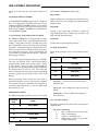
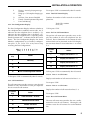
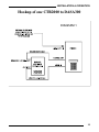
Film-Tech
The information contained in this Adobe Acrobat pdf
file is provided at your own risk and good judgment.
These manuals are designed to facilitate the
exchange of information related to cinema
projection and film handling, with no warranties nor
obligations from the authors, for qualified field
service engineers.
If you are not a qualified technician, please make no
adjuatments to anything you may read about in these
Adobe manual downloads
www.film-tech.com
Copyright 1995 by SMART Devices Inc.
5945 Peachtree Corners East
Norcross, GA 30071-1337
Table of Contents
SECTION 1
INTRODUCTION.........................................................................2
SECTION 2
SMART CTR2000 PHYSICAL DESCRIPTION ...........................2
SECTION 3
INSTALLATION ...........................................................................3
SECTION 4
OPERATION ...............................................................................3
SECTION 5
SYSTEM STATUS, PROGRAMMING & TEST MODES .............4
APPENDIX A
ILLUSTRATIONS FOR SETTING UP CTR2000.........................14
SMART products are designed to deliver unsurpassed quality in workmanship and
performance. The following information gives detailed instructions on the installation
and operation of the SMART CTR2000. We strongly encourage new owners of the
CTR2000 to thoroughly read this entire manual before placing their new SMART
product into service. This will ensure that the CTR2000 will be operated properly to
give the superior performance that it was designed to deliver.
For service or installation assistance, please call our
Technical Support Department between the hours of
8 a.m-5 p.m. E.S.T., Mon.-Fri.
1-800-45-SMART
LIMITED WARRANTY: SMART products and accessories are warranted against malfunction or failure due to defects in workmanship or
materials for a period of one year from the date of shipment. If a problem occurs during the warranty period, the unit will be repaired, or
replaced at our option, without charge for materials or labor. If air freight is requested by the dealer, the difference between air and surface
charges will be billed to the dealer. This limited warranty does not cover products that have been abused, altered, modified, or operated in
other than specified conditions. Prior factory approval is required on all returns. Returned equipment or defective parts must be shipped
freight prepaid to us by the dealer or customer.
Our limited warranty does not cover damages resulting from accident, misuse or abuse, lack of responsible care, or failures not attributable to
manufacturing defects, except as provided herein. SMART Devices, Inc. makes no warranties, express or implied, including warranties of
merchantability or fitness for a particular purpose.
RETURN POLICY: Factory authorization MUST be obtained before returning any product. A 15% restocking charge will be issued on unused
equipment (in original box) that is returned for credit. Credit is issued to the dealer’s account. The credit may be used against future purchases and no cash transactions are offered. All returns must be shipped freight prepaid by the dealer. Equipment returned without a factory RA
(Return Authorization) will be refused.
Installation and Service Manual
CTR2000 Multi-line Concentrator
NOTE: This equipment has been tested and found to
comply with limits for a Class A computing device
pursuant to Subpart J of Part 15 of FCC Rules. These
limits are designed to provide reasonable protection
against harmful interference when this equipment is
operated in a commercial environment. This equipment generates, uses, and can radiate radio frequency
energy and, if not installed and used in accordance
with the instruction manual, may cause harmful
interference to radio communications. Operation of
this equipment in a residential area is likely to cause
harmful interference in which case the user will be
required to correct the interference at his/her own
expense.
Billing Delay for 800/900 Call Counts
This manual Copyright SMART Devices, Inc. All
rights reserved. No part of it may be copied, photocopied, reproduced, translated, or reduced to any
electronic medium or machine readable form without
SMART’s prior written consent.
Free Run Announcers or Controllable
Announcers
Individual Line Enable/Disable Configuration
Each Line may be configured as On, Off or
Timed separately for each day of the week
Time of Day Clock
Programmable Number of Rings (1,2,4,8)
Expansion beyond 8 lines
2 Port Line Cards
2. SMART CTR2000 Physical Description
2.1 Front Panel
Information contained herein is subject to change
without prior notification. SMART Devices, Inc. provides this manual without warranty of any kind,
expressed or implied. This user's manual may contain technical and/or typographical errors.
SYSTEM DATA REPORTING
The 2 Line by 20 character LCD display.
PROGRAMMING ENTRY
Printed in the U.S.A.
1.
Introduction
The SMART CTR2000 is a Multi Line Telephone
Answering System designed to operate with a variety
of SMART Digital Audio Announcement Systems.
SMART CTR2000 when combined with a digital
announcer services up to 8 incoming telephone lines.
The SMART CTR2000 contains the following features:
The Keypad is a 20 button keypad arranged in a 4 by
5 matrix. Keys defined as follows;
Key:
Definition:
I.
Function Key 1 Context dependent key used
in conjunction with the LCD.
II.
Function Key 2 Context dependent key used
in conjunction with the LCD.
III.
Function Key 3 Context dependent key used
in conjunction with the LCD.
IV.
Function Key 4 Context dependent key used
in conjunction with the LCD.
0–9
Numeric Entry Keys
*
Special Function Key
#
Special Function Key
Per Line Call Counters (9999 maximum)
Totalized Call Counts (999999 maximum)
Disconnect – CPC and call duration (01 to 59 )
Individual Line Status
Timed Operation Start Time / Stop Time
Separate Start and Stop time for each day of the
week
2
INSTALLATION & OPERATION
MODE Special Function Key to Enter the
Program, Status or Test Mode
phone line from the telephone line terminating block
to LINE 1 – 8.
CLR
3.1 Digital Announcer Connection
General Purpose Key which is used
to exit or cancel selected functions
2.2 Side Panel Controls and Connections
12 VDC
To connect the external DC power pack.
POWER
The SMART CTR2000 operates in two separate
modes depending upon the specific type of digital
announcer attached. Control mode allows the
SMART CTR2000 to start and stop the digital
announcer for the purpose of providing the first
caller the convenience of hearing the message play
from the beginning, while additional callers enter the
message in play. Control mode requires a digital
announcer capable of external start/stop operation.
This switch enables external power to the system.
AUDIO IN
This connector provides input from the Digital
Announcer.
LCD CONTRAST
Adjusts the contrast of the LCD display to compensate for lighting variations.
CONTROL OUT
Interface to control the play operation of the Digital
Announcer.
Free run mode allows the SMART CTR2000 to operate with any digital announcer. In free run mode, all
callers enter the message in play.
3.2 Audio Level Adjustment
To adjust the message audio level, record the message into the digital announcer following the instructions for the announcer used. Connect an audio cable
from the audio output of the digital announcer to the
Audio In connector of the SMART CTR2000. Place a
call to the SMART CTR2000, while listening to the
announcement, adjust the audio out level from the
digital announcer. In compliance with FCC regulations, the SMART CTR2000 limits amount of audio
signal level present to the telephone line.
CONTROL IN
4. Operation
Expansion port for connecting more than one SMART
CTR2000 to a single Digital Announcer.
LINE 1–8
Modular telephone connector for connecting telephone lines to the SMART CTR2000.
3. Installation (See illustrations in Appendix A)
Locate the SMART CTR2000 within 6 feet of a 110
VAC outlet. The SMART CTR2000 can be either wall
or desktop mounted. When locating, be sure to leave
clearance room on the left side for connection and
adjustments.
Connect the DC power pack supplied with the system to the 12 VDC power connection on the left side
of the unit and plug the power pack into a 110 VAC
outlet.
Connect a modular telephone cable for each tele-
4.1 Controllable Announcers
The first call answered by the unit starts the Digital
Announcer. As other calls are answered, they are
connected to the announcement in progress. As long
as the caller remains on the line, the announcement
will continue to play until the maximum call hold
time has been reached. As each caller hangs up, the
line become immediately available to answer another
call. When all of the lines return to the idle state, the
Announcer is stopped.
4.2 Other Announcers
When operating in a free run, continuous play mode.
Each call answered is connected to the announcement
in progress. As long as the caller remains on the line,
the announcement will continue to play until the
maximum call hold time has been reached. As each
caller hangs up, the line become immediately available to answer another call. When all of the lines
3
SRS-3 STEREO PROCESSOR
return to the idle state, the Announcer continues to
run.
three SMART CTR2000 functional modes;
Status Mode:
4.3 Multiple SMART CTR2000's
A single SMART CTR2000 supports up to 8 telephone
lines. For applications requiring more than 8 lines,
additional SMART CTR2000 systems can be added.
A special cable allows the audio and control signals
from the first SMART CTR2000 to be extended to the
second SMART CTR2000.
5. System Status, Programming and Test Modes
The SMART CTR2000 may be programmed to fit the
user's application needs. Programmable functions
include; setting time and date, call hold time, number of rings before answer, call count delay and timed
operation. All programming and configuration parameters are stored in non volatile memory for protection again power outages. Once programmed, the
system needs no further attention unless a programming change is desired.
To access the programming functions, press "MODE".
The user is presented with a "Mode Select Menu"
which presents options for accessing "Status", "Prog"
or "Test" modes. The user selects a specific mode by
pressing the corresponding Function Key (I,II,III,IV).
The Function keys are used as "soft" keys where the
action associated with those keys changes depending
upon the specific text presented on line 2 of the LCD
Display.
When presenting a menu where the user selects a
specific Function key, Line 2 of the LCD is sectioned
into 4 blocks where the first block of 5 characters is
associated with Function key "I", the next block with
Function key "II", etc.
Display information concerning the current line condition, call counts and enabling or disable individual
telephone lines.
Prog Mode:
Setting system operating parameters, number of
rings, billing delay time, setting Time and Date, call
hold time and timed operation.
Test Mode:
System self tests for diagnostic purposes.
5.1 Status Mode Menu
Status Mode provides access to the following functions;
Function
Key
Action
I
Line State
II
Line Configuration
III
Call Count
IV
Clear (exit)
Line State – Current status of each individual
tele phone line
Line Conf – Line Configuration per day (On, Off,
Timed)
MODE SELECT MENU
The Mode Select Menu provides access to one of the
Function
Key
Action
I
Status Mode
II
4
III
Program Mode
IV
Test Mode
Call Counts – Total and individual telephone
line call counts
5.1.1 Line State Display
The display indicates the current state of each of the 8
telephone lines.
Line State
I
R
A
D
Definition
Idle – On Hook ready to answer calls
Ring – Line Ringing
Answer – Answering Call
Billing Delay – Waits 1 or 16 seconds
before counting call
INSTALLATION & OPERATION
P
H
O
T
—
Playing – Actively playing message
to caller
Hang up – Call complete hanging up
line
Off Line – Line Answer Disabled
Timed – Timed Operation Off period
Line Card Missing
To exit press "CLR" or automatically after 15 seconds
5.1.3.1 Total Call Count Display
Totalizes the number of calls received on each telephone line.
Total Calls = 999999
Press (Clr)
5.1.2 Line Configuration Display
The Line Configuration Display indicates whether or
not a telephone line is enabled to answer calls. An "I"
indicates that the telephone line is enabled, a "O"
indicates that the telephone line is disabled, a "T"
indicates that the telephone line is operating under
Timed Operation and " " indicates that the line card is
absent. The Line Configuration Display first shows
Monday's configuration, to see Tuesday's configuration press "I", etc. Press "Clr" at any time to stop
reviewing the Line Configurations.
Mon = 1 2 3 4 5 6 7 8
(Tue) T I I T T O – –
Function
Key
Action
I
Next Day
To Exit press "CLR"
5.1.3.2 Per Line Call Count Menu
The per line call count menu provides access to display the number of calls each telephone line has
received. Due to limitations in the amount of information which can be presented on the LCD display,
the user must choose to view either lines 1 – 4 or lines
5 – 8.
Function
Key
Action
I
Display call counts 1 – 4
II
Display call counts 1 – 4
III
Display call counts 5 – 8
IV
Display call counts 5 – 8
II
III
IV
Exit Line Configuration Review
To Exit press "CLR" or automatically after 15 seconds
5.1.3.2.1 Lines 1 – 4 Call Counts
To Exit press "CLR" or automatically after 15 seconds
Displays total number of calls received on lines 1 – 4.
5.1.3 Call Count Menu
To exit press "CLR"
The call count menu provides access to view the total
number of calls, the number of calls per telephone
line or to reset the call counters.
5.1.3.2.2 Lines 5 – 8 Call Counts
Displays the number of call received on lines 5 – 8.
Function
Key
Action
I
Total call count – all lines
II
Individual line call count
III
RESET call count
IV
Exit menu
To exit press "CLR"
5.1.3.3 Reset Call Count Menu
The reset call count menu provides the user a confirmation for reset the call counters. Clearing the call
counters resets the call counters for each individual
line.
5
CTR2000 CONCENTRATOR
digit is a "1" then the units digit may be (0 2).
Function
Key
Action
I
Yes – Clears count ALL lines
II
Valid Keys (0 – 9)
III
IV
Enter Month?
01/05/95
09:30:32 AM
Clr – Advance to Day without making change
No – Exit no change in call counts
To Exit – Automatically after 15 seconds
To Exit press "CLR" or automatically after 15 seconds
5.2.1.2 Set Time and Date – Enter Day (tens digit)
5.2 Programming Mode Menu
Entering the day, the system checks that the day
entered is valid between 01 and 31. The tens digit
must be between "0 – 3".
The Programming Mode provides access to setting
the time and date and system configuration parameters.
Enter Day?
01/05/95
09:30:32 AM
Function
Key
Action
I
Set time and date
Clr – Advance to Year without making change
II
Set time and date
To Exit – Automatically after 15 seconds
5.2.1.3 Set Time and Date – Enter Day (units digit)
III
IV
Valid Keys (0-3)
Change system configuration
To Exit press "CLR" or automatically after 15 seconds
5.2.1 Set Time and Date – Enter Month (tens digit)
Entering the day, the system checks that the day
entered is valid between 01 and 31.
Enter Day?
01/05/95
09:30:32 AM
Valid Keys (0 – 9)
Entering the month, the system checks that the month
entered is valid between 01 and 12. The tens digit
may only be a "0" or a "1".
Enter Month?
01/05/95
09:30:32 AM
Valid Keys (0,1)
Clr Advance to Day without making change
Clr – Advance to Year without making change
To Exit – Automatically after 15 seconds
5.2.1.4 Set Time and Date – Enter Year (tens digit)
E n t e r Ye a r ?
01/05/95
09:30:32 AM
To Exit – Automatically after 15 seconds
Valid Keys (0 – 9)
5.2.1.1 Set Time and Date – Enter Month (units
digit)
Clr – Advance to Hour without making change
To Exit – Automatically after 15 seconds
Entering the month, the system checks that the month
entered is valid between 01 and 12. If the tens digit is
a "0" then the units digit may be (1 – 9), if the tens
6
INSTALLATION & OPERATION
5.2.1.5 Set Time and Date – Enter Year (units digit)
E n t e r Ye a r ?
01/05/95
09:30:32 AM
Valid Keys (0 9)
either AM or PM.
To Exit – Press "CLR" or automatically after 15 seconds
5.2.1.9 Set Time and Date – Enter Minutes (tens
digit)
Clr – Advance to Hour without making change
To Exit – Automatically after 15 seconds
5.2.1.6 Set Time and Date – Enter Hour (tens digit)
Entering the hour, the system checks that the hour
entered is valid between 00 and 12. The tens digit
may only be a "0" or a "1".
Enter Hour?
01/05/95
09:30:32 AM
Entering the minutes, the system checks that the minutes entered is valid between 00 and 59. The tens
digit may be between "0 5".
Enter Minutes?
01/05/95
09:30:32 AM
Valid Keys (0 – 5)
Clr – Advance to Second without making change
To Exit – Automatically after 15 seconds
Valid Keys (0 – 1)
Clr – Advance to Minute without making change
To Exit – Automatically after 15 seconds
5.2.1.7 Set Time and Date – Enter Hour (units digit)
Entering the hour, the system checks that the hour
entered is valid between 00 and 12.
Enter Hour?
01/05/95
09:30:32 AM
5.2.1.10 Set Time and Date – Enter Minutes (units
digit)
Entering the minutes, the system checks that the minutes entered is valid between 00 and 59.
Enter Minutes?
01/05/95
09:30:32 AM
Valid Keys (0 – 9)
Clr – Advance to Second without making change
Valid Keys (0 – 9)
To Exit – Automatically after 15 seconds
Clr – Advance to Minute without making change
5.2.1.11 Set Time and Date – Enter Seconds (tens
digit)
To Exit – Automatically after 15 seconds
5.2.1.8 Set Time and Date – Enter AM or PM
After the hour is entered, the user is asked to select
Function
Key
Action
I
Selects AM
Entering the seconds, the system checks that the seconds entered is valid between 00 and 59. The tens
digit may be between "0 5".
Enter Seconds?
01/05/95
09:30:32 AM
Valid Keys (0 5)
II
Clr – Advance to Day of Week without making
change
III
To Exit – Automatically after 15 seconds
IV
Selects PM
7
CTR2000 CONCENTRATOR
5.2.1.12 Set Time and Date – Enter Seconds (units
digit)
Entering the seconds, the system checks that the seconds entered is valid between 00 and 59.
Enter Seconds?
01/05/95
09:30:32 AM
Valid Keys (0 9)
Clr – Advance to Day of Week without making
change
Delay and Timed Operation. Prior to entering the
change configuration mode, the user is asked to confirm.
To Exit – Press "CLR" or automatically after 15 seconds.
5.2.2.1 Call Hold Time Menu
Call Hold Time is the maximum amount of time that
a caller is allowed to remain on the line before the
system will terminate the call. The call hold time
should be selected to allow the caller the opportunity
to hear the complete message.
To Exit – Automatically after 15 seconds
Function
Key
Action
I
Accepts current hold time
5.2.1.13 Set Day of Week
While the system contains a clock calendar, it needs
to by informed of the current day of week when programming the Time and Date.
II
III
Function
Key
Action
I
Accepts the displayed Day of Week
II
To change hold time
To Exit – Press "CLR" or automatically after 15 seconds
5.2.2.1.1 Change Call Hold Time – Enter Minutes
(tens digit)
III
IV
IV
Advances to the next Day of Week
Entering the minutes, the system checks that the minutes entered is valid between 00 and 59. The tens
digit may be between "0 – 5".
Valid Keys ( )
Valid Keys (0 – 5)
To Exit – Automatically after 15 seconds
5.2.2 System Configuration Change Menu
To Exit – Press "CLR" or automatically after 15 seconds
The configuration change menu provides access for
modifying; Call Hold Time, Number of Rings, Billing
5.2.2.1.2 Change Call Hold Time – Enter Minutes
(units digit)
Function
Key
Action
I
Enter configuration change mode
II
8
Valid Keys (0 – 9)
To Exit – Press "CLR" or automatically after 15 seconds
III
IV
Entering the minutes, the system checks that the minutes entered is valid between 00 and 59.
Exit configuration change mode
INSTALLATION & OPERATION
5.2.2.2 Set Number of Rings Menu
The set number of rings menu allows the user to
select the number of rings that will occur prior to the
system answering the telephone call.
Function
Key
Action
I
Advances to timed operation programming
II
Function
Key
Action
I
Number rings before answering =1
III
IV
Skips timed operation without making
changes
II
Number rings before answering =2
III
Number rings before answering =4
To Exit – Press "CLR" or automatically after 15 seconds
IV
Number rings before answering =8
5.2.2.5 Timed Programming – Everyday
To Exit – Press "CLR" or automatically after 15 seconds
5.2.2.3 Billing Delay Time Selection Menu
Billing delay is useful for 800 and 900 type applications where the telephone call is paid for by either the
caller or the user. Billing delay ensures that the call is
not counted unless the length of the call exceeds the
delay period (1 second or 16 seconds).
Enables the entry of Start and Stop time which will be
applied to every day of the week.
Function
Key
Action
I
Programs the same start & stop times
for each day
II
III
Function
Key
Action
I
Sets billing delay to 1 second
II
Advances to the next programming
selection
To Exit – Press "CLR" or automatically after 15 seconds
5.2.2.6 Timed Programming – Monday through
Friday
III
IV
IV
Sets billing delay to 16 seconds
To Exit – Press "CLR" or automatically after 15 seconds
Enables the entry of Start and Stop time which will be
applied to weekdays (Monday Friday).
Function
Key
Action
I
Programs the same start & stop times
for weekdays
5.2.2.4 Timed Operation Menu
Under timed operation, the system will only answer
calls after the start time and until the stop time for the
specified Day of Week. Call received during the
"Timed" period receive a ring no answer. Start times
and stop times may be set to any value from start in
the morning, stop in the evening to start in the
evening, stop in the morning. The start and stop
times should then be reviewed to ensure that they are
the desired hours of operation.
II
III
IV
Advances to the next programming
selection
To Exit – Press "CLR" or automatically after 15 seconds
9
CTR2000 CONCENTRATOR
5.2.2.7 Timed Programming – Saturday and Sunday
Enables the entry of Start and Stop time which will be
applied to weekends (Saturday and Sunday).
Function
Key
Action
I
Programs the same start & stop times
for weekends
To Exit – Press "CLR" or automatically after 15 seconds
5.2.2.9.1 Change Answer Start Time – Enter Hour
(tens digit)
Entering the hour, the system checks that the hour
entered is valid between 00 and 12. The tens digit
may only be a "0" or a "1".
Enter Hour?
08:30 AM
II
III
IV
Advances to the next programming
selection
To Exit – Press "CLR" or automatically after 15 seconds
Valid Keys (0 – 1)
To Exit – Press "CLR" or automatically after 15 seconds
5.2.2.8 Timed Programming – Individual Days
5.2.2.9.2 Change Answer Start Time – Enter Hour
(units digit)
Enables the entry of Start and Stop time which will be
applied to each individual day of the week.
Entering the hour, the system checks that the hour
entered is valid between 00 and 12.
Function
Key
Action
I
Programs the same start & stop times
for each day
II
Enter Hour?
08:30 AM
Valid Keys (0 9)
To Exit – Press "CLR" or automatically after 15 seconds
III
IV
Advances to the next programming
selection
To Exit – Press "CLR" or automatically after 15 seconds
5.2.2.9 Time to Start Answering Calls
The currently programmed time to begin answering
calls is shown. To change that time, Press "IV" (No),
if no change is desired, Press "I" (Yes).
5.2.2.9.3 Change Answer Start Time – Enter AM or
PM
After the hour is entered, the user is asked to select
either AM or PM.
Function
Key
Action
I
Selects AM
II
Function
Key
Action
I
Accepts answer start time
II
10
IV
Selects PM
To Exit – Press "CLR" or automatically after 15 seconds
III
IV
III
To change answer start time
INSTALLATION & OPERATION
5.2.2.9.4 Change Answer Start Time – Enter
Minutes (tens digit)
Entering the minutes, the system checks that the minutes entered is valid between 00, 15, 30, and 45. The
CTR2000 will not accept any other time except those
listed above.
Enter Minutes?
08:30 AM
may only be a "0" or a "1".
Enter Hour?
08:30 AM
Valid Keys (0 – 1)
To Exit – Press "CLR" or automatically after 15 seconds
Valid Keys (0 – 5)
5.2.2.10.2 Change Answer Stop Time – Enter Hour
(units digit)
To Exit – Press "CLR" or automatically after 15 seconds
Entering the hour, the system checks that the hour
entered is valid between 00 and 12.
5.2.2.9.5 Change Answer Start Time – Enter
Minutes (units digit)
Enter Hour?
08:30 AM
Entering the minutes, the system checks that the minutes entered is valid between 00, 15, 30 and 45.
Enter Minutes?
08:30 AM
Valid Keys (0 – 9)
To Exit – Press "CLR" or automatically after 15 seconds
Valid Keys (0 – 9)
5.2.2.10.3 Change Answer Stop Time – Enter AM or
PM
To Exit – Press "CLR" or automatically after 15 seconds
After the hour is entered, the user is asked to
select either AM or PM.
5.2.2.10 Time to Stop Answering Calls
The current time to stop answering calls is shown. To
change that time, Press "IV" (No), if no change is
desired, Press "I" (Yes).
Function
Key
Action
I
Accepts answer stop time
II
Function
Key
Action
I
Selects AM
II
III
Selects PM
IV
To Exit – Press "CLR" or automatically after 15 seconds
III
IV
To change answer stop time
To Exit – Press "CLR" or automatically after 15 seconds
5.2.2.10.1 Change Answer Stop Time – Enter Hour
(tens digit)
Entering the hour, the system checks that the hour
entered is valid between 00 and 12. The tens digit
5.2.2.10.4 Change Answer Stop Time – Enter
Minutes (tens digit)
Entering the minutes, the system checks that the minutes entered is valid between 00 and 59. The tens
digit may be between "0 5".
Enter Minutes?
07:30 PM
Valid Keys (0 – 5)
11
CTR2000 CONCENTRATOR
To Exit – Press "CLR" or automatically after 15 seconds
5.2.2.10.5 Change Answer Stop Time – Enter
Minutes (units digit)
Entering the minutes, the system checks that the minutes entered is valid between 00 and 59.
Enter Minutes?
07:30 PM
Function
Key
Action
I
To change Monday’s line config.
II
III
To advance to Tuesday’s line config.
IV
Valid Keys (0 – 9)
To Exit – Press "CLR" or automatically after 15 seconds
5.2.2.11 Change Line Configuration
Each individual line may be configured as "On", "Off"
or "Timed" each day of the week. Under timed operation, the system will only answer calls after the start
time and until the stop time for the specified Day of
Week. Call received during the "Timed" period
receive a ring no answer. Start times and stop times
may be set to any value from start in the morning,
stop in the evening to start in the evening, stop in the
morning.
5.2.2.11.2 Change Line Configuration – Tuesday
Function
Key
Action
I
To change Tuesday’s line config.
II
III
IV
To advance to Wednesday’s line config.
Valid Keys (0-9)
To change the configuration of an individual line,
press the corresponding line number. For example,
to change line 1 from "T" Timed to "O" Off, press "1".
To change line 1 to "I" On Idle, press "1" again, etc.
To Exit – Press "CLR" or automatically after 15 seconds
5.3 Test Mode
Function
Key
Action
I
Enters the line programming menu
– Software Version Information
– Key Pad Test
– LCD Test
– Non volatile Memory Test
II
III
IV
Test mode provides access to verify the basic integrity of the SMART CTR2000. Included in the test mode
functions are;
Exits the programming menu
Function
Key
Action
To Exit – Press "CLR" or automatically after 15 seconds
I
Display software revision number
5.2.2.11.1.1 Change Line Configuration – Monday
II
Test the key pad
Valid Keys (1 – 8) Corresponding to the line number
III
Test LCD Display
To Exit – Press "CLR" or automatically after 15 seconds
IV
Test nonvolatile memory
12
INSTALLATION & OPERATION
To Exit – Press "CLR" or automatically after 15 seconds
5.3.1 Software Version
The software version information provides useful
information for customer support and new feature
additions.
S o f t w a r e Ve r s i o n X . X
To Exit – Press "CLR"
5.3.2 Key Pad Test
This test ensures that the key pad is working properly
and that the key caps are properly labeled. The key is
displayed as long as it is depressed. The "Clr" key is
never displayed but resulting in exiting the key pad
test.
K e y Te s t , C l r t o E n d
Key Pressed =
To Exit – Press "CLR"
5.3.3 LCD Test
The LCD Test is an alternating display where one line
contains text, and the only is solid black.
L C D Te s t , C l r t o e n d
To Exit – Press "CLR"
5.3.4 Nonvolatile Memory Test
System configuration parameters and call counts are
stored in non volatile memory. This test ensures that
the non volatile memory retention battery is within
acceptable limits.
M e m o r y D e v i c e Te s t
Memory Passed!
M e m o r y D e v i c e Te s t
Memory Failed!
To Exit – Press "CLR"
13
CTR2000 CONCENTRATOR
APPENDIX A
Diagram 1 (page 15): Hookup for one
CTR2000 to DASA300.
Diagram 2 (page 16): Hookup for multiple CTR2000’s to DASA300.
Notes for both diagrams:
1) All CTR2000 “Control” terminals
require 8-pin din connectors.
2) The Remote Start cable is an 8-pin
din to 1/8” mini-jack cable.
3) The DASA300 MUST BE a looping
version unit. If not, then an internal
EPROM may be ordered from the factory that will make the unit compatible with the CTR2000.
14
INSTALLATION & OPERATION
Hookup of one CTR2000 to DASA300
DIAGRAM 1
15
CTR2000 CONCENTRATOR
Hookup for multiple CTR2000’s to DASA300
DIAGRAM 2
16