1
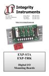
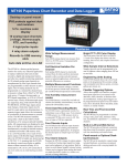
The way PC-based instrumentation should be
DI-161
Event, State, and Count Data Logger
User's Manual
Manual Revision A
Copyright © 2014 by Dataq Instruments, Inc. The Information contained herein is the exclusive property of Dataq Instruments, Inc.,
except as otherwise indicated and shall not be reproduced, transmitted, transcribed, stored in a retrieval system, or translated into any
human or computer language, in any form or by any means, electronic, mechanical, magnetic, optical, chemical, manual, or otherwise
without expressed written authorization from the company. The distribution of this material outside the company may occur only as
authorized by the company in writing.
Dataq Instruments' hardware and software products are not designed to be used in the diagnosis and treatment of humans, nor are
they to be used as critical components in any life-support systems whose failure to perform can reasonably be expected to cause significant injury to humans.
241 Springside Drive
Akron, Ohio 44333 U.S.A.
Telephone: 330-668-1444
Fax: 330-666-5434
Designed and manufactured in the
United States of America
DI-161 OEE Event, State, and Count Data Logger
Introduction
Congratulations on your purchase of the DI-161 LAN-based OEE (Overall Equipment Effectiveness) Event,
State, and Count Data Logger. This documentation is designed to familiarize you with the features and functions of the Hardware and Software for the DI-161 OEE Data Logger.
The DI-161 features programmable capture modes to detect events (when events happen), states (how long
between events), and counts (how many events). An internal real-time clock provides time- and date-stamping for each captured quantity. Storage is accomplished to any locally accessible server or database via the
built-in Ethernet interface. The default data storage format is comma-separated value (CSV) so recorded files
are human-readable and easily imported to other applications like Microsoft Excel. Alternately, data may be
stored directly to a locally accessible MSSQL database.
The DI-161 features eight input channels designed specifically for an isolated switch module that allows detection of any signal amplitude, from 10 to 280 Vrms or Vdc (dependant upon model). Modules may be mixed and
matched on a channel-by-channel basis. Channel status LEDs provide instant visual feedback for channel
activity.
The DI-161 also provides 8 socketed fuses (one per channel) for input module protection. Fuses are easily
removable and replaced.
Learn more about the DI-161 Hardware
Learn more about the DI-161 Event Recorder Software
2
DI-161 OEE Event, State, and Count Data Logger
Warranty and Service Policy
Product Warranty
DATAQ Instruments, Inc. warrants that this hardware will be free from defects in materials and workmanship
under normal use and service for a period of one year from the date of shipment. DATAQ Instruments' obligations under this warranty shall not arise until the defective material is shipped freight prepaid to DATAQ
Instruments. The only responsibility of DATAQ Instruments under this warranty is to repair or replace, at its
discretion and on a free of charge basis, the defective material.
This warranty does not extend to products that have been repaired or altered by persons other than DATAQ
Instruments employees, or products that have been subjected to misuse, neglect, improper installation, or
accident. DATAQ Instruments shall have no liability for incidental or consequential damages of any kind arising out of the sale, installation, or use of its products.
Service Policy
1. All products returned to DATAQ Instruments for service, regardless of warranty status, must be on a
freight-prepaid basis.
2. DATAQ Instruments will strive to achieve a 5 day turnaround on any repair or replacement of any defective
product.
3. For in-warranty repairs, DATAQ Instruments will return repaired items to the buyer freight prepaid. Out of
warranty repairs will be returned with freight prepaid and added to the service invoice.
3
DI-161 OEE Event, State, and Count Data Logger
Hardware
Features
Model DI-161 is a data logging device for overall equipment effectiveness (OEE) metrics that yields accurate
and timely information related to machine-based process efficiency. The instrument applies one of three
modes to automate the measurement of process activity:
l
l
l
Events – when something happened
States – how long something happened
Counts – how many happened
Applied in combination to any process evaluation task, these three basic modes develop a complete picture
that describes all the variables you need to quantify OEE:
l
l
l
l
Actual operating time
Actual production rate
Total units produced
Defective units produced
Features include:
l
l
l
l
l
l
Eight configurable channels
Built-in Ethernet interface (connect via your LAN)
Flexible report interval of once every second to once every day
Reports a date and time stamp with each interval
Eight easily replaceable socketed fuses for voltage protection
DIN rail and rack for easy installation
Signal Inputs
The DI-161 features eight channels designed specifically for signal conditioning modules and connects to any
signal type from 10 to 280 Vrms/DC. Each channel may be configured to detect an event, state, or count on
either the rising or falling edge.
4
DI-161 OEE Event, State, and Count Data Logger
Specifications
Signal Inputs
Number of Input Channels: 8
Input channel range: refer to module specs
Channel-to-channel Isolation: 600 VDC or peak AC
Input-to-output Isolation: 600 VDC or peak AC
AC/DC module detailed specifications
Model
Input:
IN5S
IA5S
IM5S
Nominal Input Voltage 1
24
120
240
Minimum Input Voltage 1
10
80
90
Maximum Input Voltage 1
60
140
280
Maximum Input Current
30
10
8
Drop Out Current
1.0
2.5
1.5
Allowable Off-state Current
1.0
3.0
2.0
Allowable Off-state Voltage
2.0
50
120
Units
Vrms/Vdc
mA rms
Vrms/Vdc
Output:
Maximum Turn-on Time (Vac)
20
Maximum Turn-off Time (Vac)
30
Maximum Turn-on Time (Vdc)
1
Maximum Turn-off Time (Vdc)
1
msec
Line Frequency Range
50-60
Maximum DC Pulse Count Frequency
50
Maximum AC Line Pulse Count Frequency
25
1 Unipolar only
Hz
for DC input signals. AC input signals support line frequencies (50-60 Hz)
DC module detailed specifications
Model
5
DI-161 OEE Event, State, and Count Data Logger
Input:
IB5S
Units
Nominal Input Voltage 2
24
Minimum Input Voltage 2
3.3
Maximum Input Voltage 2
32
Maximum Input Current
32
mA dc
Nominal Input Resistance
1K
Ohm
Drop Out Current
1.0
Allowable Off-state Current
1.0
Allowable Off-state Voltage
2.0
Vdc
mA dc
Output:
Maximum Turn-on Time
5
Maximum Turn-off Time
5
msec
Maximum DC Pulse Count Frequency
2 Unipolar signals
100
Hz
only
Internal Clock
Accuracy: 20 ppm
Sync method: Via connected PC during setup
System Configuration
Method: Using PC-based program and web server via Ethernet interface
Parameters: Measurement configuration; sampling interval; network settings; channel
labels
Programmable network set- DHCP/fixed/DNS IP address; subnet mask
tings:
Measurement Operation
Programmable func- Event, State, Count; positive- or negative-edge triggering
tions (per channel):
Counter Operation
Counts the number of events occurring over a sample interval.
Reset condition: Programmable interval timeout
Maximum count: 8,640,000
6
DI-161 OEE Event, State, and Count Data Logger
Maximum frequency: (See module specifications)
Minimum pulse width: (See module specifications)
State operation
Determines the DURATION of an event. Records the state that exists upon termination of a sample interval.
Event operation
Determines WHEN an event occurred, but does not yield the duration of the event.
Records a single time-stamped data point when one or more events occur within a
definable interval.
Minimum pulse width: 5 mSec
Programmable Inter- .1 to 86,400.0 seconds(.1 sec to 1 day).
vals (applies to all
channels):
Controls, Indicators, and Connections
Interface: Ethernet (operation); USB (firmware upgrades)
Channel Indicators Channel state (true/false), one per channel
(LED):
Active Indicator Indicates activity: Flashes 3 times per second when program running; once per sec(LED): ond otherwise.
Power Indicator Indicates power.
(LED):
Signal input con- Screw terminals, four per channel: ± signal input and (2) no-connect.
nections:
Power connector: 2-position screw terminal
Signal module back- Eight positions (one per channel)
plane:
Fuse socket: Eight positions (one per channel)
Power
Voltage range: 9 to 36 Vdc
Power consumption: 2.25 watts (excluding modules)
Power consumption per module: 0.10 watts
Optional Power Supply (DIN-P24)
Rated input voltage: 100-240 Vac
Input frequency: 47-63 Hz
Inrush current (115/230 Vac): 15/30 A
Efficiency: >80%
Voltage out: 24 Vdc
7
DI-161 OEE Event, State, and Count Data Logger
Nominal current out: 420 mA
Input-to-output isolation: 500 Vdc
Minimum required free space: 25 mm on all sides
Operating temp: -25 to +71 °C
Approval: CE, UL508
Weight: 60g
Environmental
Operating Temperature: 0°C to 35°C (32°F to 95°F)
Operating Humidity: 0 to 90% non-condensing
Storage Temperature: -20°C to 45°C
Storage Humidity: 0 to 90% non-condensing
Physical Characteristics
Mounting and type: DIN rail, EN 50022, top hat rail
Dimensions (with modules): 10.35 x 2.41 x 4.94 inches
Weight (with modules): 1.35 lbs
OS Compatibility
Setup software: Windows XP (32-bit), Windows Vista, 7, 8, and 8.1 (32- and 64-bit versions)
CSV files: OS-independent
8
DI-161 OEE Event, State, and Count Data Logger
Block Diagram
9
DI-161 OEE Event, State, and Count Data Logger
Dimensional Drawing
10
DI-161 OEE Event, State, and Count Data Logger
Unpacking the Device
The following items are included with each DI-161 OEE Event, State, and Count Data Logger. Verify that you
have the following:
l
l
l
l
l
l
Your DI-161 Instrument
1 (one) 6-foot CAT-5 cable
8 (eight) input fuses (pre-installed)
Case and mounting feet (with DI-161 board installed)
DATAQ Instruments screw driver for signal connections
Software via download (http://www.dataq.com/161)
Please note: The DI-161 DOES NOT include input modules or a power supply. These items may be ordered
via the DATAQ Instruments online store.
If an item is missing or damaged, submit a support ticket at http://www.dataq.com/ticket or call DATAQ
Instruments at 330-668-1444. DATAQ support will guide you through the appropriate steps for replacing missing or damaged items. Save the original packing material in the unlikely event that your unit must, for any reason, be sent back to DATAQ Instruments.
11
DI-161 OEE Event, State, and Count Data Logger
Connecting Input Signals
All input signal connections are made to the 20-port screw terminal. Each terminal is labeled directly on the circuit board.
Use the following diagram to connect channel 0.
When an input signal is connected and the DATAQ Instruments Event Recorder software is run, a real time
display of sampled data is shown.
12
DI-161 OEE Event, State, and Count Data Logger
Applying Power
Use the following diagram to properly connect and apply power to the DI-161.
13
DI-161 OEE Event, State, and Count Data Logger
Indicators and Connections
Ethernet Port
Connect the provided 7-foot Ethernet cable to any local network port.
Power LED
Indicates Power is applied to the instrument.
Active LED
Indicates device is recording data.
20-port Screw Terminal Block
Provides all connections for the DI-161 including Ground (GND) and Power (PWR+ and -).
Removable Fuses
Easily removable fuses with plug-in sockets directly on the circuit board.
Module Connections
Plug any of the compatible modules directly onto the circuit board. Easily secured with a built-in screw.
Channel Activity LEDs
Indicates channel is active.
14
DI-161 OEE Event, State, and Count Data Logger
Software
The DI-161 Event Recorder software is included with the purchase of your DI-161 OEE Event, State, and
Count Data Logger via download. Configure channels, sync the clock to your PC, set the sample interval, and
start/stop recording data to a database file.
Install the software via the DATAQ Instruments web site (www.dataq.com/161).
Learn more about the DI-161 Setup utility
Learn more about the DI-161 Logger utility
15
DI-161 OEE Event, State, and Count Data Logger
DI-161 Setup Utility
The DI-161 Setup Utility is used to determine all the DI-161 devices available on your local area network
(LAN) and their IP addresses. You must know the IP address of your device before running the DI-161 Logger
Software. Simply plug the device into your network, then use or allow your router to assign an IP address to
each DI-161 device. Note that you must adjust the IP address of your PC and/or the DI-161 to be on the same
subnet before you can log data. Contact your system administrator for assistance.
MAC Address
Displays the MAC address of the device for identification. The MAC address is printed on the DI-161 label.
Host Name
If your DI-161 is connected to a DNS server, you may create a Host Name for the device.
16
DI-161 OEE Event, State, and Count Data Logger
IP Addr
The IP address of the device. The IP address of the device is required when using the DI-161 Logger software
for successful connection. You may assign an IP address to the device here. You must have the DHCP Enable checkbox unchecked to change the IP address of the device. Please Note: Make sure the IP address you
choose does not cause a conflict with any other device on the network.
Gateway
The Gateway address used by your LAN.
Primary DNS
The IP address of your DNS (if available).
Secondary DNS
The IP address of your secondary DNS (if available).
User ID
Enter a User ID if you wish to password protect the device over the network. The DI-161 has a built-in web
page allowing you to change the network settings of the device (IP address, DNS settings, etc.) without the
DI161 Setup utility. This page may be password protected by using the User ID and the Password fields here.
The default User ID is admin.
Password
Enter a Password if you wish to password protect the device over the network. The DI-161 has a built-in web
page allowing you to change the network settings of the device (IP address, DNS settings, etc.) without the
DI161 Setup utility. This page may be password protected by using the User ID and the Password fields here.
The default Password is admin.
Manufacture Date
Provides the Manufacture Date of the device. The manufacture date is printed on the DI-161 label.
Serial Number
Provides the Serial Number of the device. The serial number is printed on the DI-161 label.
Version
Provides the Hardware revision number.
DHCP Enable Checkbox
Check this box to allow the router to assign the IP address to the device (recommended). This box should be
checked if your router is assigning the IP address (whether static or dhcp). If unchecked, you can assign an IP
address for the device by entering a new address in the IP Addr text box.
Device Selector
Use the arrows to scroll through all the available DI-161 instruments on your local area network.
17
DI-161 OEE Event, State, and Count Data Logger
DI-161 Web Configuration
As an alternative to the DI-161 Setup Utility described above, the DI-161 may be configured from most web
browsers simply by typing it's IP address into the browser's URL bar. Click on the Network Configuration button to change the device IP.
USER ID and PASSWORD parameters are configured using the DI-161 Setup Utility. The default username
is admin. The default password is admin.
The User Name and Password can be changed in the DI161 Setup utility.
18
DI-161 OEE Event, State, and Count Data Logger
You may change the IP address of the device as well as the Host Name (use only if DNS server is available),
Gateway, Subnet Mask, and DNS servers.
Click Save Config to save the settings to the device. Click the Exit (Do Not Save) button to exit the configuration page.
19
DI-161 OEE Event, State, and Count Data Logger
DI-161 Logger Software
Configure your device for acquisition with the DI-161 Logger software. The initial screen shows the current settings of the device and the device state.
Address
Displays the IP address from which you would like to log data. You must verify the correct IP address of the
device and change in the Setup > Settings menu item under the Settings tab. If there is no device at that IP,
you will get the following error message:
Verify the IP address of the device using the DI161 Setup utility or ask your system administrator what the IP
address of the device is. Enter the IP address of the device correctly in the Settings.
Port
The port assigned to DI-161 hardware. Only change if you system administrator specifies the port number.
Channels
20
DI-161 OEE Event, State, and Count Data Logger
The channels from which data will be logged. Change the enabled channels in Setup > Settings under the
Channel tab.
Period in Sec.
Sample interval in seconds. Enter a new sample interval in the Period in Sec. text box in Setup > Settings
under the Settings tab.
Status and Data Window
Note the Device Status in the lower left hand corner of the main panel. When logging data this panel will display the full location of file that data is being written to. Time elapsed will display on the right. The actual data
will display in the main window.
Click on the Stop Logging button to stop the device.
Start/Stop Continuous/Scheduled Logging Button
Click on this button to start/stop logging data. The text displayed in this button will change depending on the
situation and status of your device.
Learn more about:
Settings Tab
Channel Tab
Labels Tab
Database Tab
Schedule
Top
Copyright DATAQ Instruments, Inc.
21
DI-161 OEE Event, State, and Count Data Logger
Settings Tab
IP Addr
Enter the IP address of the device you wish to log data from. If you do not know the IP address of your device,
consult your system administrator or use the DI161 Setup utility to discover it.
Device
Enter a description or device name. For example, if your device is installed near machine 1, you may want to
enter "Machine 1" in the Device textbox.
Port
Enter the port number for your device. Consult your system administrator if different than 23 (default).
Period in Sec.
Enter a sample interval in seconds to set the sample rate of the device. Enter a number from 0.1 (10 samples
per second) to 84600 (one sample per day) - rounded to the nearest tenth of a second.
Scheduled Logging checkbox
Enable scheduled logging. See Schedule for more information.
22
DI-161 OEE Event, State, and Count Data Logger
Sync time checkbox
Sync the device clock to your PC.
Exit No Save
Close the Setup box without making any changes.
Exit Save
Close the Setup box and save changes (save all changes in all tabs).
23
DI-161 OEE Event, State, and Count Data Logger
Channel Tab
Delete this text and replace it with your own content.
Enable Channel # checkboxes
Enable/Disable channels to acquire data from.
Edge +/- radio buttons
Record events on the positive-going waveform (+) or the negative going waveform (-)
Function radio buttons
Select the channel function: C = Counts; E = Events; S = State.
Mode*
Description
Event
A single occurrence within the programmed
report interval. Although multiple events may
occur within a report interval, only one will be
reported per interval.
Potential OEE Metrics
l
l
l
l
24
Categorized production
losses
Adjustments
Changeover
Breakdowns
Examples
l
l
A process adjustment
was made at 10:40 am
A breakdown occurred
at 02:03 am
DI-161 OEE Event, State, and Count Data Logger
l
State
How long an event lasts. Sampled only at the
end of a report interval.
l
l
l
Actual operating time
Actual down time
Actual cycle time
Changeover time
l
l
l
l
l
Count
Totalizes the number of events that occurred
during each report interval.
l
l
l
Actual run rate
Actual total units
produced
Actual defective units
produced
Speed loss
Startup rejection
l
The process began at
8:20 am and continued
until 12:30 pm.
Changeover time was 3
hrs, 11 min
The process produced
an average of 120 parts
per minute over 420
total minutes of operating time
Maximum and minimum
run rates were 135 and
99 parts per minute
respectively.
* Each mode may be programmed for either leading- or falling-edge detection.
The following examples show the interpretation applied by each of the three modes. Including edge selections, the DI-161 allows a choice of six configurable methods per channel.
25
DI-161 OEE Event, State, and Count Data Logger
Exit No Save
Close the Setup box without making any changes.
26
DI-161 OEE Event, State, and Count Data Logger
Exit Save
Close the Setup box and save changes (save all changes in all tabs).
27
DI-161 OEE Event, State, and Count Data Logger
Labels Tab
Enter a Label for each channel in the text box provided.
Labels appear in the main window as well as in your csv file (or database).
Exit No Save
Close the Setup box without making any changes.
Exit Save
Close the Setup box and save changes (save all changes in all tabs).
28
DI-161 OEE Event, State, and Count Data Logger
Database Tab
Record data to a .csv file (comma separated values) or to a MSSQL database.
CSV
Specify the csv filename when logging data.
Database
29
DI-161 OEE Event, State, and Count Data Logger
Enter the database credentials in the provided text boxes. Only MSSQL databases are supported. Connection
using Windows Authentication is currently not supported, but will be in the next release of the software.
Database UserID: User Name for the database. Example: sa
The Database UserID (User Name) can be found in the SQL Server Management Studio. Open SQL Server
Management Studio. Right click on the database that you want to connect to and select Properties. In the left
panel, under Connection, click View Connection Properties.
Database Password: Password for the User Name.
Database Server: Location of the database server, can be local or remote. Example: (localhost)\SQLEXPRESS
The Database Server name can be found in the SQL Server Management Studio. Open SQL Server Management Studio. Right click on the database that you want to connect to and select Properties. In the left
panel, under Connection, view the Server Name.
Database Name: Database Name that you want to export data to. There must be a preexisting database for
the connection to work.
30
DI-161 OEE Event, State, and Count Data Logger
Database Table: Enter any table name. The table should NOT already exist and will be created when you
start logging data. If you attempt to export into a table that you have created, there will be an error because the
columns will not match. Once you have logged data to a table created by the DI-161 software, you can continue to use the same table and the data will be appended. To log data to a different table, simply change the
Database table field on this screen to a new name.
Contact your System Administrator for additional help with the database connection.
Exit No Save
Close the Setup box without making any changes.
Exit Save
Close the Setup box and save changes (save all changes in all tabs).
31
DI-161 OEE Event, State, and Count Data Logger
Schedule Logging
Create a schedule for recording times from the Setup > Schedule menu.
Please Note: The DI-161 Setup software MUST remain open for all recording sessions. If the program is
closed, your device will not record the data.
Enable scheduled logging by checking the Schedule checkbox in the Settings Tab. This enables the Start
Scheduled Logging button on the main panel (the Start Continuous Logging button changes to Start Scheduled Logging).
Click on the Start Scheduled Logging button in the main screen to begin recording data.
The device will start/stop recording on the specified days/times as long as the DI-161 Logger program is running.
32
DI-161 OEE Event, State, and Count Data Logger
33
DI-161 OEE Event, State, and Count Data Logger
Technical Support
Post all technical support issues through our support ticket system at http://www.dataq.com/ticket/. Our support team monitors the ticket system Monday through Friday 9-5 Eastern Time.
If you do not want to submit a ticket please use our Technical Support Forum where you can search for
answers or post a question. DATAQ Instruments, Inc. support staff monitors and posts to this forum.
DATAQ Instruments, Inc.
241 Springside Drive
Akron, OH 44333
Telephone: 330-668-1444
Fax: 330-666-5434
www.dataq.com
Product Links
Data Acquisition | Data Logger | Chart Recorder
34