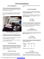
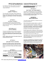
1
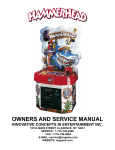
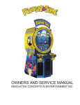
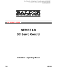
OWNERS AND SERVICE MANUAL
INNOVATIVE CONCEPTS IN ENTERTAINMENT INC.
10123 MAIN STREET, CLARENCE, NY 14031
SERVICE: 1-716-759-0360
FAX: 1-716-759-0884
E-MAIL: [email protected]
WEBSITE: www.icegame.com
PDF created with pdfFactory trial version www.pdffactory.com
TABLE OF CONTENTS
INTRODUCTION…………………………………….....PAGE 3
•
•
•
DESCRIPTION
GAME FEATURES
GAME PLAY
SET-UP / TESTING…...…..…..……...………………..PAGE 4 - 5
PROGRAMMING……………………………...………..PAGE 6 –7
•
•
OPTION MODES
DETAILED DESCRIPTIONS
MAINTENANCE………………………………………...PAGE 7– 8
QUICK TROUBLESHOOTING……………………......PAGE 9
PARTS LISTINGS…………………………...………….PAGE 10
WARRANTY INFORMATION………………..………..PAGE 11 –12
CP9001
ICEDOC LD9101
REVISION
2
PDF created with pdfFactory trial version www.pdffactory.com
06-16-03
9-23-04
INTRODUCTION
DESCRIPTION
Thank you for purchasing I.C.E. Games newest
ticket dispensing game, LINE DRIVE™.
LINE DRIVE™ is a fun and challenging game of
skill, which is simple to play and exciting for
everyone who plays it. It has a simplistic design,
using a single pushbutton to “swing” the bat at a
pitched ball.
GAME FEATURES
Vocal cues from the “announcer” help introduce the
novice to the game.
“Announcer” lets player know what bonus or reward
has been given.
Easy-to-understand playfield and game graphics.
GAME PLAY
Player drops coins into acceptor to start game.
Game “announcer” cues the player that the pitch is
coming, flashing lamps for the “Here Comes the
Pitch” sign (at the top of the playfield) and the
“Swing” button (at the bottom of the playfield).
The game ball is then delivered into play at the top
ball scoop toward the player’s bat.
Player has one chance to push the “Swing” button to
hit the ball into play.
Missing the ball will cause the “announcer to say
“Strike one (two, or three)”. Baseball rules apply.
Three strikes, you’re out, three outs, game over.
Getting a “hit” (hitting any of the targets at the top of
the playfield or hitting the ball back down the ball
scoop) will award the appropriate “base” by moving
the lit lamps on the playfield to the correct location
(s), adding tickets won to the total in the display,
clearing any accumulated strikes for that out, and
going on to the next pitch. If a run is scored, the
tickets accumulated and the “Run batted in” ticket(s)
are awarded and the game is over.
Player will continue to “bat” until he either scores a
run or strikes out three times. A “mercy” ticket award
may be given if the player does not score any runs
or hit any targets.
3
PDF created with pdfFactory trial version www.pdffactory.com
SET-UP / TESTING
SAFETY PRECAUTIONS
IMPORTANT: FAILURE TO FOLLOW THESE DIRECTIONS CLOSLY COULD CAUSE SERIOUS DAMAGE
TO YOUR GAME.
WARNING: WHEN INSTALLING THIS GAME, A 3
PRONG GROUNDED RECEPTACLE MUST BE
USED. FAILURE TO DO SO COULD RESULT IN
SERIOUS INJURY TO YOURSELF OR OTHERS.
FAILURE TO USE A GROUNDED RECPTACLE
COULD ALSO CAUSE IMPROPER GAME OPERATION, OR DAMAGE TO THE ELECTRONICS.
DO NOT DEFEAT OF REMOVE THE GROUNDING
PRONG ON THE POWER CORD FOR THE SAME
REASONS AS GIVEN ABOVE. USING AN IMPROPERLY GROUNDED GAME COULD VOID
YOUR WARRANTY.
PAY SPECIAL ATTENTION TO THE SET UP SECTION BELOW, REGARDING THE VOLTAGE SETTINGS.
GAME SET-UP
BEFORE PLUGGING THE GAME IN, OR TURNING IT
ON, BE SURE THE GAME HAS BEEN SET TO THE
PROPER VOLTAGE. YOUR GAME SHOULD COME
PRE-SET FROM THE FACTORY WITH THE CORRECT
VOLTAGE. HOWEVER IT IS A GOOD IDEA TO CHECK
THE A.C. WALL RECEPTACLE VOLTAGE BEFORE
PLUGGING THE GAME IN.
A.C. LINE VOLTAGE
ADJUSTMENT
To adjust the game for a different A.C. voltage:
1. Unplug the game from the outlet
2. Disconnect the power cord from the power module.
3. Using a small flat blade screwdriver, pry the fuse
holder from the power module.
4. Notice a small window on the fuse holder with an arrow that points to the voltage the game is presently
set alt.
5. Using the small flat blade screwdriver, lift the retaining
tab that holds the voltage selector in the fuse holder.
6. Rotate the voltage selector until the voltage you want
is displayed in the voltage select window.
7. Push the voltage selector back into the fuse holder
until it snaps into place. NOTE: Do not force the selector into the fuse holder. If it does not go in easily, it
is not being installed correctly.
8. Snap the fuse holder assembly back into the power
module.
9. Plug the power cord back into the receptacle in the
power module, and into the wall outlet.
NOTE: WHEN CHANGING FROM 110-120 TO 220-240,
LOWER THE MAIN FUSE VALUE BY ½.
WHEN CHANGING FROM 220-240 TO 110-120,
DOUBLE THE MAIN FUSE VALUE.
The Game comes with 4 available voltage settings as described below. These settings Should be used to provide
power in the correct range to the game without over or
under powering it.
POWER RANGE
90 – 110 V.A.C.
110 – 130 V.A.C.
200 – 220 V.A.C.
220 – 240 V.A.C.
VOLTAGE SETTING
110
120
220
240
The game uses a POWER MODULE to handle all of the
power distribution chores on the game. It incorporates an
ON-OFF switch, primary A.C. game fusing, and power
switching capabilities, for using the game with a wide variety of A.C. voltages by re-strapping the main transformer.
4
PDF created with pdfFactory trial version www.pdffactory.com
SET-UP / TESTING
TESTING
SET-UP
1. Locate the game to its permanent location.
Adjust the tilt bob to the desired sensitivity up/down and
center it in the bottom bracket opening.
2. Be sure the game has been properly plugged into a 3
prong grounded outlet, and that the receptacle is in good
working order.
3. If using an extension cord, be sure it is a 3 prong
grounded type of at least 16 Ga. materials.
4. Adjust the leg levers and lock into position. Open coin
door and reach up inside the front wall to unlock the game
playfield. There are two clamps, one at each top front
corner. When these locks are disengaged, carefully lift
the playfield (it is heavy) and put the support rod (hanging
on the right underside of the playfield) into the receiver
block on the inside wall of the cabinet.
Lower the playfield back into playing position. If you
choose to not relock the playfield at this time, DON’T
FORGET TO DO SO later!!
1. Verify that the game is set up for proper voltage, and
the power to the game is on.
2. Insert coins at least ten times into each coin mech to
assure proper operation. An audible sound should be
heard each time a coin is dropped.
3. Check the coin counter (located inside the coin door)
and check for proper operation.
LOCKING CLAMPS
4. Run tickets through the ticket dispenser by playing
games. Check that tickets do not get stuck behind ticket
louver.
5. Check each ticket counter for proper operation.
6. Check to see that the proper amount of tickets are dispensed based on the target hits and options selected..
SUPPORT ROD
7. Check that all door locks work smoothly.
8. Check game volume during busy time at location to set
it at the proper level.
RECEIVER
BLOCK
IF YOU HAVE ANY QUESTIONS OR COMMENTS REGARDING INSTALLATION OR
PROPER FUNCTION OF THE GAME,
PLEASE CALL OUR SERVICE DEPARTMENT
AT 1-716-759-0360
DO NOT SUPPORT THE
PLAYFIELD FROM ANYTHING ELSE!!
5
PDF created with pdfFactory trial version www.pdffactory.com
PROGRAMMING
PROGRAMMING
“TICKETS” display located on the left side of the back
glass.
This section will give you a detailed explanation of the
functions and operating characteristics of each of the programming buttons. Please read this section carefully to
avoid problems with your game.
NOTE: THE PROGRAMMING BUTTONS SHOWN BELOW, ARE LOCATED ON THE TOP OF THE CASH
BOX.
OPTION MODES
Please read the setting information carefully BEFORE
making any adjustments. Failure to set options properly
can yield unexpected results.
PLEASE NOTE: THE VALUES PRE-SET AT THE FACTORY HAVE BEEN FOUND TO WORK BEST FOR
MOST LOCATIONS.
PROGRAMMING BUTTON
OPTION BUTTON
OPTION 0
(VOLUME)
SELECT BUTTON
The number set in this mode controls the relative volume
of sound. “9” equals the minimum, “0” equals the maximum. As this button is pushed, a sound is played to
make it easier to determine where the volume should be
set. The default for this mode is “2”.
OPTION 1
(COINS PER CREDIT)
PROGRAMMING BUTTON
This button is used to enter the “Programming” mode. It
is located on the top of the cash box, inside the coin door.
Press this button once to enter the programming mode.
The number set in this mode, is the number of coins necessary (1 – 9) to earn 1 credit, and play 1 game. The default for this mode is “1”.
OPTION 2
(TICKET TABLE)
Once in this mode you can push the Option or Select Button to make adjustments to the game.
To exit the programming mode and return to game play,
push this button once again.
OPTION BUTTON
This button is used to advance through all of the various
programming option modes. Each push of this button, will
move you to the next programmable option. The option
number is displayed on the large “HOME RUN BONUS”
display in the back glass.
There are four tables to this mode. The table selected will
award the designated number of tickets for each type of
hit (suggested play price):
Table #
0 (.25 play)
1 (.50)
2 (.75)
3 (.25)
The default value in this mode is #0.
OPTION 3
(HOME RUN BONUS VALUE)
SELECT BUTTON
Each push of this button will advance you to the next
available “value” for a particular programmable option.
The value for the Select Button is shown on the smaller
Single Double Triple
2
4
6
4
6
8
6
8
10
1
2
3
The minimum setting for this mode is 25. The setting increases by a value of 25 each time the button is pressed,
6
PDF created with pdfFactory trial version www.pdffactory.com
PROGRAMMING / MAINTENANCE
to a maximum of 250. Factory default for this setting is
100. This setting value is automatically doubled for
“Grand Slam Bonus”.
OPTION 4
(MERCY TICKETS)
The value shown is the number of tickets awarded to a
player for striking out three times in one game, not scoring any runs, or getting any hits. Minimum value for this
setting is zero (0), maximum is nine (9). Factory default is
one (1).
OPTION 5
(ATTRACT AUDIO)
This enables the game to cycle a randomly selected
sound call if the game is not being played. This option is
either set “ON” (0) or “OFF” (1). Factory default for this
setting is zero (0).
OPTIONS 6 & 7
(PITCH SPEED)
The game will randomly select from these two tables to
determine what speed the “pitcher” will use. Minimum
value for these settings is five (5) and maximum is thirty
(30). Factory default values for both of these settings are
five (5).
NOTE: Setting options 6 and 7 the same will keep all
pitches at the same speed.
OPTION 8
(RUN BATTED IN AWARD)
Scoring a run will finish the game, enable the player to
collect his accumulated “hit tickets” and award a “Run
Batted In” ticket award. Minimum setting for this mode is
zero (0), and maximum is twenty (20). Default setting is
two (2).
runners batted in (runs scored) at the end of game.
Factory default for this setting is zero (0).
OPTION 10
(FACTORY OPTIONS RESET)
This option is automatically set to zero (0). Setting this
option to one (1), and immediately exiting these menus,
will reset all variables to their factory settings. Exiting
these menus with the value set to zero (0) will not affect
any of the manually selected variables.
GENERAL
MAINTENANCE
This game has been designed for an absolute minimum
amount of maintenance.
When the time comes to replace a bulb, you will notice
that 2 or 3 bulbs have burned out within a couple of
weeks time from each other. At this point, it is advisable
to change all of the bulbs. The bulbs are a very simple
push in type, very easy to change, and very inexpensive.
Changing all of the bulbs at once, will save you work in
the long run, and keep the game looking good.
Should a target need to be replaced, it can be detached
from the playfield by unscrewing the two attaching screws
and disconnecting the harness plug. Reversing the plug
when reattaching will cause the target to fail.
Replacing the “bat” coil is done by unscrewing the two coil
stop bracket screws. Remove the coil from the assembly.
If the coil overheated, the nylon sleeve inside the coil
should also be replaced.
If the “bat” on the playfield is out of alignment, loosen the
shaft clamp on the bottom of the assembly. Rotate the
bat/shaft assembly to the desired location and re-tighten.
DO NOT OVER TIGHTEN. If the clamp bottoms out to
itself, it will lose its gripping power and need to be replaced.
OPTION 9
(TICKET AWARD FOR RUNS SCORED
AT END OF GAME)
This option controls the tickets awarded for the end of
game scoring. The zero (0) setting will award the value of
OPTION 8 only at the end of game. The one (1) setting
will award the value of OPTION 8 times the number of
7
PDF created with pdfFactory trial version www.pdffactory.com
MAINTENANCE
If the “bat” needs to be replaced, loosen the screw at the
top of the bat shaft. Remove and replace bat. Use locktite when replacing the top screw!
Replacing the “pitch” coil is done by unscrewing the two
plunger stop Nylock nuts. Remove the bracket, plunger
and spring. The opto PC boards must also be removed to
access the Nylock nuts retaining the coil. Remove and
replace the coil from the assembly. If the coil overheated,
the nylon sleeve inside the coil should also be replaced.
CLEANING
Regular cleaning of the game will keep it looking new,
and greatly enhance its appeal.
Clean the cabinetry with a good cleaner such as Fantastik
or 409. A mild soapy solution can also be used.
NOTE: DO NOT USE ALCOHOL, THINNERS OF ANY KIND,
OR PINBALL PLAYFIELD CLEANERS ON ANY OF THE
CABINET SURFACES, ESPECIALLY THE DECALS.
8
PDF created with pdfFactory trial version www.pdffactory.com
QUICK TROUBLESHOOTING
PROBLEM
PROBABLE CAUSE
SOLUTION
NO GAME POWER
ON-OFF SWITCH ON GAME TURNED OFF
A.C. POWER FUSE BLOWN
GAME NOT PLUGGED IN OR CORD DAMAGED BAD
TRANSFORMER
TRANSFORMER HARNESS NOT CONNECTED
BAD POWER MODULE
TURN POWER ON
REPLACE WITH PROPER FUSE
CHECK POWER CORD
CHECK FOR PROPER VOLTAGES
CHECK HARNESS
REPLACE POWER MODULE
GAME WILL NOT TAKE MONEY
OR GIVE CREDITS CORRECTLY.
BAD COIN SWITCH
COINS PER CREDIT SETTING INCORRECT
BAD COIN MECHANISM
LOOSE OR DAMAGED HARNESSING
BAD MAIN P.C. BOARD
BAD 5 VOLT POWER SUPPLY FUSE
CHECK W/METER OR REPLACE
CHECK PROGRAMMABLE SETTING
ADJUST OR REPLACE
CHECK W/METER AND REPAIR
REPAIR OR REPLACE MAIN BOARD
CHECK AND REPLACE FUSE
TICKETS DO NOT DISPENSE OR
DISPENSE INCORRECTLY
TICKET RESET BUTTON NOT PUSHED
TICKET DISPENSER OPTICAL SENSOR DIRTY
TICKET DISPENSER HARNESSING BAD
TICKET DISPENSER BAD
BAD MAIN P.C. POWER BOARD
BAD 5 VOLT POWER SUPPLY FUSE
PRESS RESET BUTTON
CLEAN OPTICAL SENSOR
CHECKW/METER AND REPAIR
REPLACE DISPENSER
REPLACE MAIN P.C. BOARD
CHECK AND REPLACE FUSE
BASE / TARGET LIGHT BULBS DO
NOT LIGHT
BAD LIGHT BULB(S)
BAD LIGHT P.C. BOARD
BAD INTERCONNECT HARNESSING
BAD MAIN P.C. BOARD
LIGHT POWER SUPPLY FUSE BAD
BAD 5 VOLT POWER SUPPLY FUSE
REPLACE LIGHT BULB(S)
REPLACE LIGHT P.C. BOARD
CHECK W/METER AND REPAIR
REPAIR OR REPLACE P.C. BOARD
CHECK AND REPLACE FUSE
CHECK AND REPLACE FUSE
SCORE DISPLAYS DO NOT WORK
BAD 12 VOLT STATION FUSE
BAD 5 VOLT POWER SUPPLY FUSE
BAD SCORE DISPLAY P.C. BOARD
BAD MAIN P.C. BOARD
BAD SCORE DISPLAY HARNESSING
CHECK AND REPLACE FUSE
CHECK AND REPLACE FUSE
REPAIR OR REPLACE P.C. BOARD
REPAIR OR REPLACE P.C. BOARD
CHECKW/METER AND REPAIR
“GRAND SLAM BONUS” OR “HERE
COMES THE PITCH” DO NOT
LIGHT
BAD LIGHT BULB(S)
BAD LIGHT P.C. BOARD
BAD INTERCONNECT HARNESSING
BAD MAIN P.C. BOARD
LIGHT POWER SUPPLY FUSE BAD
BAD 5 VOLT POWER SUPPLY FUSE
REPLACE LIGHT BULB(S)
REPLACE LIGHT P.C. BOARD
CHECK W/METER AND REPAIR
REPAIR OR REPLACE P.C. BOARD
CHECK AND REPLACE FUSE
CHECK AND REPLACE FUSE
LOW / NO TICKET INDICATOR LED
DOES NOT WORK
BAD INDICATOR L.E.D.
L.E.D. INSTALLED BACKWARDS
STATION HARNESSING BAD
TICKET MICRO SWITCH BAD
MAIN P.C. BOARD BAD
REPLACE L.E.D.
REVERSE L.E.D.
CHECK W/METER AND REPAIR
REPLACE MICRO SWITCH
REPAIR OR REPLACE P.C. BOARD
SWING BUTTON DOES NOT OPERATE BAT
BAD BUTTON SWITCH
BAD BAT COIL
BAD HARNESSING
BAD MAIN P.C. BOARD
REPLACE SWITCH
REPLACE COIL/SLEVE
CHECK W/METER AND REPAIR
REPAIR OR REPLACE P.C. BOARD
BALL DOES NOT GET PITCHED
BAD PITCH COIL
BAD HARNESSING
BAD MAIN P.C. BOARD
GAME MISSING BALL
REPLACE COIL/SLEVE
CHECK W/METER AND REPAIR
REPAIR OR REPLACE P.C. BOARD
REPLACE BALL
9
PDF created with pdfFactory trial version www.pdffactory.com
PARTS LISTING
MECHANICAL PARTS
WA5001
FP1019S
LD3009
LD3015
LD3061
LD3062
LD3127
MZ2005
COIN DOOR
LEVELER FOOT
BAT (PLAYFIELD)
BALL (1” NYLON)
BAT (LEFT)
BAT (RIGHT)
GLASS (PLAYFIELD)
BUTTON (4” ROUND, WHITE)
ELECTRONIC PARTS
8284
8312
8395
AR2007
CG2027
BW2017
BW2018
HH5005
LD2008X
LD2009X
LD2032X
LD2034X
WS2032X
BALLAST
BULB (PL-L 40 W FLUORESCENT)
BULB (#192 WEDGE)
SPEAKER (6 X 9)
POWER CORD
BULB PLASTIC CLIP
BULB PLASTIC SUPPORT
TICKET DISPENSER
BAT SOLENOID ASSEMBLY
PITCH SOLENOID ASSEMBLY
PCBA (DISPLAY)
PCBA (MAIN)
PCBA (DISPLAY)
GRAPHICS & DECALS
LD7004
LD7008
LD7010
LD7013
LD7014
LD7015
LD7019
LD7023
LD7024
LD7025
LD7026
LD7027
LD7035
LD7036
LD9101
DECAL (BUTTON SWING)
DECAL (INSTRUCTIONS)
DECAL (PODIUM FRONT)
DECAL (PLAYFIELD SET)
DECAL (BACKWALL FENCE)
DECAL (KICK PLATE)
CROWD SCORE
DECAL (SCORE SYSTEM A)
DECAL (SCORE SYSTEM B)
DECAL (SCORE SYSTEM C)
DECAL (SCORE SYSTEM D)
MARQUEE
DECAL (BALL EJECTOR)
DECAL (HERE’S THE PITCH)
SERVICE MANUAL
10
PDF created with pdfFactory trial version www.pdffactory.com
Warranty
I.C.E warrants all components in the LINE DRIVE™ game to be free of defects in
materials and workmanship for a period of ninety days from the date of purchase.
This warranty does not cover items damaged due to normal wear and tear, subjected to abuse, improperly assembled by the end user, modified, repaired, or operated in a fashion other than that described in the service manual.
If your LINE DRIVE™ game fails to conform to the above-mentioned warranty,
I.C.E.'s sole responsibility shall be at its option to repair or replace any defective
component with a new or remanufactured component of equal to or greater O.E.M.
specification.
I.C.E. will assume no liability whatsoever, for costs associated with labor to replace
defective parts, or travel time associated therein.
I.C.E.'s obligation will be to ship free of charge, replacement parts by U.P.S.
Ground, U.S. mail, or other comparable shipping means. Any express mail or overnight shipping expense is at the cost of the purchaser.
Products will be covered under warranty only when:
·
The serial number of the game with the defective parts is given.
·
The serial number of the defective part, if applicable, is given.
·
Defective parts are returned to I.C.E., shipping pre-paid, in a timely fashion, if
requested by I.C.E.
·
A copy of the sales receipt is available as proof of purchase upon request of
I.C.E.
I.C.E. distributors are independent, privately owned and operated. In their judgment, they may sell parts or accessories other than those manufactured by I.C.E.
We cannot be responsible for the quality, suitability, or safety of any non-I.C.E.
part, or any modification, including labor, which is performed by such a distributor.
11
PDF created with pdfFactory trial version www.pdffactory.com
WARRANTY
ICE Inc warrants that all of its products will be free from defects in material and workmanship.
When placing a warranty request, please be prepared to provide the following information:
·
·
·
Serial Number of Game or Bill of Sale
Machine Type
A Detailed Description of the Equipment Fault Symptoms
ICE product, including Cromptons, Sam’s Billiards, Uniana and Bell Fruit is warranted as follows:
·
·
·
·
·
180 days on the Main PCB and Computers
90 days on all other components (i.e. DBV’s, Ticket Dispensers, etc)
30 days on repaired items
3 years on all Crane Harnessing
9 Months on Printers
ICE Inc shall not be obligated to furnish a warranty request under the following conditions:
·
·
·
Equipment has been subjected to unwarranted stress through abuse or neglect
Equipment has been damaged as a result of arbitrary repair/modification attempts
Equipment that has failed through normal wear and tear
ICE Inc will assume no liability whatsoever for costs associated with labor to replace defective parts or
travel time associated therein.
All defective warranty covered components will be replaced with new or factory refurbished components
equal to OEM specifications. ICE Inc will cover all UPS ground, or comparable shipping means, freight
costs during the warranty period. Expedited shipments are available for an additional charge.
Defective parts are returned to ICE Inc, at the customer’s expense, in a timely fashion.
ICE distributors are independent, privately owned and operated. In their judgment, they may sell parts
and/or accessories other than those manufactured by ICE Inc. We cannot be responsible for the quality,
suitability or safety of any non-ICE part, modification (including labor) that is performed by such a
distributor.
I.C.E. Parts/Service Dept.
Innovative Concepts in Entertainment
10123 Main St.
Clarence, NY 14031
Phone #: (716) - 759 – 0360
Fax #: (716) – 759 – 0884
12
PDF created with pdfFactory trial version www.pdffactory.com