1
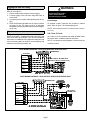
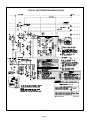
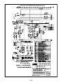
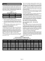
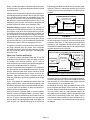
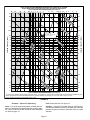
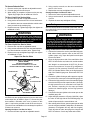
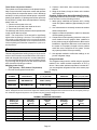
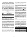
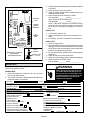
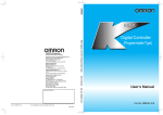
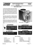
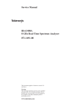
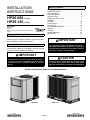
INSTALLATION INSTRUCTIONS Table of Contents HP29-090 (7.5 TON) HP29-120 (10 TON) HEAT PUMPS 504,342M 11/2000 See unit nameplate for manufacturer and address. 2000 Litho U.S.A. Shipping & Packing List Shipping & Packing List . . . . . . . . . . . . . . . . . . . . . . . 1 General Information . . . . . . . . . . . . . . . . . . . . . . . . . . 1 Unit Dimensions . . . . . . . . . . . . . . . . . . . . . . . . . . . . . 2 Parts Arrangement . . . . . . . . . . . . . . . . . . . . . . . . . . . 3 Setting the Unit . . . . . . . . . . . . . . . . . . . . . . . . . . . . . . 6 Rigging the Unit for Lifting . . . . . . . . . . . . . . . . . . . . . 7 Electrical . . . . . . . . . . . . . . . . . . . . . . . . . . . . . . . . . . . . 7 Plumbing . . . . . . . . . . . . . . . . . . . . . . . . . . . . . . . . . . . 10 Service Valves . . . . . . . . . . . . . . . . . . . . . . . . . . . . . . 15 Leak Testing . . . . . . . . . . . . . . . . . . . . . . . . . . . . . . . . 16 Evacuation & Dehydration . . . . . . . . . . . . . . . . . . . . 17 Start-Up . . . . . . . . . . . . . . . . . . . . . . . . . . . . . . . . . . . . 17 Charging . . . . . . . . . . . . . . . . . . . . . . . . . . . . . . . . . . . 18 System Operation . . . . . . . . . . . . . . . . . . . . . . . . . . . 19 Maintenance . . . . . . . . . . . . . . . . . . . . . . . . . . . . . . . . 21 1 - Assembled heat pump unit Check the unit for shipping damage. If you find any damĆ age, immediately contact the last carrier. General Information These instructions are intended as a general guide and do not supersede national or local codes in any way. Consult authorities having jurisdiction installation. IMPORTANT The Clean Air Act of 1990 bans the intentional ventĆ ing of refrigerant (CFC's and HCFC's) as of July 1, 1992. Approved methods of recovery, recycling or reclaiming must be followed. Fines and/or incarceraĆ tion may be levied for noncompliance. IMPORTANT Improper installation, adjustment, alteration, service or maintenance can cause property damage, personĆ al injury or loss of life. Installation and service must be performed by a qualified installer or service agency. CAUTION As with any mechanical equipment, personal injury can result from contact with sharp sheet metal edges. Be careful when you handle this equipment. RETAIN THESE INSTRUCTIONS FOR FUTURE REFERENCE HP29-120 HP29-090 11/00 *2P1100* 504,342M Page 1 *P504342M* HP29-090 Series Dimensions - inches (mm) CORNER WEIGHT AA Model No No. lbs. 121 HP29-090 BB kg 55 lbs. 146 CENTER OF GRAVITY CC kg 66 DD lbs. 130 kg 59 lbs. 109 EE Model No No. kg 49 inch 22-1/2 HP29-090 FF mm 572 inch 19 OUTDOOR FAN AND GUARD AA EE INLET AIR BB COMPRESSOR OUTDOOR COIL INLET AIR FF CENTER OF GRAVITY OUTDOOR COIL DD 15Ć1/2 (394) CC INLET AIR TOP VIEW OPTIONAL HAIL GUARD (Field Installed All Coil Sides) 48 (1219) OPTIONAL HAIL GUARD (Field Installed All Coil Sides) 34 (864) OPTIONAL 115 VOLT OUTLET (Factory Installed Inside Unit) DISCHARGE AIR CONTROL BOX CONTROL BOX ACCESS ELECTRICAL INLETS (Either Side) 43-1/4 (1099) 1-1/4 (32) 2Ć1/4 (57) VAPOR LINE (Either Side) 6Ć1/2 (165) 49Ć3/4 (1264) LIFTING HOLES (For Rigging) FORKLIFT SLOTS (Both Sides) BASE OPTIONAL DISCONNECT (Factory Installed) COMPRESSOR 46-1/2 (1181) 11-1/2 (292) LIQUID LINE (Either Side) SIDE VIEW Page 2 3Ć1/4 (83) 35Ć3/4 (908) BASE SERVICE VIEW mm 483 HP29-120 Series Dimensions - inches (mm) CORNER WEIGHT Model No No. HP29-120 AA BB CENTER OF GRAVITY CC DD lbs. kg lbs. kg lbs. kg lbs. kg 130 59 183 83 183 83 130 59 Model No No. HP29-120 EE FF inch mm inch mm 25 635 17-3/4 451 EE AA BB OUTDOOR COIL FF CONTROL BOX OUTDOOR COIL DD INLET AIR OUTDOOR FANS AND GUARDS (2) TOP VIEW CENTER OF GRAVITY CC OPTIONAL HAIL GUARD (Field Installed Both Sides) OPTIONAL HAIL GUARD (Field Installed Both Sides) OPTIONAL 115 VOLT OUTLET (Factory Installed Inside Unit) 58Ć5/8 (1489) OPTIONAL DISCONNECT (Factory Installed) DISCHARGE AIR CONTROL BOX ELECTRICAL INLETS (Either Side) SUCTION LINE (Either Side) 3-1/2 (89) 2Ć1/8 (54) 60Ć3/8 (1534) LIFTING HOLES (For Rigging) SIDE VIEW 15Ć1/2 (394) 34 (864) BASE FORKLIFT SLOTS (Both Sides) CONTROL BOX ACCESS COMPRESSOR 49 (1245) 4Ć3/4 (121) 6Ć1/2 (165) LIQUID LINE (Either Side) 3Ć1/4 (83) 35Ć3/4 (908) BASE SERVICE VIEW Page 3 HP29-090 Unit Parts Arrangement CONTROL BOX FAN GUARD OUTDOOR FAN (B4) REVERSING VALVE DEFROST THERMOSTAT (S6) COMPRESSOR (B1) DEFROST PRESSURE SWITCH (S46) HIGH PRESSURE SWITCH (S4) VAPOR LINE SERVICE VALVE LOW AMBIENT SWITCH (S11) LOSS OF CHARGE SWITCH (S24) LIQUID LINE SERVICE VALVE FIGURE 1 HP29-120 Unit Parts Arrangement OUTDOOR FANS (B4, B5) FAN GUARD CONTROL BOX REVERSING VALVE DEFROST THERMOSTAT (S6) COMPRESSOR (B1) LOW AMBIENT SWITCH (S11) HIGH PRESSURE SWITCH (S4) LOSS OF CHARGE SWITCH (S24) DEFROST PRESSURE SWITCH (S46) LIQUID LINE SERVICE VALVE VAPOR LINE SERVICE VALVE FIGURE 2 Page 4 HP29-090 Control Box Arrangement TRANSFER RELAY K8 COMPRESSOR CONTACTOR K1 DISCONNECT SWITCH S48 LOW AMBIENT BY-PASS RELAY K58 OUTDOOR FAN RELAY K10 DEFROST RELAY K4 CMCI DEFROST/TIMER GROUND LUG RELAY SWITCH K6 CAPACITOR C1 TERMINAL STRIP TB14 FIGURE 3 HP29-120 Control Box Arrangement RELAY SWITCH K6 TERMINAL STRIP TB14 CMCI DEFROST/TIMER DISCONNECT SWITCH S48 COMPRESSOR CONTACTOR K1 OUTDOOR FAN RELAY K10 TRANSFER RELAY K8 OUTDOOR FAN RELAY K68 LOW AMBIENT BY-PASS RELAY K58 GROUND LUG DEFROST RELAY K4 CAPACITORS C1, C2 LOW AMBIENT THERMOSTAT S41 FIGURE 4 Page 5 INSTALLATION CLEARANCES WARNING NOTE - 48 IN. (1219 mm) clearance required on top of unit. Product contains fiberglass wool. HP29-090 Disturbing the insulation in this product during installation, maintenance, or repair will expose you to fiberglass wool dust. Breathing this may cause lung cancer. (Fiberglass wool is known to the State of California to cause cancer.) OUTDOOR COIL 36 (914))* Fiberglass wool may also cause respiratory, skin, and eye irritation. To reduce exposure to this substance or for further information, consult material safety data sheets available from address shown below, or contact your supervisor. Lennox Industries Inc. 36 (914)* 36 (914) OUTDOOR COIL 36 (914)* P.O. Box 799900 Dallas, TX 75379-9900 HP29-120 Setting the Unit Refer to unit dimensions on page 1 for sizing mounting slab, platforms or supports. Refer to figure 5 for installation clearances. 36 (914)* OUTDOOR COIL Slab Mounting When installing unit at grade level, install on a level slab high enough above grade to allow adequate drainage of water. Top of slab should be located so run-off water from higher ground will not collect around unit. 36 (914)** 36 (914) OUTDOOR COIL Roof Mounting 36 (914)* Install unit at a minimum of 4 inches above surface of the roof. Care must be taken to ensure weight of unit is properly distributed over roof joists and rafters. Either redwood or steel supports are recommended. *One of the these clearance distances may be reduced to 18" (457 mm). **This clearance may be reduced to 12" (305 mm). FIGURE 5 RIGGING INSTRUCTIONS *WEIGHT LBS. KG. UNIT HP29-090 HP29-120 506 626 230 284 *Maximum weight with all available factory-installed accessories. LIFTING POINT SHOULD BE DIRECTLY ABOVE CENTER OF GRAVITY CAUTION - Do not walk on unit. IMPORTANT - ALL PANELS MUST BE IN PLACE FOR RIGGING. FIGURE 6 Page 6 Rigging the Unit for Lifting Rig unit for lifting by attaching four cables to holes in unit base rail. See figure 6. 1 - Detach wooden base protection before rigging. 2 - Connect rigging to the unit base using both holes in each corner. 3 - All panels must be in place (with spreader bars) for rigĆ ging. 4 - Place fieldĆprovided spreader bars in place just above top edge of unit. The frame must be of adequate strength and length. (Spreader bars prevent damage to top of unit.) Electrical Wiring must conform to current standards of the National Electric Code (NEC), Canadian Electrical Code (CEC) and local codes. Refer to the blower coil or furnace installation instructions for additional wiring application diagrams and refer to unit rating plate for minimum circuit ampacity and maximum overcurrent protection size. WARNING Unit must be grounded in accordance with national and local codes. Electric Shock Hazard. Can cause injury or death. Line Voltage To facilitate conduit, knockouts are provided in cabinet panel. Refer to figure 7 for field wiring diagram. NOTE - Units are approved for use with copper conducĆ tors only. 24V, Class II Circuit 24V, Class II circuit connections are made up below control box. Route wire in conduit to bottom of control box. NOTE - A complete unit wiring diagram is located inside the control box panel. FIELD WIRING DIAGRAM -- HP29 WITH AUXILIARY ELECTRIC HEAT THERMOSTAT HP29 UNIT YELLOW CB17/CBH17 BLOWER COIL (With EH17 Electric Heat Section) GREEN GREEN RED GRAY FIELD WIRING DIAGRAM -- HP29 WITHOUT AUXILIARY ELECTRIC HEAT HP29 UNIT THERMOSTAT YELLOW CB17/CBH17 BLOWER COIL GREEN RED GRAY GREEN FIGURE 7 Page 7 TYPICAL UNIT WIRING DIAGRAM HP29-090 *2P1100* *P533542W* FIGURE 8 Page 8 TYPICAL UNIT WIRING DIAGRAM HP29-120 *2P1100* *P533543W* FIGURE 9 Page 9 Plumbing Field refrigerant piping consists of liquid and vapor lines from the heat pump unit. Piping may be brought into the unit through either side. Remove the knockouts on the mullions and install the provided rubber grommets into the piping holes. Remove the plugs from the liquid and vapor lines. Refer to table 1 for fieldĆfabricated refrigerant line sizes for runs up to 50 linear feet (15 m). TABLE 1 REFRIGERANT LINE SIZES UNIT LIQUID LINE VAPOR LINE HP29-090 5/8 in. (16 mm) 1-3/8 in. (35 mm) HP29-120 5/8 in. (16 mm) 1-3/8 in. (35 mm) Refrigerant Line Brazing Procedure 1 - End of refrigerant line must be cut square, kept round, free from nicks or dents and deburred (I.D. and O.D.) 2 - Wrap a wet cloth around the valve body when brazing to prevent possible heat damage to the valve core and port. 3 - Install filter drier, provided with unit, in the liquid line as close as possible to the expansion device. Refrigerant Line Limitations Unit applications with line set lengths up to 50 linear feet (15 m) (excluding equivalent length of fittings) may be installed using refrigerant line sizes as outlined in table 1. Refrigerant lines from 50 to 100 linear feet (15 to 30 m) should be sized in accordance with the following secĆ tion. The maximum line length is 100 feet (30 m). Maximum suction rise must not exceed 45 linear feet (13.7 m) and maximum liquid head must not exceed 45 linear feet (13.7 m). Refer to the refrigerant piping guideline manual (Corp. 9351-L9) if line lengths exceed 50 feet (15 m). In these applications, you must install a liquid line solenoid valve at the evaporator coil. In addition, use expansion valves only (RFC and capĆtube expansion devices are not acĆ ceptable). In applications where the lines exceed 75 feet (23 m), install the solenoid valve with a nonĆrecycling pumpĆdown control. NOTE - When refrigerant line solenoid valves are installed, velocities should not exceed 300 fpm (1.5 m/s) in order to avoid liquid line hammer. All units are equipped with a low ambient (head pressure) control to allow for cooling down to 0°F (-18°C). Due to the additional refrigerant required to fill the lines, the likelihood of slugging is greatly increased with lines that are over 50 feet (15 m) in length. An incremental inĆ crease in liquid line size results in a 40 to 50 percent inĆ crease in liquid to fill the line. Therefore, it is desirable to use the smallest liquid line size possible. Pipe Sizing, Line Layout and Design [Line set lengths from 50 - 100 linear feet (15 - 30 m)] Start by making a sketch of the system showing relative locations of the heat pump unit and the indoor coil, length of each piping segment, elbows, tees, valves, etc. This inforĆ mation will be used to determine the equivalent length of the piping run. Also, take note of any difference in elevation between the outdoor and indoor units. Vapor and liquid lift must be considered to ensure proper pipe sizing. Liquid Line Function and Design The liquid line must convey a full column of liquid from the outdoor unit to the metering device at the indoor coil withĆ out flashing. In order to ensure this, liquid line pressure drop and pressure across the expansion device and disĆ tributor must be considered. TABLE 2 HCFCĆ22 SATURATION TEMPERATURES (Condensing Temperatures at Different Pressures) HCFCĆ22 Pressure Temperature Table (Psig) Degrees F (°C) HCFC22 Degrees F (°C) HCFC22 Degrees F (°C) HCFC22 Degrees F (°C) HCFC22 Degrees F (°C) HCFC22 -40 (-41) -30 (-34) 0.6 4.9 18 (-8) 20 (-7) 41.1 43.3 36 (2) 38 (3) 63.3 66.1 75 (24) 80 (27) 133.4 145.0 120 (49) 125 (52) 262.5 280.7 -20 (-28) 10.2 22 (-6) 45.5 40 (4) 69.0 85 (29) 157.2 130 (54) 299.7 -10 (-23) 16.6 24 (-4) 47.9 45 (7) 76.6 90 (32) 170.0 135 (57) 319.6 0 (-18) 24.1 26 (-3) 50.3 50 (10) 84.7 95 (35) 183.6 140 (60) 340.3 10 (-12) 32.9 28 (-2) 52.7 55 (13) 93.3 100 (38) 197.9 145 (63) 362.0 12 (-11) 34.9 30 (-1) 55.2 60 (16) 102.4 105 (41) 212.9 150 (66) 384.6 14 (-10) 36.9 32 (0) 57.8 65 (18) 112.2 110 (43) 228.6 155 (68) 406.3 16 (-9) 39.0 34 (1) 60.5 70 (21) 122.5 115 (46) 245.2 160 (71) 433.3 Page 10 HCFCĆ22 LIQUID LINE PRESSURE DROP/VELOCITY At 45°F Evaporating Temperature and 125°F Condensing Temperature 30 20 15 .5 .4 .3 .2 30 25 25 20 20 15 15 12.5 EXAMPLE: 10 TON UNIT 5/8 IN. O.D. LINE 4.25 PSI DROP PER 100 FEET 275 FPM VELOCITY 10 COOLING CAPACITY (TONS) HCFCĆ22 LIQUID LINE PRESSURE DROP (lbs./100 Feet) 10 9 8 7 6 5 4 3 2 1.5 1.0 .9 .8 .7 .6 9 10 9 8 8 7 7 6 6 5 5 4 4 3 3 2 2 COOLING CAPACITY (TONS) 40 30 1.5 1.5 1.0 1.0 .9 .9 .8 .8 .7 40 .7 10 9 8 7 6 5 4 3 2 1.5 1.0 .9 .8 .7 .6 .5 .4 .3 .2 HCFCĆ22 LIQUID LINE PRESSURE DROP (lbs./100 Feet) To use this chart, first find capacity (tons) on left side of chart. To find pipe size, proceed right to smallest pipe size. Pressure drop (vertical line) and velocity (diagonal lines) can then be determined for the pipe size selected. For example, for 10 ton unit, select 5/8 in. O.D. line. NOTE - Shaded area denotes unacceptable velocity range. 30 20 15 FIGURE 10 Page 11 TABLE 3 Example -- Liquid Line Pipe Sizing Equivalent Length in Feet of Straight Pipe for Valves and Fittings Given: 10Ćton heat pump unit on ground level with a 10Ćton indoor coil on the third level above ground and a total of 96 linear feet of piping. Unit is charged with 10°F subcooling at 125°F condensing temperature (280 psi HCFCĆ22 liquid). Refer to figure 11. Line Size O.D. in. Globe Valve Angle Valve 90° Long* Radius Elbow 45° Long* Radius Elbow Tee Line Tee Branch 3/8 1/2 7 9 4 5 0.8 0.9 0.3 0.4 0.5 0.6 1.5 2.0 5/8 12 6 1.0 0.5 0.8 2.5 3/4 14 7 1.3 0.6 0.9 3.0 7/8 15 8 1.5 0.7 1.0 3.5 1Ć1/8 22 12 1.8 0.9 1.5 4.5 1Ć3/8 28 15 2.4 1.2 1.8 6.0 1Ć5/8 35 17 2.8 1.4 2.0 7.0 2Ć1/8 45 22 3.9 1.8 3.0 10 Find: Select tube size from figure 10. LIQUID LINE SIZING EXAMPLE 53 FT. 10 TON INDOOR COIL FILTER/DRIER 2Ć5/8 51 26 4.6 2.2 3.5 12 Long radius elbow. Multiply factor by 1.5 for short radius elbow equivaĆ lent length. 3 FT. Lennox equipment above five tons in capacity typically opĆ erates at a saturated condensing temperature of 125°F (280psi per table 2). Lennox equipment is designed to hold a charge allowing 10°F subcooling at 95°F ambient. The condensing temperature and the subcooling are used to calculate the maximum allowable pressure drop as deĆ tailed below. NOTE - 95°F ambient is an arbitrary temperature chosen to represent typical summer operating conditions used to calĆ culate maximum allowable pressure drop. This temperaĆ ture (and the corresponding subcooling) may vary with reĆ gional climate. Example -- Calculating maximum allowable pressure drop: Find the maximum allowable liquid line pressure drop of a unit operating at 10°F subcooling and 125°F (280 psi) condensing temperature. Subtract 10°F subcooling temperature from 125°F condensing temperature to equal 115°F subcooled liquid temperature (245 psi / point at which flash gas will begin to form). Subtract 245 psi subĆ cooled pressure from 280 psi condensing pressure to find a maximum allowable pressure drop of 35 psi. To calculate actual pressure drop in the liquid line, calcuĆ late pressure drop due to friction and pressure drop due to vertical lift and add the two. Pressure drop due to friction in the pipe or other devices must all be considered. Pressure drop ratings for different pipe sizes are given in figure 10. Pressure drop ratings of fieldĆinstalled devices are typically supplied by the manufacturer. Pressure drop due to vertical lift (1/2 pound per foot) is typĆ ically high and can be a limiting factor in the design of the system. The liquid refrigerant pressure must be sufficient to produce the required flow through the expansion device. Liquid reĆ frigerant (free of flash gas) should be delivered to the expanĆ sion valve at a minimum of 175psi to ensure the 100 psi necĆ essary to produce full refrigerant flow at the rated capacity. 10 TON HEAT PUMP UNIT GIVEN: 10 TON EVAPORATOR 10 TON HEAT PUMP UNIT WITH 10°F SUBCOOLING at 125°F 40 FT. LENGTH OF LINE -- 96 FT. FIND: LIQUID LINE SIZE SOLUTION: PRESSURE DROP CANNOT EXCEED 35 psi. SELECT A PROPOSED TUBING SIZE: 5/8in. COPPER TWO 90° LONG RADIUS ELBOWS @ 5/8in. O.D. = 1 ft. EQUIV. FT. EA. TOTAL EQUIVALENT LENGTH = LINEAR LENGTH + EQUIVALENT LENGTH OF FITTINGS TOTAL EQUIVALENT LENGTH = 98 ft. TOTAL FRICTION LOSSES = 4.25 psi x 98 ft. = 4.17psi 100 ft. TOTAL PRESSURE DROP= TOTAL FRICTION LOSSES + LIFT LOSSES + FILTER/DRIER FILTER DROP = 1 psi (by manufacturer) LIFT LOSSES = 40 ft. x 1/2psi per foot = 20psi TOTAL PRESSURE DROP = 20 psi + 4.17 psi + 1 psi = 25.17 psi ANSWER; 5/8 IN. O.D. COPPER TUBING CAN BE USED. PRESSURE LOSS DOES NOT EXCEED MAXIMUM ALLOWABLE PRESSURE DROP (6°F TO 7°F SUBCOOLING WILL BE AVAILABLE AT THE EXPANSION VALVE) AND VELOCITY IS ACCEPTABLE. FIGURE 11 Figure 10 illustrates the relationship between liquid line sizĆ ing, pressure drop per 100 feet, velocity range and tonĆ nage. Enter figure 10 from the left and extend to the right to the smallest tube size that will not exceed 300 fpm velocity. Solution: For a 10Ćton system, 5/8 inch O.D. line with 4.25 psi per 100 feet drop (per figure 10) is selected. Now, calcuĆ late pressure drop due to friction and liquid lift to determine if this is a good selection. The total friction drop for the application will include 96 feet of 5/8 inch O.D. pipe plus 1 equivalent foot per elbow (two elbows) to equal 98 equivalent feet. In a 10Ćton system, expect 4.25 psi drop per 100 feet of 5/8 inch O.D. copper (per figure 10). Multiply 4.25/100 by 98 equivalent feet to calculate the total friction loss of 4.17 psi. Add the pressure drop caused by vertical lift. When HCFCĆ22 refrigerant is used, there is 1/2 psi pressure drop per foot of vertical lift. In this application, which has a 40Ćfoot (12 m) vertical lift, add a 20 psi pressure drop because of the lift. Page 12 Finally, consider the impact of the filter drier to the liquid, line which has a 1 psi pressure drop (this number provided by manufacturer). Add the three components of pressure drop together to find that the total pressure drop in this 5/8 inch line equals 25.17 psi which is well within our acceptable range. The 5/8 inch line, therefore, is a good selection because it is well below the maximum allowable pressure drop, is in a satisfactory velocity range, uses minimum refrigerant and provides sufficient pressure at the expansion valve. Alternative Sizing: Suppose 3/4 inch O.D. line with 1.6 psi drop per 100 feet had been selected. The total equivaĆ lent length is equal to the linear length (96 feet) plus the equivalent length of the fittings (from table 3, two 90° ells at 1.25 feet each). The total equivalent length is 98.5 feet. The total friction drop would have been 1.6/100 multiplied by 98.5 = 1.57 psi. When the pressure drop due to lift (20 psi) and the filter drier (1 psi) are added we find that the total pressure drop for 3/4 inch line equals 22.57 psi. Though the 3/4 inch line provides a lower pressure drop, the larger diameter pipe will require more refrigerant which will increase the risk of refrigerant slugging. In addiĆ tion, the smaller line will be less costly. The smaller line should be used. Engineering Handbook include the loss for a 25 feet refrigĆ erant line. Therefore, subtract the pressure loss of 25 feet of piping from the total calculated for your particular apĆ plication. DETERMINING VAPOR LINE CAPACITY LOSS IF PRESSURE DROP IS KNOWN Total Pressure Drop For Equivalent Length 25 ft. Line OUTDOOR UNIT Total Pressure Drop Minus Press. Drop in 25 ft. of Line Once Pressure Drop Is Found: Btuh lost = 1% x (Total Press. Drop minus 25 ft.) x rated capacity FIGURE 12 When an indoor coil is located above or on the same level as the heat pump, the vapor line must rise to the top of the evaporator. See figure 13. This helps prevent liquid from migrating to the compressor during the off cycle. Traps should also be installed at the bottom of all vertical risers for migration protection in the off cycle. VAPOR LINE PIPING Indoor Coil Above or On Same Level with Outdoor Unit VAPOR LINE Vapor Line Function and Design The vapor line returns refrigerant vapor and oil from the evaporator to the compressor. Vapor line design is critical. The design must minimize pressure loss in order to achieve maximum unit efficiency and provide adequate oil return to the compressor under all conditions. Because oil separates from refrigerant in the evaporator, the vapor velocity must be adequate to sweep the oil along the pipe. Horizontal vapor lines require a minimum of 800 fpm velocity for oil entrainment. In order to ensure oil enĆ trainment, vapor line risers require a minimum velocity of 1200 fpm (1500 fpm is preferred) regardless of the length of the riser. Figure 14 illustrates the relationship between vapor line sizing, pressure drop, velocity and cooling capacity. Use this chart to determine vapor line pressure drop and velocĆ ity. As the pipe size increases, so does the capacity reĆ quired to ensure oil entrainment. Vertical lift has no significant effect on system capacity. However, systems lose approximately 1 percent of capacĆ ity for every pound of pressure drop due to friction in the vaĆ por line. In order to calculate capacity loss, first estimate pressure drop in the total equivalent length of the piping run (refer to figure 14). Capacity ratings given in the Lennox INDOOR UNIT OUTDOOR UNIT RAISE PIPE TO TOP LEVEL OF COIL INDOOR COIL TRAP INDOOR COIL OUTDOOR UNIT VAPOR LINE INSTALL TRAPS AT BOTTOM OF EACH RISER If equipment is on same level, inverted trap should still be used in order to prevent liquid migration to compressor during off cycle. FIGURE 13 Horizontal vapor lines should be level or slightly sloped toĆ ward the heat pump unit. Pipe must avoid dips or low spots that can collect oil. For this reason, hard copper should be used, especially on long horizontal runs. As with liquid line sizing, begin by making a sketch of the layout complete with fittings, driers, valves etc. Measure the linear length of each line and determine the number of ells, tees, valves, driers etc. Add equivalent length of fitĆ tings (table 3) to linear length of pipe to get total equivalent length used in determining friction loss. Again, refer to manufacturer's data for pressure drop information on acĆ cessory components. The resultant pressure drop must be considered. Page 13 HCFCĆ22 VAPOR LINE PRESSURE DROP/VELOCITY PER 100 FT. OF LINE At 45°F Evaporating Temperature and 125°F Condensing Temperature 40 30 20 15 HCFCĆ22 VAPOR LINE PRESSURE DROP (lbs./100 Feet) 10 9 8 7 6 5 4 3 2 1.5 1.0 .9 .8 .7 .6 .5 .4 .2 30 25 25 20 20 15 15 12.5 EXAMPLE: 10 TON UNIT 1Ć3/8 IN. O.D. LINE 3.3 PSI DROP PER 100 FEET 2400 FPM VELOCITY 10 10 9 9 8 8 7 7 6 6 5 5 4 4 3 3 2 2 1.5 1.5 1.0 1.0 .9 .9 .8 .8 .7 COOLING CAPACITY (TONS) 12.5 COOLING CAPACITY (TONS) .3 30 .7 10 9 8 7 6 5 4 3 2 1.5 1.0 .9 .8 .7 .6 .5 .4 .3 .2 HCFCĆ22 VAPOR LINE PRESSURE DROP (lbs./100 Feet) To use this chart, first find capacity (tons) on left side of chart. To find pipe size, proceed right to smallest pipe size. Pressure drop (vertical line) and velocity (diagonal lines) can then be determined for the pipe size selected. For example, for 10 ton unit, select 1Ć3/8 in. O.D. line. NOTE - Shaded area denotes unacceptable velocity range. 40 30 20 15 FIGURE 14 Example -- Vapor Line Pipe Sizing Find: Select tube size from figure 14. Given: 7Ć1/2 ton heat pump with indoor coil lower than outĆ door coil. Application includes 82 linear feet of piping and 4 ells. There is a 20Ćfoot vertical lift and 62 feet of horizontal run. Refer to figure 15. Solution: 1Ć1/8 inch O.D. line with 6 psi per 100 feet presĆ sure drop and 2900 fpm velocity is selected. Now, calculate pressure drop due to friction to determine if this is a good selection. Page 14 The conditions in this example will allow either 1Ć1/8 inch or 1Ć3/8 inch vapor line to be used, since capacity loss is miniĆ mized and velocity is sufficient to return oil to the compresĆ sor. EXAMPLE Ć Indoor Coil Below Outdoor Unit VAPOR LINE 60 FT. Service Valves SUCTION RISER 20 FT. The liquid line and vapor line service valves and gauge ports are accessible inside of the unit. These gauge ports are used for leak testing, evacuating, charging and checkĆ ing charge. INDOOR COIL OIL TRAP 2 FT. FIGURE 15 From table 3, four ells at 1.8 equivalent feet each equals 7.2 equivalent feet. When added to the 82 feet of pipe, the total equivalent feet becomes 89.2 feet (round up to 90 feet). Multiply 6/100 by 90 equivalent feet to calculate total friction loss of 5.4 psi. Use figure 14 to calculate the pressure drop in 25 feet of 1Ć1/8 inch line. Multiply 6/100 by 25 feet to calculate friction loss of 1.5 psi. This loss has already been included in the capacity given in Lennox' Engineering Handbook, so it should be subĆ tracted from the total. IMPORTANT - Service valves are closed to line set conĆ nections. Do not open until refrigerant lines and indoor coil have been leak tested and evacuated. All precautions should be exercised to keep the system free from dirt, moisture and air. Liquid Line Service Valve All HP29 units use liquid line service valves as shown in figĆ ure 16. A Schrader valve is factory installed. A service port is supplied to protect the Schrader valve from contaminaĆ tion and serve as the primary leak seal. The capacity lost in the total equivalent length" of the reĆ frigerant line (using figures 12 and 14) equals 1 percent x (5.4 - 1.5) x 90,000. Btuh lost= 0.01 x (3.9) x 90,000 = 3510 Capacity loss for the line selected is approximately 3.9 percent. LIQUID LINE SERVICE VALVE (VALVE OPEN) INSERT HEX WRENCH HERE INLET (TO INDOOR COIL) The preceding calculation shows that this is a workable system, but it will result in losses in both capacity and effiĆ ciency. SCHRADER VALVE Alternative Sizing: Using the same (7Ć1/2 ton) example, this time select 1Ć3/8 inch O.D. line. 1Ć3/8 inch O.D. line with 2 psi per 100 feet pressure drop has 1760 fpm velocity. Now calculate pressure drop due to friction loss to determine if this is a better selection. OUTLET (TO COMPRESSOR) SERVICE PORT CAP SERVICE PORT LIQUID LINE SERVICE VALVE (VALVE CLOSED) From figure 3, four ells at 2.4 equivalent feet each equals 9.6 equivalent feet. When added to the 82 feet of pipe, the total equivalent feet becomes 91.6 feet (round up to 92 feet). INLET (TO INDOOR COIL) Multiply 2/100 by 92 equivalent feet to calculate total friction loss of 1.8 psi. Use figure 14 to calculate the pressure drop in 25 feet of 1Ć3/8 inch line. Multiply 2/100 by 25 feet to calculate friction loss of 0.5 psi. This loss has already been included in the capacity given in Lennox' Engineering Handbook, so it should be subtracted from the total. The capacity lost in the total equivalent length" of the reĆ frigerant line (using figures 12 and 14) equals 1 percent x (1.8 - 0.5) x 90,000. Btuh lost= 0.01 x (1.3) x 90,000 = 1170 Capacity loss for the line selected is approximately 1.3 percent. STEM CAP RETAINING RING INSERT HEX WRENCH HERE SERVICE PORT (VALVE FRONT SEATED) SERVICE PORT CAP SCHRADER VALVE OPEN TO LINE SET WHEN VALVE IS CLOSED (FRONT SEATED) Page 15 STEM CAP FIGURE 16 OUTLET (TO COMPRESSOR) To Access Schrader Port: 1 - Remove service port cap with an adjustable wrench. 2 - Connect gauge to the service port. 3 - When testing is completed, replace service port cap. Tighten finger tight, then an additional 1/6 turn. To Open Liquid Line Service Valve: 1 - Remove stem cap with an adjustable wrench. 2 - Using service wrench and 5/16 inch hex head extenĆ sion back the stem out counterclockwise until the valve stem just touches the retaining ring. 3 - Replace stem cap. Tighten finger tight, then tighten an additional 1/6 turn. WARNING Do not attempt to backseat this valve. Attempts to backseat this valve will cause snap ring to explode from valve body under pressure of refrigerant. PerĆ sonal injury and unit damage will result. To Close Liquid Line Service Valve: 1 - Remove stem cap with an adjustable wrench. 2 - Using service wrench and 5/16 inch hex head extension, turn stem clockwise to seat the valve. Tighten firmly. 3 - Replace stem cap and tighten finger tight, then tighten an additional 1/6 turn. Vapor Line Service Valve VAPOR LINE (BALL TYPE) SERVICE VALVE (VALVE OPEN) USE ADJUSTABLE WRENCH ROTATE STEM CLOCKWISE 90° TO CLOSE ROTATE STEM COUNTERCLOCKWISE 90° TO OPEN TO INDOOR COIL STEM CAP STEM BALL (SHOWN OPEN) TO OUTDOOR COIL SERVICE PORT CAP SERVICE PORT SCHRADER VALVE FIGURE 17 All HP29 units are equipped with a full-service ball valve on the vapor line, as shown in figure 17. One service port that contains a Schrader valve core is present in this valve. A cap is also provided to seal off the service port. The valve is not rebuildable so it must always be replaced if failure has occurred. Opening the Vapor Line Service Valve 1 - Remove the stem cap with an adjustable wrench. 2 - Using a service wrench, turn the stem counterclockĆ wise for 1/4 of a turn. 3 - Replace the stem cap and tighten it firmly. Closing the Vapor Line Service Valve 1 - Remove the stem cap with an adjustable wrench. 2 - Using a service wrench, turn the stem clockwise for 1/4 of a turn. 3 - Replace the stem cap and tighten it firmly. Leak Testing After the line set has been connected to the indoor and outĆ door units, the line set connections and indoor unit must be checked for leaks. WARNING Never use oxygen to pressurize refrigeration or air conditioning system. Oxygen will explode on conĆ tact with oil and could cause personal injury. When using high pressure gas such as nitrogen or CO2 for this purpose, be sure to use a regulator that can conĆ trol the pressure down to 1 or 2 psig (6.9 to 13.8 kPa). Using an Electronic Leak Detector or Halide 1 - Connect the hoses to the service ports With both manĆ ifold valves closed, open the valve on the HCFCĆ22 cylinder (vapor only). Open the liquid line and vapor line service valves. 2 - Open the high pressure side of the manifold to allow HCFCĆ22 into the line set, indoor unit, and the outdoor unit. Weigh in a trace amount of HCFCĆ22. [A trace amount is a maximum of 2 ounces (57g) refrigerant or 3 pounds (31 kPa) pressure]. Close the valve on the HCFCĆ22 cylinder and the valve on the high pressure side of the manifold gauge set. Disconnect HCFCĆ22 cylinder. 3 - Connect a cylinder of nitrogen with a pressure regulatĆ ing valve to the center port of the manifold gauge set. 4 - Connect the high pressure hose of the manifold gauge set to the service port of the vapor line valve. (Normally, the high pressure hose is connected to the liquid line port, however, connecting it to the vapor port better protects the manifold gauge set from high pressure damage.) 5 - Connect the nitrogen cylinder to the center port on the manifold gauge set. 6 - Adjust nitrogen pressure to 150 psig (1034 kPa). Open the valve on the high side of the manifold gauge set which will pressurize line set and indoor unit. 7 - After a short period of time, open a system port to make sure the refrigerant added is adequate to be detected. (Amounts of refrigerant will vary with line lengths.) Check all joints for leaks, then purge the nitrogen and HCFCĆ22 mixture. Correct any leaks and recheck. Page 16 Evacuation & Dehydration CAUTION IMPORTANT Units are shipped with a holding charge of dry air and helium which must be removed before the unit is evacuated and charged with refrigerant. Evacuating the system of noncondensables is critical for proper operation of the unit. Noncondensables are gases that will not condense under temperatures and pressures present during operation of an air conditioning system. NonĆ condensables and water vapor combine with refrigerant to produce substances that corrode copper piping and comĆ pressor parts. 1 - Connect manifold gauge set to the service valve ports as follows: low pressure gauge to vapor line service valve; high pressure gauge to liquid line service valve. IMPORTANT - Compressors (as with any refrigerant compressor) should never be used to evacuate a refrigĆ eration or air conditioning system. NOTE - A temperature vacuum gauge, mercury vacuĆ um or thermocouple gauge should be used. The usual Bourdon tube gauges are inaccurate in the vacuum range. 2 - Open the vapor line and liquid line valves to evacuate the unit. 3 - Connect the vacuum pump (with vacuum gauge) to the center port of the manifold gauge set. 4 - Open both manifold valves and start vacuum pump. 5 - Evacuate the outdoor unit, the line set, and the indoor unit to an absolute pressure of 23 mm of mercury or approximately 1 inch of mercury. During the early stages of evacuation, it is desirable to close the manĆ ifold gauge valve at least once to determine if there is a rapid rise in absolute pressure. A rapid rise in presĆ sure indicates a relatively large leak. If this occurs, the leak testing procedure must be repeated. NOTE - The term absolute pressure means the total actual pressure within a given volume or system, above the absolute zero of pressure. Absolute presĆ sure in a vacuum is equal to atmospheric pressure miĆ nus vacuum pressure. 6 - When the absolute pressure reaches 23 mm of mercuĆ ry, close the manifold gauge valves, turn off the vacuĆ um pump and disconnect the manifold gauge center port hose from vacuum pump. Attach the manifold cenĆ ter port hose to a nitrogen cylinder with pressure reguĆ lator set to 150 psig (1034 kPa) and purge the hose. Open the manifold gauge valves to break the vacuum in the line set and indoor unit. Close the manifold gauge valves. Danger of Equipment Damage. Avoid deep vacuum operation. Do not use compresĆ sors to evacuate a system. Extremely low vacuums can cause internal arcing and compressor failure. Damage caused by deep vacuum operation will void warranty. 7 - Shut off the nitrogen cylinder and remove the manifold gauge hose from the cylinder. Open the manifold gauge valves to release the nitrogen from the line set, indoor unit, and the outdoor unit. 8 - Reconnect the manifold gauge to the vacuum pump. Turn the pump on and continue to evacuate the outĆ door unit, line set, and indoor unit. Evacuate until the absolute pressure does not rise above .5 mm (500 miĆ crons) of mercury within a 20-minute period after you shut off the vacuum pump and close the manifold gauge valves. 10- When the absolute pressure requirement above has been met, disconnect the manifold hose from the vacuĆ um pump and connect it to an upright cylinder of HCFCĆ22 refrigerant. Open the manifold gauge valves to break the vacuum in the outdoor unit, line set, and inĆ door unit. Close manifold gauge valves. Shut off HCFCĆ22 cylinder and remove the manifold gauge set. Start-Up IMPORTANT Crankcase heater should be energized 24 hours beĆ fore unit start-up to prevent compressor damage as a result of slugging. 1 - Rotate the fan to check for frozen bearings or binding. 2 - Inspect all factory and field-installed wiring for loose connections. 3 - Refer to charging section to accurately charge and check the charge on this unit. 4 - Check voltage supply at the disconnect switch. The voltage must be within range listed on unit nameplate. If not, do not start equipment until the power company has been consulted and the voltage condition corĆ rected. 5 - Set thermostat for a cooling demand, turn on power to blower and close heat pump unit disconnect switch to start. 6 - Recheck unit voltage with unit running. Power must be within range shown on unit nameplate. Check amperĆ age draw of unit. Refer to unit nameplate for correct running amps. Page 17 Three-Phase Compressor Rotation ThreeĆphase scroll compressors must be phased sequenĆ tially to ensure that the compressor rotates and operates correctly. When the compressor starts, a rise in discharge and drop in suction pressures indicate proper compressor phasing and operation. If discharge and suction pressures do not perform normally, follow the steps below to correctly phase in the unit. 1 - Disconnect the power to the unit. 2 - Reverse any two field power leads to the unit. 3 - Reconnect the power to the unit. The discharge and suction pressures should operate withĆ in their normal startĆup ranges. NOTE - The compressor's noise level will be significantly higher when the phasing is incorrect. The compressor will not provide cooling when the unit is not correctly phased. Continued backward operation of the compressor to due to incorrect phasing will cause the compressor to cycle on inĆ ternal protector. 2 - Conduct a leak check, then evacuate as previously outlined. 3 - Weigh in the factory charge as shown on the outdoor unit's rating plate. Checking Charge Using Normal Operating Pressures If weighing facilities are not available, or if charge needs to be checked, use the following method: 1 - Attach gauge manifolds and operate unit in cooling mode until system stabilizes (approximately five minĆ utes). 2 - Use a thermometer to accurately measure the outdoor ambient temperature. 3 - Apply the outdoor temperature to table 5 to determine normal operating pressures. 4 - Compare the normal operating pressures to the presĆ sures obtained from the gauges. Minor variations in these pressures may be expected due to differences in installations. Significant differences could mean that the system is not properly charged or that a problem exists with some component in the system. Correct any system problems before proceeding. Charging Units are shipped with a holding charge of dry air and/or 5 - Use approach method to confirm the readings, or adĆ helium. which must be removed before the unit is evacuĆ just the refrigerant charge. ated and charged with refrigerant. In new installations, Charge Verification the recommended and most accurate method of chargĆ The refrigerant charge can be verified using the approach ing is to weigh the refrigerant into the unit as outlined in method if the outdoor ambient temperature is 60°F or table 4 and the following procedure. above. If the outdoor ambient temperature is below 60°F, Weighing in the Charge you must weigh the refrigerant into the unit to ensure propĆ (TXV Systems, < 60°F Outdoor Temperature) 1 - Recover the refrigerant from the unit. er charging. TABLE 4 UNIT MODEL NUMBER MATCHED INDOOR UNIT HCFCĆ22 FOR 25 FEET (7.6 m) OF LINE HP29 090 2 HP29-090-2 CB17/CBH17 95 CB17/CBH17-95 lb (10 4 kkg)) 23 lbs. (10.4 HP29 120 2 HP29-120-2 CB17/CBH17 135 CB17/CBH17-135 1 kg) 31 lbs lbs. (14 (14.1 LIQUID LINE DIAMETER ADJUSTMENT PER FOOT (.3 m) OF LINE* 5/8 in. (16 mm) 1.8 oz. (51g) 3/4 in. (19 mm) 2.6 oz. (74g) 5/8 in. (16 mm) 1.8 oz. (51g) 3/4 in. (19 mm) 2.6 oz. (74g) * If line length is greater than 25 feet (7.62 m), add this amount. If line length is less than 25 feet (7.62 m), subtract this amount. NOTE - Refrigerant line sets should not be longer than 100 feet (30.5 m). Refrigerant line losses deduct from the net capacity of the sysĆ tem. Additional refrigerant required for such systems may also upset the refrigerantĆtoĆoil ratio. TABLE 5 NORMAL OPERATING PRESSURES Outdoor Coil Entering Air Temperature HP29-090* Discharge + 10 psig HP29-090* Vapor + 5 psig HP29-120** Discharge + 10 psig HP29-120** Vapor + 5 psig 65°F (18°C) 188 69 180 64 75°F (24°C) 216 71 206 66 85°F (29°C) 248 72 236 67 95°F (35°C) 283 74 269 69 105°F (41°C) 319 76 304 70 115°F (46°C) 360 78 345 72 * HP29-090 tested with CB17/CBH17-95V. **HP29-120 tested with CB17/CBH17-135V. Page 18 Approach Method of Charge Verification (Expansion Valve Systems, > 60°F Outdoor Temp.) The approach method should be used to verify the charge after the normal operating pressures have been confirmed to be within the ranges given in table 5. Do not use the apĆ proach method if system pressures do not match the presĆ sures given in table 5. The approach method is not valid for grossly overĆ or undercharged systems. After you have taken the outdoor ambient and liquid line temperature readings with the unit operating in high speed, subtract the outdoor ambient temperature from the liquid line temĆ perature to determine the Approach Temperature. (Liquid line °F - Outdoor Ambient °F = Approach temperature) The resulting difference (Approach Temperature) should agree with the values given in table 6. If not, add refrigerant to lower the approach temperature or recover refrigerant from the system to increase the approach temperature. TABLE 6 APPROACH METHOD Model No. Liquid Temp. Minus Ambient Temp. °F (°C) HP29-090 HP29-120 9.2 + 1 (5.0 + .5) 11.3 + 1 (6.0 + .5) Note - For best results, the same thermometer should be used to check both outdoor ambient and liquid temperatures. System Operation Heat pump and indoor blower cycle on demand from room thermostat. When thermostat blower switch is moved to ON position, indoor blower operates continuously. HP29 units are equipped with external, bellyĆband crankĆ case heaters. The crankcase heater should be energized 24 hours before unit start-up to prevent compressor damĆ age as a result of slugging. The scroll compressor manufacturer stipulates that all heat pumps are to be equipped with an SPST high temperature discharge line thermostat. If the discharge line ever reachĆ es or exceeds 275±5°F, the thermostat will open the comĆ pressor circuit. The switch automatically resets as the line temperature decreases to 225±5°F. HP29 units are equipped with a high pressure switch that is located in the discharge line of the compressor. The switch (SPST, manual reset, normally closed) removes power from the compressor when discharge pressure rises above factory setting at 410 + 10 psi. HP29 units are equipped with a loss of charge switch that is located in the liquid line immediately after the condenser coil. The switch (SPST, auto-reset, normally closed) reĆ moves power from the compressor when the liquid line pressure drops below the 25+5 psig setting. The switch auĆ tomatically resets once the pressure reaches 55+5 psig. Each outdoor unit is equipped with a bypass relay which switches control of the outdoor fan(s) to the low ambient pressure switch (and low ambient thermostat on HP29-120) during low ambient operation. The bypass relay is wired parallel to the compressor reversing valve and is only energized during the cooling cycle. Each HP29 heat pump is equipped with a low ambient pressure switch which cycles the outdoor fan during low ambient operation. The normally closed switch opens when liquid line pressure drops to 150 + 10 psig. The switch automatically resets when the liquid line pressure rises to 275 + 10 psig. HP29-120 units are equipped with a surfaceĆmounted low ambient thermostat (normally closed) which cycles one outdoor fan during low ambient cooling operation. The switch opens on temperature fall at 55 + 5°F and automatiĆ cally resets when temperature rises to 65 + 5°F. The defrost thermostat, defrost pressure switch and the defrost control work together to ensure that the heat pump outdoor coil does not ice excessively during the heatĆ ing mode. The defrost thermostat is located on the liquid line beĆ tween the check/expansion valve and the distributor. When the liquid line temperature drops below 35°F, the switch closes and signals the defrost control that a defrost cycle is needed. If the defrost thermostat is still closed after the field-selected compressor run time (30, 60 or 90 minutes) has been completed, a defrost cycle begins. The defrost cycle is limited to a maximum of 14 minutes. The defrost cycle is terminated by the defrost pressure switch. The deĆ frost pressure switch is located on the heating cycle vaĆ por line (cooling/defrost cycle discharge line). The normally closed switch opens on a pressure rise at 275 + 10 psi to terminate a defrost cycle. The pressure switch automatiĆ cally resets. The defrost control includes a pressure switch safety circuit that allows for the application of an additional pressure switch. The defrost control will lock out unit operation on the third instance (during one demand cycle) that any auto-reĆ set switch opens this circuit. The diagnostic LEDs will indiĆ cate a pressure switch lockout. Refer to typical unit diaĆ gram for application of an optional loss of charge switch. The defrost control also provides terminal connections for an ambient thermistor and a service light. Refer to figure 18 for defrost control parts arrangement and compressor run timing pin adjustment. Table 7 details defrost control diagĆ nostic LED codes. TABLE 7 Page 19 DEFROST CONTROL BOARD DIAGNOSTIC CODES Mode Normal Operation/ Power to board Time Delay to Protect Compressor Pressure Switch Open Pressure Switch Lockout Board Malfunction LED #1 LED #2 Simultaneous Flash Alternating Flash Off Simultaneous Flash Alternating Flash On On Off On On 3 - Visually inspect connecting lines and coils for evidence of oil leaks. 4 - Check wiring for loose connections. 5 - Check for correct voltage at the unit while the unit is opĆ erating and while it is off. 6 - Check amp-draw of the outdoor fan motor. Unit nameplate _________ Actual ____________ . Check amp-draw of the compressor. Unit nameplate _________ Actual ____________ . NOTE - If the owner complains of insufficient cooling, gauge the unit and check the refrigerant charge. ReĆ fer to section on refrigerant charging in this instrucĆ tion. DEFROST CONTROL BOARD DIAGNOSTIC LEDs PRESSURE SWITCH SAFETY CIRCUIT DEFROST INTERVAL TIMING PINS Indoor Coil AMBIENT THERMISTOR CONNECTION SERVICE LIGHT CONNECTIONS NOTE- There is an internal jumper between PS1 and PS2 terminals. 1 - If necessary, clean the coil. 2 - Check connecting lines and coils for evidence of oil leaks. 3 - If necessary, check the condensate line and clean it. 24V TERMINAL STRIP Indoor Unit 1 - Clean or change filters. 2 - Adjust the blower speed for cooling. Measure the presĆ sure drop over the coil to determine the correct blower CFM. Refer to the unit information service manual for pressure drop tables and procedure. 3 - On belt drive blowers, check the belt for wear and propĆ er tension. 4 - Check all wiring for loose connections. 5 - Check for correct voltage at the unit (blower operating). 6 - Check amp-draw on blower motor. Unit nameplate_________ Actual ____________. TIMING JUMPER 90 60 TEST TIMING PINS (seconds) 30 FIGURE 18 Maintenance WARNING At the beginning of each cooling season, the system should be checked as follows: Electric shock hazard. Can cause injuĆ ry or death. Before attempting to perĆ form any service or maintenance, turn the electrical power to unit OFF at disĆ connect switch(es). Unit may have multiple power supplies. Outdoor Unit 1 - Clean and inspect the condenser coil. You can flush the coil with a water hose. 2 - The outdoor fan motor is prelubricated and sealed. No further lubrication is necessary. Job Name Job Location Installer Nameplate Voltage Unit Model No. Minimum Circuit Ampacity Maximum Overcurrent Protection Size Electrical Connections Tight? Supply Voltage (Unit Off) COOLING SECTION Refrigerant Lines: Leak Checked? Service Valves Fully Opened? Properly Insulated? Outdoor Fan Checked? Liquid Service Valve Caps Tight? Suction Service Valve Caps Tight? Voltage With Compressor Operating Job No. City City Amps: Serial No. Supply Amps: Date State State Technician Condenser Fan Amps: Compressor Amps: Indoor Filter Clean? Indoor Blower RPM Blower interlocked with compressor? S.P. Drop Over Evaporator (Dry) Condenser Entering Air Temperature Discharge Pressure Suction Pressure Refrigerant Charge Checked? Compressor Rotation Checked? THERMOSTAT Calibrated? Level? Properly Set? Page 20