1
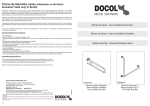
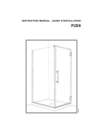
S
UNNPRO
Sp Series
Manual
Congratulations on purchasing a SunnPro Solar Collector.
These Sp series vacuum tube solar collectors are amongst the most efficient solar collectors
available.
Vacuum tube solar collectors use a series of highly efficient glass vacuum tubes, that collect
the sun’s energy and turns it into heat that can be used in your application. The vacuum tubes
are specially adapted and treated to collect different types of the sun’s energy, protecting the
heat from loss back to the atmosphere and then transferring the heat in to your solar circuit via
a heat-pipe.
Applications of these Sp series vacuum tube collectors include heating of domestic and
commercial hot water, buildings, and swimming pools.
SunnPro Sp solar collectors have been manufactured to the very highest standards, and will
provide you with many years of service, with the minimum of maintenance.
Before assembly and installation, please read this manual carefully.
www.sunnpro.com
S
UNNPRO
Sp Series Technical Data
No Tubes
Width mm
Height mm
Depth mm
Sp10
10
854mm
2010mm
145mm
Sp15
15
1275mm
2010mm
145mm
Sp20
20
1680mm
2010mm
145mm
Sp25
25
2050mm
2010mm
145mm
Sp30
30
2420mm
2010mm
145mm
Sp10
Sp15
Sp20
Sp25
Sp30
Total area
1.17 m²
2.56 m²
3.38 m²
4.12 m²
4.90 m²
Aperture area
0.936 m²
1.395 m²
1.860 m²
2.326 m²
2.791 m²
Absorber area
0.808 m²
1.206 m²
1.607 m²
2.009 m²
2.411 m²
Dry Weight
39.6 kg
54.8 kg
73 kg
91.5 kg
106 kg
Fluid Volume Manifold
0,7 l L
1,07 L
1,4 l L
1.85 L
2,3 l L
Recommended Flow
Rate
Wind resistance
Hail resistance
1.08 / 1.62 1.61 / 2.41 2.14 / 3.21 2.68 / 4.02 3.21 / 4.82
L/min
L/min
L/min
L/min
L/min
up to 108km/h (67.1mph) (30m/s)
Up to 30mm
Mechanical and hydraulic data
Working pressure
max. 6 Bar
Recommended flow rate
3.5/8 Ltrs/M²h
Hydraulic connections
1” Male Screw
Absorber & Collector
Sizes of tube
Ø58mm x 1800mm
Wall thickness of tube
1.8mm
Glass material
High quality borosilicate glass
Solar Selective Coating
AIN/AIN-SS/CU (Three Layers)
Stagnation temperature
200.3°C
Emission co-efficiency
<0.06 for 80°C
Vacuum
<=3 x 0.001Pa
Solar Absorptance
94% to 96%
Manifold
Aluminium alloy
Supporting stand
Aluminium alloy
Frame
Aluminium alloy
Sealing material
Silicone rubber
Exchanger material
Copper
Insulation
Polyurethane, Mineral wool
Heat-Pipe Condenser
Ø24mm
Recommended Tilt Angle
15°- 75°
SUNNPRO
Solar Collector Pressure Drop Curve
Based on Sp30
Mass Flow [Kg/h] 0 100
0
6.9
200
300
400
500
600
700
22.7 47.2
80.5
122.7
173.7
800
900
233.4 302 379.4
[mbar]
Independent Performance Data
Output in Watt
400[W/m²]
700[W/m²]
1000[W/m²]
Tm-Ta
(K)
Sp10
Sp30
Sp10
Sp30
Sp10
Sp30
10
259
772
465
1387
671
2001
30
218
650
424
1264
630
1879
50
164
490
371
1105
577
1719
SUNNPRO
Sp Series Installation
The solar collector is suitable for installation on flat roofs, tiles roofs, cement/concrete roofs etc. The
installation should only be carried out by qualified solar technicians. Please review any applicable local
norms and regulations before mounting and operating the solar system.
Building Structure
The collectors may only be mounted on sufficiently load-bearing roof surfaces and substructures. When
installing on an existing roof structure, ensure that the substructure is sufficient to support the additional
weight. It is essential that the structural load-bearing capacity of the roof and the substructure must be
tested at the installation site before mounting the collectors.
Particular attention should be paid to the quality of the (timber) substructure in terms of the stability of the
screw fixings necessary for installing the collectors. In particular, it is essential to have the entire collector
structure verified at the installation site according to country-specific regulations in regions with heavy
snowfalls and strong winds. The assessment should also take into account any special features of the
particular site that could lead to increased loads (for wind, air jets or eddy formations, etc). Collector arrays
should always be installed in such a way that any possible snow piles do not reach the collectors. There
must be at least 1m distance from roof ridging or edges. The solar collector needs to be installed with a
strong sturdy fixing to a solid structure. It is not advisable to fix with flexible straps passed under tiles.
This type of fixing can lead to excessive vibration from wind and lead to damage
When planning the installation, ensure you have considered the fixing method with regard to your roof
structure, pipe runs and pipe penetrations in the roof section. All of these connections will need to offer
protection from water penetration caused by wind pressure and driving rain / snow.
Lightning protection / Equipotential bonding of the building
It is not necessary to connect collector arrays to the lightning protection of the building (please observe
the country-specific regulations). For installations on metal substructures at the installation site, authorized
lightning protection specialists must be consulted. It is possible to ground the collectors to a ground rod.
The grounding line must be laid outside the building. The ground rod must also be connected to the main
potential equalization conductor by a line with the same cross-section. It is advisable to install protection
diodes for the solar collector temperature sensor, this will protect your control device from over voltage
induced by lightening.
Connections
The collectors must be connected with one another and/or the system connection pipes using screw
connection and not soldered joints. Soldering on solar collectors is not recommended because of the
potential damage to the collector manifold. The collector in let and outlet is 1” Male.
If you do not intended to use flexible pipes as connecting elements, precautions must be taken to protect
the connection pipes against temperature fluctuations caused by heat expansion (expansion bends/flexible
piping).
No more than 6 collectors (Sp20) or 4 collectors (Sp30) may be connected in series, Without the use of
expansion connections, for connecting the collectors together.
Collector inclination
The collector should be installed at angles between 15° (minimum) and 75° (maximum). This is for the correct
operation of the heat-pipe.
S
UNNPRO
Installing the temperature sensor
The temperature sensor should be installed in the sensor sleeve nearest to the collector array flow to the hot
water store. To ensure optimal contact between the sensor and the sleeve, smear the sensor element with a
suitable heat transfer paste. All materials used for installing temperature sensors (sensor element, cables,
conducting compound , sealing and insulating materials) must be suitably temperature resistant (up to 250°
C). It is advisable to install an IP65 Connection Box with overvoltage protection diodes. These diodes will
protect your controller from induced voltage spikes caused by local lightening.
Sp Series Operating
Filling
For reasons of safety, you should only fill the collector circuit when there is no direct irradiation from the sun
(or cover the collectors) . In regions exposed to frost, you should use a premixed antifreeze complete with anti
corrosion inhibitors.
It is impossible to completely empty collectors once they have been filled. For this reason, collectors exposed
to frost should only be filled with antifreeze, also for pressure and function tests.
We recommend to fill the system with a pressure filling pump to eradicate any air bubbles within the manifold
and solar circuit.
Operating pressure
The maximum test pressure is 10 bar. Operating pressure is 6 bar.
Air vent
The system must be bled when commissioning the system (after filling the system / collectors) or if there are
malfunctions. !Caution! Do not work on the system when hot because of the risk of scalding due to steam
and hot heat transfer fluid! Cover the tubes with a blanket and wait for the system to cool.
Only operate the air vent valve if the temperature of the heat transfer fluid is < 60° C.
Check heat transfer fluid
It is recommended to fill the system / collector with an antifreeze
The heat transfer fluid must be checked every two years with regard to its antifreeze and pH value.
- Check antifreeze using antifreeze tester and replace or refill if necessary.
Target value approx. -20° C depending on climatic conditions.
- Check pH value with a pH indicator rod (target value approx. pH 7.5):
If the limit pH value is less than
pH 7, replace the heat transfer fluid.
Maintenance of the collector
The collector or the collector array must be inspected visually, once a year, for any damage, leaks and
contamination. At this time visual inspection of the base of each vacuum tube is necessary to ensure the
vacuum integrity. If the base of the tube is silver in colour then the vacuum is present in the tube. If the base
has turned white / translucent colour then the vacuum has be lost and a replacement tube should be installed.
S
UNNPRO
Sp Series Packing Shipping & Handling
All SunnPro Sp Series collectors are supplied in cartons and are
very simple to assemble.
Storage of these cartons must be on a level flat surface, and the
entire base of the cartons must be supported.
Cartons should not be stacked more than 5 high and should be lifted
by two people because of the carton size.
Transporting.
Transporting these products, particularly the tube cartons should be done with extreme caution. When
transporting via road, it is advisable to transport with these cartons secured to a pallet.
Example Packing Contents for SP30
58TUBE-15
58TUBE-15
SP30 FRM
SP30 MAN
Carton Contents:
Glass Evacuated Solar Collector Tubes: Cartons 15 or 10 pcs containing Vacuum tubes and
heat-pipes.
Heat Pipe Solar Collector Frame: Carton contains the fixing frame, tube cups, nuts & bolts.
Heat pipe Solar Collector Manifold and Tail Stock: Carton contains heat exchange manifold
and lower tube support bar.
Model
Manifold
Fixing Frame
Tubes
Tubes
Sp10
SP10 MAN
SP10 FRM
58TUBE-10
Sp15
SP15 MAN
SP15 FRM
58TUBE-15
Sp20
SP20 MAN
SP20 FRM
58TUBE-10
58TUBE-10
Sp25
SP25 MAN
SP25 FRM
58TUBE-15
58TUBE-10
Sp30
SP30 MAN
SP30 FRM
58TUBE-15
58TUBE-15
SUNNPRO
Assembly of the Solar Collector
Firstly, it is important to understand the basic operation of the heat-pipe solar collector.
Each of the heat-pipes works independently to collect and deliver heat to the exchanger in the
manifold.
The role of the glass vacuum tube is to collect the sun energy and protect this heat from loss back to
the atmosphere. This is done via the special coatings and vacuum in the tube. Heat is then transferred
to the heat-pipe via an aluminium fin inside the tube. The role of the heat-pipe is to transport the heat
to the exchanger in the manifold.
The condenser (large end of the heat-pipe)
inserts though the heat-exchanger, but does not
actually come into contact with the passing
heat transfer fluid. The heat passes from the
heat-pipe to the copper material of the
exchanger and then into the passing fluid. This
is an important point to understand should you
need to change a tube and heat-pipe in the
future. Tubes and heat-pipes can be changed
without draining the system.
Assembly
To assemble the collector frame, simply connect the vertical frame sections to the
manifold. This is best achieved by laying the manifold face down on a soft surface
(Blanket). Remove the nuts from the studs protruding from the rear of the of the manifold
place over the vertical aluminium frame sections and
Secure the nuts hand tight at the moment.
Next, fit the tail stock whilst the frame is upside down using the M8 nuts
& bolts provided. On the Sp10 and Sp15 there are two vertical frame
sections & three on the Sp20, Sp25 & Sp30 models. Secure the nuts
hand tight at the moment.
Next, fit the smaller channel sections across the horizontal sections of
the collector, these horizontal supports are located under the collector
and are secured using the M6 nuts and bolts provided.
Next, you now need ensure the assembly is square before final tightening, this is easily achieved using
the edge of a rug for example (if you are assembling on a rug) or any other squared edge. Once the
assembly is square, tighten the nuts and bolts.
SUNNPRO
Once you have
completed these steps
you can position your
collector frame and
fix using an
appropriate fixing
method.
When you have complete the fixing of the frame, it is advisable to connect the plumbing and fill the
system. When the system is ready for operation insert the tubes. The tubes can be installed at the time of
fixing the collector frame, but extreme caution must be taken when working on the system because of
potential heat transfer through the piping.
Inserting the tubes.
Prepare the tubes for inserting into the collector manifold, coat a
thin layer of heat transfer paste over the condenser part of the
heat pipe. After this apply soapy water to the tube ends a shown
in the picture.
Next slide over the rubber ring, which is the seal between the
tube and manifold.
Using a twisting motion, insert the tube into the manifold, place the supporting cup over the end of
the tube and clip the supporting cup into the tail stock.
Slide the rubber ring up to form a seal between the manifold
And the tube.
Repeat the process for the
remaining tubes.
Your solar collector is now
installed and ready for use.
After filling and operating the system
ensure the collector connections are
free from leaks.
Distribution Partner
European Agent: Solar Shop Europe Ltd
UK: 0044(0)20 81232921
Ire: 00353(0)766024120
France: 0033 (0)468 055906
UNNPRO
S
Sp - Series Warranty
SunnPro (Manufacturer) and Solar Shop Europe Ltd (“Importer and/or person responsible within EU”) guarantee that products
at which these warranty conditions are applied to, are without manufacturing defects, were tested, completeness was revised,
and they are conformable to relevant norms, which they are pertinent to.
1. General warranty conditions.
Warranty is relating to manufacturing defects only.
Warranty period commences on the date of sale of the product. Time duration of warranty is 10 years from invoice date .
“Importer” reserves the right to examine the products under complaint.
Reclaimable products under claim will be remedied by repair or by exchange within warranty at the expense of the
“importer” within the duration of 30 days. Arrangement and place of repair under warranty is determined by Importer.
Condition to exercise this warranty is completely filled warranty form, confirmed certificate of warranty and all
receivables paid in full for products.
Warranty expiry and restriction
Entitlement for warranty expires, if the product is damaged by the use of incorrect handling and transportation of the
products by the buyer namely:
Unprofessional storage and transportation
Unprofessional assembly
Product usage for other purposes than what it was intended for
Product operation which is in variance with service manual
If the product was effected by intervention or changes by the customer or any other wrongful person or organization
Warranty is not relating to claims caused by penetration of foreign matters into the product except manual servicing and
heat transfer fluid with corrosion inhibitors with defined chemical and physical properties
Demand for warranty expires, if the product assembly, its placement and/or connection, does not conform to the
instruction manual, professional best practice.
Demand on warranty expires if required assembly of the product is not fulfilled in compliance with installation manual or
operating instructions and/or all relevant norms, practical manuals, safety requirements or regional regulations.
Warranty is not relevant to claims incurred from transport of the products
If entitlement for warranty was unjustified, claimant bears all costs connected with file of the claim of this warranty
Entitlement for warranty expires when warranty period lapsed
2. Limited warranty for selected products.
2.1 Solar collectors.
The condition of this warranty is, that solar collectors were installed by an assembly crew, organisation which is in possession
of valid certificate for product installation and have completed successful training.
Entitlement for warranty of solar equipment expires:
If, unto defects, malfunctions of solar equipment and consequential damages following usage of incorrect solar
equipment, by unskilled installation and connection of solar equipment especially:
Damage of the collector at installation.
Damage of collector following incorrect mounting or erection of base on which the equipment are mounted.
Breakage of glass parts of the collector or the heater at installation.
Loss of vacuum in the heat pipe or its burst because of excessive mechanical or thermal stress.
If solar collectors were transposed from place of original installation.
Improper accessories were used for the solar system, mainly improper solar regulator/controller which is unable to
prevent thermal shocking of the collector.
Warranty Exclusions
S
UNNPRO
The warranty does not apply to the following conditions or circumstances:
Lightning damage, atmospheric electricity damage or Act of God
Damage to buildings and their structural attachment by leakage of cooling liquid or water at any connections of the
solar equipment.
Damage to solar equipments by welding and/or soldering on solar equipment.
Loss of tightness, damage of the solar equipments following mechanical strain of hydraulic supply and construction
of solar equipment.
Loss of tightness, damage of the solar equipments following weariness of material due to periodical mechanical
strain of hydraulic supply and/or construction of the solar equipment.
Loss of vacuum in the thermal tube or its rupture following excessive mechanical or thermal strain.
Damage of solar equipment following freeze over of cooling medium or water in the solar equipment.
Damages incurred by environmental forces notably:
By wind.
Excess load by snow cover and/or by ice.
Falling objects onto the solar equipment.
Damages on solar equipment because of its placement in aggressive surroundings, operation and/or its exposure to
combustion products, namely:
Corrosion of parts of the solar system
Colour changes, change of colour finish of solar equipment.
Colour changes, change of colour finish of solar equipment following environmental effect
Electrolytic corrosion of parts of the solar equipment following inept selection of components of the solar system or
the effect of leakage of electric current.
3. Application of Warranty.
To exercise this warranty. Reported defects must be reported in written form to the seller informing where the product was
purchased. Part of the written report must have dated photo documentation of the product with properly documented reports
to the extent of the defect. Products in claim to exercise the warranty must be stored at the purchaser’s for duration of not less
than 90 days and must be ready for possible inspection by Manufacturer/Importer.
4. Final Provisions.
Manufacturer and Importer disavows from any demands for any consequential, exemplary, randomly, penalty, special,
speculative or other alike defects, property damage included or compensatory of property resulting from breach of Certificate
of Warranty or any other defects.
Importer will not be liable to any party, including the customer, for any consequential, exemplary, incidental, indirect,
liquidated, punitive, special, speculative or other similar damages, including, without limitation, any damages to property or
cost of replacement goods, resulting from any breach of warranty by a product or any product defect. Importer reserves the
rights for completing, explication or changes of this Warranty.
These Warranty conditions are not surety for sales of solar equipment, its components for their applicability for individual
purposes, guarantee for mistakes, violation by any other party, any warranties against infringement of rights of other party in
the sphere of intellectual property and judicial cognizance.