1
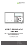
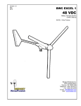
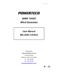
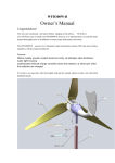
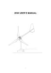
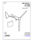
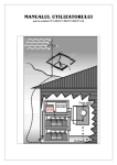
500W 24VDC
Wind Generator
User Manual
MG-4540
Distributed By:
Electus Distribution Pty Ltd
320 Victoria Road
Rydalmere, NSW 2116 Australia
Tel : 1300 738 555
Fax: 1300 738 500
www.electusdistribution.com.au
Table of Contents
1.
Safety Precautions
3
2.
Preliminary Overview
5
3.
System Description
6
4.
System Operation
7
5.
Turbine Installation
8
6.
Electrical Connections
11
7.
Maintenance - Monthly
12
8.
Maintenance - Yearly
12
9.
Trouble Shooting
13
10. Limited Warranty
14
11. Specifications
14
-2-
FD500W 24VDC 500W
Wind Generator
1.
Safety Precautions
Please follow the instructions and recommendations in the User Manual. This will help assure
safe and rewarding use of your new renewable energy system.
WARNING!
It is essential you read the entire contents of the User Manual prior to
installation and operation.
Wind generator (or wind turbine) systems present mechanical, electrical and chemical
(battery) hazards that can be life threatening. The generator, tower or support structure could
fall and cause injury or death and property destruction. A component of the wind generator
could become loose, causing injury or death. If the wind generator is connected to a DC to AC
power inverter, then high voltages from the inverter could cause injury or electrocution. A burn
injury can result from an electrical short. A severe chemical burn, including blinding, can
occur from a battery explosion or contact with the sulphuric acid in a lead-acid battery.
-3-
These conditions are addressed in the following safety messages:
WARNING! It is your responsibility to obtain all required permits and engineering
certifications for your tower, guy wires and tower location. Professional advice should be
obtained. Soil and wind conditions vary from area to area and tower foundations, including the
tower/ mast configuration, must be designed for dynamic wind loading that is specific to the
area. The tower must be positioned so that it can not fall on occupied buildings, neighbour’s
property or power lines. The manufacturer recommends locating the tower well away from
occupied buildings and power lines ie typically 100m minimum. Tower climbing is dangerous
and should only be attempted by experienced and qualified personnel using proper safety
equipment.
WARNING! If the generator appears to be loose or vibrate in the tower, or is making an
unusual sound, the condition must be rectified immediately. A loose generator or component
presents an extremely dangerous situation as it may fall from the tower. Never stand in line
with a rotating propeller.
WARNING! It is strongly recommended you install protection barriers to prevent
unauthorized persons or children climbing the tower. Never allow an untrained person or
someone without the proper safety equipment to climb the tower. Choose a calm, dry day for
your installation and always stop the propeller before climbing the tower. Falling from the
tower and contact with the rotating blades can be lethal.
WARNING! High voltage systems (systems with an inverter) represent a dangerous shock
hazard and could be lethal. All high voltage systems should be wired and maintained by a
qualified and licensed electrician.
WARNING! Batteries can emit dangerous and explosive gas while charging. Never turn on a
light switch or any other electrical connection near a recently charged or charging a battery.
Never light a match or make any type of spark near a recently charged or charging battery.
Use protective gloves and eyeglasses when working with lead-acid batteries. Remove all
personal metal items such as rings, bracelets, necklaces, and watches when working with
lead-acid batteries. A lead-acid battery can produce short-circuit currents high enough to weld
a ring or similar metal, causing a severe burn. Turn off all loads and be extremely careful
when making a final battery connection.
WARNING! Never place objects on top of, or near the charge controller, inverter, aurora
wind interface when applicable. These devices dissipate heat and require unrestricted airflow
as part of normal operation. FIRE AND FAILURE can result if airflow is blocked.
WARNING! To reduce the risk of fire or electric shock, make sure the installed wiring and
terminations are in good electrical condition and that all cables are appropriately sized to
carry the necessary charge currents.
WARNING! To reduce the risk of electric shock, do not operate the wind turbine without
connecting it to an appropriate ground. Grounding procedures must be followed along with
any regulatory codes. Grounding the tower is essential for lightning and static protection.
Disclaimer
Unless specifically agreed to in writing, we:
(a) Make no warranty as to the accuracy, sufficiency or suitability of any technical or other
information provided in this manual or other documentation.
(b) Assume no responsibility or liability for loss or damage, whether direct, indirect,
consequential or incidental, which might arise out of the use of such information. The use
of any such information will be entirely at the user’s risk.
-4-
2.
Preliminary Overview
The FD500W wind generator is a state of the art 500W alternator/ charge controller system
designed to charge batteries and supply electrical power in a 24VDC system. When used in
conjunction with a suitable sine wave DC to AC inverter and a battery bank, the FD500W can
also provide high voltage AC for powering mains type AC appliances.
The FD500W features superior low wind speed performance, very high system efficiency, and
low noise.
Charge Controller
+
Wind Generator
Fuse
POS +
NEG 24VDC Battery Bank
2.1 What you should have with the FD500W
1
1
3
1
1
1
1
Qty
1
Tail fin
Tail boom
Rotor blades
Alternator with output cables
Hub for mounting rotor blades
Nose cone
Charge controller
Fasteners (nuts, bolts, washers, split pins, etc)
User Manual
-5-
3.
System Description
The major components of the FD500W wind generator are shown as below.
3.1 Rotor and Blade System
The rotor and blade system consists of three fibreglass blades fastened to a hub. The rotor
blades convert the energy of the wind into rotational forces that drive the generator. The
fibreglass blades are exceptionally strong, however, they may be damaged if they come in
contact with a solid object.
3.2 Alternator
The FD500W wind generator is a horizontal axis wind generator that mounts to a vertical
pole/ tower. The wind generator consists of an alternator that utilizes extremely strong
permanent magnets to produce electricity.
The alternator produces a three-phase alternating current (AC) output which is rectified into
direct current (DC) by the charge controller. Note, since the alternator uses permanent
magnets, it will generate electricity/ voltage whenever the rotor is turning.
3.3 Nacelle
The nacelle is the aluminium housing that surrounds the main body of the wind generator. It
contains the main structural backbone of the turbine (called the mainframe), the yaw bearings,
and the tower mount. The yaw bearings allow the wind turbine to freely pivot around the top of
the tower so that the rotor faces the wind at all times.
3.4 Tail Assembly and AutoFurl Operation
The tail assembly, which comprises a tail boom and the tail fin, keep the rotor blades aligned
into the wind at wind speeds below approximately 12.5 m/s. At about 12.5 m/s the AutoFurl
action turns the rotor away from the wind to limit its rotational speed. The tail appears to fold,
but in reality the tail stays stationary, as the rotor/ alternator angles away from the wind. The
rotor does not furl completely, as this allows the turbine to continue to produce power in high
wind speeds. When the high winds subside, the AutoFurl system automatically restores the
turbine to the normal unfolded or straight- configuration.
-6-
3.5 Charge Controller
The charge controller serves as the central connection device for the electrical components of
the system. The charge controller has two primary functions:
•
•
rectifies the AC output from the alternator into DC, and
charges the battery bank
The controller continually monitors the battery voltage and compares it to the regulation set
point. The regulation set point is factory set to 30VDC for a 24VDC wind generator. When the
battery voltage rises above the set point, it automatically stops charging the batteries. It then
waits for the battery voltage to drop slightly below 22VDC before normal charging resumes.
WARNING! Bad connections and terminations, undersized cables, excessive cable lengths
and in-line isolation diodes (blocking diodes) will prevent the charge controller from working
properly.
3.6 Battery Bank Capacity
We recommend two 12V/200Ah normal lead-acid batteries for the 500W/24VDC system.
4.
System Operation
4.1 Normal Operation
The rotor blade assembly of the FD500W wind generator should begin to rotate when the
wind speed reaches approximately 3m/s. For the first several weeks of operation, the start-up
wind speed will be slightly higher because the bearing seals take a short period of time to
wear in. Battery charging should commence shortly after the rotor spins up to speed. Once
the rotor assembly is turning, it will continue to do so in lower wind speeds, typically down to
approximately 2.5m/s.
Rotor speed increases with increased wind speed. This results in the wind generator
providing a higher output. The output increases rapidly because the energy available in the
wind is a function of the third power (cubed power) of the wind speed. For example, if the
wind speed doubles from 5m/s to 10m/s, the energy in the wind increases by a factor of eight
ie 23 = 2 x 2 x 2 = 8.
One disadvantage of this relationship is that there is very little energy available in light winds.
For the average site, winds in the range of 5.5m/s to 12m/s will provide most of the system
annual energy production.
4.2 High Winds – Autofurl
During periods of high wind speeds, the AutoFurl system will automatically protect the wind
turbine. When furled, the power output of the turbine will be significantly reduced. In winds
between approximately 13m/s and 18m/s it is normal for the turbine to repeatedly furl, unfurl
and then furl again. In winds above 18m/s the turbine should remain continuously furled.
AutoFurl is a simple and elegant method of providing high wind speed protection. The
AutoFurl system is based on aerodynamic forces on the rotor, gravity, and the carefully
engineered geometry of the wind turbine. As shown in the following illustration, the
aerodynamic forces acting on the blades cause a thrust force pushing back on the rotor. This
force increases with increasing wind speeds. The thrust force acts through the centreline of
the rotor, which is offset from the centreline of the tower pivot/ axis (yaw axis). Therefore, the
thrust force on the rotor is always trying to push the rotor over to the side, away from the wind.
-7-
But the rotor blade assembly is kept facing into the wind at speeds less than 12.5m/s by the
wind turbine tail assembly. The tail is kept straight by its own weight, and because the pivot at
the back of the nacelle is inclined. So the weight of the tail holds it against a rubber bumper
and the tail holds the rotor into the wind.
The geometries in the systems are carefully balanced so that at a wind speed of 12.5m/s the
rotor force acting on the yaw-offset is large enough to overcome the preset force holding the
tail straight. At this point the rotor will start turning away from the wind, or furl, and the tail will
stay aligned with the wind direction. The speed of furling depends on the severity of the wind
gusts and whether the wind turbine stays furled depends on the wind speed.
As the wind turbine furls the geometry of the tail pivot causes the tail to lift slightly. When the
high winds subside, the weight of the tail assembly returns the whole turbine to the straight
position. The AutoFurl system works whether the turbine is loaded or unloaded.
The AutoFurl system is completely passive, and reliable since there are no wear points.
WARNING! There is one situation in the field, however, that can disrupt the operation of
AutoFurl. If the wind turbine is installed on a sharp hill or next to a cliff so that the wind can
come up through the rotor on an incline (e.g., from below; as opposed to horizontally) it will
effect furling and can produce higher peak outputs. We strongly recommend avoiding this
situation.
The wind generator is designed to survive in wind speeds of up to 30m/s (108km/hr).
5.
Turbine Installation
When installing the FD500W, exercise care at all times. The turbine weighs 15kg and ican be
awkward to handle. It is best to plan the installation carefully in advance and use qualified
personnel when erecting the machine and tower to avoid accidents.
NOTE: Complete as much of the installation as possible at ground level.
NOTE: Choose a calm, dry day for your installation.
-8-
The FD500W is robustly engineered, but contains high-energy permanent magnets that can
be easily damaged from impacts if the machine is dropped or heavily handled.
CAUTION! Make sure the turbine is disconnected from the charge controller and batteries
during installation.
Selection of tower and rigging materials is important. Avoid connecting different metals
together ie copper and aluminium as this will create an electrochemical reaction or galvanic
cell that will eventually erode one of the metals.
NOTE: All external electrical cables should be protected to prevent damage from wildlife.
Run all wires inside conduit for protection.
Step 1: With the tower tilted down, place the powerhead of the wind turbine near the top end
of the tower.
Step 2: Raise the tower about 1 metre off the ground to allow space to assemble the turbine.
We recommend using a temporary support stand to hold the tower up during turbine
assembly.
Step 3: If not already done, remove a small amount of insulation from the three generator
wires. Then conduct the following electrical tests.
Step 4: Now run three extension wires from the generator down inside the tower to the
charge controller location before mounting the powerhead assembly to the tower.
Step 5: Join the generator output wires to the extension wires running inside the tower using
high current waterproof connectors or solder. If soldered, use heat-shrink tubing, self
amalgamating tape or similar to insulate and protect. The connections should be
waterproof to minimise the possibility of oxidation and failure.
-9-
Step 6: Electrically short all three extension wires at the charge controller end with a small
piece of wire to prevent the generator from turning and producing power. Note: the
short-circuit wire must be removed during the electrical installation stage later on.
Step 7: Gently pull the three wires down through the tower, being careful not to damage or
pinch the cabling. Then mount the powerhead to the top of the tower. Check the
powerhead is securely mounted to the tower as is has to hold firmly in high velocity
winds.
Step 8: Using a torque wrench, tighten all powerhead/ tower mounting fasteners to 54Nm.
Step 9: Bolt the tail fin to the tail boom.
Step 10: Place the tail boom on the rear of the turbine powerhead and insert the tail pivot pin
from the top.
Step 11: Attach the rotor blades to the hub with the red coloured tips facing the front, or
oncoming wind direction, using the M10 hardware provided. Bolt one blade up solidly
and leave the other two somewhat loose ie finger tight.
Step 12: Carefully slide the rotor blade assembly onto the generator shaft. Place the washers
and nut on the generator shaft and tighten.
Step 13: Accurately check the tip-to-tip blade distance and adjust as necessary so they are all
equal. This will optimise configuration, alignment and balance of the blade assembly.
Tighten all blade nuts once balanced.
Step 14: Carefully place the nose cone over the hub and rotor blade assembly. Insert the
screws and tighten.
Step 15: Carefully raise the tower making sure not to damage the wind generator; especially
the blades and rotor assembly. Secure the tower firmly with guy wires as required.
- 10 -
6.
Electrical Connections
The general electrical configuration or setup is illustrated in the previous section. In most
cases the loads will be 240VAC and will obtain power through a DC to AC power inverter.
The charge controller must be installed in a waterproof cabinet or indoors, and should be
located relatively close the battery bank to minimise cable losses.
WARNING! Do not install the charge controller outdoors without protection; it is not
waterproof.
WARNING! Connect the battery first to the charge controller.
Step 1: Connect the battery leads to the charge controller. First connect the negative (-)
battery wire to the negative (-) terminal on the charge controller. Connect the positive
(+) wire to the charge controller, then “Touch” the positive (+) terminal of the battery
and withdraw quickly. If a very large spark occurs, the connections are reversed.
Check wiring configuration if this occurs. Connect the positive (+) charge controller
wire to the positive (+) terminal on the battery.
WARNING! The user must connect batteries to the wind generator system. Without the
batteries connected, the wind turbine may be damaged after some time!
Step 2: Remove the shorting wire from the three extension wires. Connect the three wind
turbine leads to the three terminals on the charge controller. The three wires are
interchangeable and therefore are not labelled. Any leads can go to any terminal.
Step 3: If the system includes a DC to AC power inverter, connect the inverter DC input leads
to the battery terminals, not to the charge controller. The controller circuit board is not
designed to handle the high currents that are possible when power inverters are fully
loaded. Inverters can draw extremely high currents, hence the reason they should be
directly and securely connected to the batteries with appropriately sized cables. Refer
to suppliers recommended cable sizes.
WARNING! Do not connect the wind generator directly to an inverter without batteries. The
inverter will not work and may suffer permanent damage.
WARNING! Do not disconnect the batteries while the inverter or wind generator are running.
Permanent damage may occur.
Ensure that you have the correct battery size, voltage and capacity for your system. The
FD500W wind generator utilises a 24V battery system. Ensure that the batteries used are
identical types and of identical age. Mixing different types/sizes/ages of battery will cause all
the batteries in the bank to fail prematurely. If you need to replace batteries, you should
replace all at once.
WARNING! If it is necessary to disconnect the generator for some reason, do so before
disconnecting the battery from the charge controller.
- 11 -
7.
Maintenance - Monthly
7.1 Wind Generator
Check the wind generator monthly for mechanical noises, rattles, buzzes or vibration. These
conditions can be damaging and should be investigated and addressed. It is essential the
rotor blades are balanced and do not wobble. If the blades or the wind generator wobble it
must be rectified immediately.
7.2 Tower
Undertake all maintenance requirements outlined by the tower manufacturer/ supplier. Inspect
the tower thoroughly including guy wires and foundations. Tighten all nuts and bolts,
especially wire clips. Check for cracks, bent or broken parts and inspect the anchors and
tower base structure. Check for broken strands and tighten guy wires.
7.3 Charge Controller and Batteries
Consult the battery manufacturer’s maintenance guide and follow the instructions for period
maintenance. Check and tighten all electrical connections on the charge controller and
batteries. Remove any corrosion and protect the terminals.
8.
Maintenance - Yearly
8.1 Wind Generator and Tower
Lower the tower and thoroughly inspect the wind generator. Fix or replace any worn,
damaged or loose parts. Check and tighten all mounting nuts and bolts. Check and tighten all
rotor blade mounting bolts. Check the bearings for ‘play’. Just perceptible ’play’ is acceptable.
Clean the blades with a mild detergent to remove all dirt and debris. Avoid scratching the
surface.
Replace rotor blades if they are cracked or damaged in any way.
- 12 -
9.
Trouble Shooting
The following table should be used as a guide to pinpoint the cause of any operational
problems.
Problem
Battery
voltage gets
too high.
Cause(s)
Charge controller
output voltage
regulation too high.
Batteries do
not reach full
state of
charge.
Charge controller
output voltage
regulation too low.
Rotor spins,
but the
system does
not charge
the
batteries.
Rotor is
unbalanced,
causing the
turbine to
vibrate or
move back
and forth as
it spins.
Diagnosis
Excessive battery gassing. Use a
precision DC voltmeter to check
battery voltages. Use a hydrometer to
check the specific gravity of the
battery acid if applicable. Compare
results to battery manufacturer’s
recommendations.
Battery not providing enough power.
Use a precision DC voltmeter to
check battery voltages. Use a
hydrometer to check the specific
gravity of the battery acid if
applicable. Compare to battery
manufacturer’s recommendations.
Remedy
Contact factory or
distributor and replace
charge controller.
Cable losses too
high.
Check cable sizes (ie gauge size) and
cable runs. Cable sizes too small or
cable runs too long. This can result in
excessive voltage drops.
Increase cable size (ie
reduce gauge) or
shorten cable runs.
Connector or
termination losses
too high
Check connectors and terminations.
Loose connectors and terminations
can cause voltage drops, as well as
localised heating.
Properly secure
connectors and cable
terminations.
Loads are too
large.
Remove largest load and check if the
battery bank now reaches full state of
charge. If so, the system was
overloaded.
Reduce loads
Insufficient wind
power
Blown output fuse
System not providing enough power.
No remedy
Remove the fuse in the charge
controller and check with a multimeter
Replace fuse
Turbine rectifier
failure, possible
damaged stator
winding, damaged
charge controller
Blade tips not
evenly spaced ie
blades are out of
balance.
Check wind generator AC output
voltages to charge controller. Check
DC output voltage from the charge
controller with a DC voltmeter.
Replace charge
controller, or wind
generator powerhead
as necessary.
Accurately check the blade tip-to-tip
distances. The tip-to-tip distances
should all be equal.
Loosening one blade at
a time, adjust the tip-totip spacing so that they
are all equal. Check
that the rotor blade
assembly if evenly
balanced.
- 13 -
Contact factory or
distributor for repair.
10. Limited Warranty
We provide free replacement cover for all defects with respect to parts and workmanship for a
period of two years from the date of purchase. Our obligation is limited to replacing parts
which have been promptly reported to the seller as having been in his opinion defective, and
are so found by us upon inspection.
Defective parts must be returned to us as soon as possible, or to an authorised agent.
This warranty is void in the event of damage due to improper installation, owner neglect,
blade damage resulting from flying objects, or natural disasters such as lightning, extreme
winds, and does not extend to any additional devices connected to the system.
This warranty is also void if any modifications are carried out on the wind generator.
No responsibility is assumed for incidental or consequential damage, damage caused by the
use of any unauthorised components.
11. Specifications
Model No.
FD500W
Rated Power
500W
Maximum Power
600W
Rated DC Output Voltage
24V
Start-up Wind Speed
3m/s
Rated Wind Speed
8m/s
Maximum Wind Speed
20m/s
Cut-Out Wind Speed
12m/s
Over Speed Protection
Auto Furl
Temperature Range
-40 to +60 Deg. C
Rotor/ Blade Diameter
2.5m
Rotor speed
400rpm
Blade material
Fibreglass
Height of tower (Recommended)
Generator
6m
3 phase permanent magnet alternator
Weight of turbine
15 kg
- 14 -