1
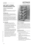
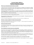
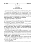
E100 FABRIC DOOR
(Motor operator & fullVisison panel)
SERVICE DOOR INDUSTRIES LIMITED
1340 MIDWAY BLVD., MISSISSAUGA, ONTARIO,
CANADA L5T 2G8 TEL (905) 670-1200 FAX (905) 6708830 [email protected]
PREFACE
The main purpose of this manual is to assist with the installation and maintenance of your new E100 Fabric Door
system with the emphasis on proper installation procedures, safety of operation, and replacement parts list. While
various construction and electrical procedures are outlined, please refer to particular codes for you area.
INTRODUCTION
DOOR PARTS
The Shop Drawing on the following page shows the major components of the E100 Fabric Door. (For more
detail, please refer to the parts list near the end of this manual.)
Please define all parts by the names shown on this drawing and throughout this manual. When technical
information and or replacement parts are required, please provide the following data to ensure prompt and
efficient service.
1) The SERIAL NUMBER of your door system 2) The
OPENING SIZE (width x height) 3) The TYPE & HANDING
OF OPERATOR (left or right) 4) The operator motor voltage
INSTALLATION INSTRUCTIONS
STEP “A” – PREPARATION OF THE DOOR OPENING
Although the actual mounting procedures are different between steel and masonry walls common prerequisites are
required for all door systems.
All door systems will require a certain amount of headroom and side room clearances. See Shop Drawing
supplied with each door for specific details
All door systems must be mounted level. Draw a reference line at a distance equal to the overall height of the guide
above the floor extending to the extremities of the side room clearances. Take extreme care to ensure that this line
is straight and level because the entire door is positioned according to this reference line. A transit or water hose
level is recommended.
All mounting surfaces must be flat and flush to each other.
STEP “B” – INSTALLING THE DOOR GUIDES
Regardless of which way YOU decide to attach the Guides to the existing wall (typical cross sections of Guide
mounting suggestions are shown above), the Guides must be: PERPENDICULAR (90°) to the reference line
within 1/4” along the complete height of the Guide. PARALLEL to each other within 1/4” along the complete
height of the Guide.
LEVEL at the top of the Guide within 1/4” over the entire width of the door. The top of the guides must be at the
reference line height (see illustration above). The Guide Opening Width (tip to tip) measurement can be found on
the front cover page. (see illustration below for tip to tip location)
STEP “C” – INSTALLING THE HEADER ASSEMBLY
The Header Assembly should be hoisted into position with two (2) slings around the Curtain and Drive Barrel
ONLY. Extreme care must be taken to avoid damage to the Curtain and the Reversing Edge. Once the door
has been hoisted up into position, loosely bolt the Head Plates to the Guides using the four (4) bolts with flat washers,
lock washers, and hex nuts which were supplied with door. The Header Assembly should be leveled (for guidance
use the top of the Head Plates and the reference line). Tighten all four (4) mounting bolts. This may require final
adjustment after the Curtain is hanging in the opening.
CAUTION!! DO NOT UNTIE THE ROPES FOR THE CURTAIN AT THIS TIME.
STEP “D” –INSTALLING THE DOOR OPERATOR
STEP “E” – ADJUSTING THE CURTAIN
The ropes keeping the Curtain wrapped on the Drive Barrel can now be removed only if Step “D” has been
completed. After the ropes have been removed manually feed the Bottom Bar and Curtain into the top of the
Guides and lower the door to the almost closed position.
The Drive Barrel must be centered at this time. To accomplish this, loosen the set screws in both of the Flanged
Bearings on the Head Plates and shift the Drive Barrel into position. Check to ensure the Drive Barrel is centered by
measuring the space between the inside of the Head Plate and the edge of the Drive Barrel. This distance should be
equal at both ends of the Drive Barrel. Re-tighten all set screws so that the Drive Barrel can not shift at a later date.
The Arms on the Bottom Bar should be centered within the Guide’s from side to side. If they aren’t raise and or
lower the Head Plates as necessary. Once the Bottom Bar is centered and the Curtain is hanging straight in the
guides, tighten the Head Plate bolts. Return the door to the midway point.
STEP “F” – CONNECTION OF THE REVERSING EDGE
Attach the preassembled Reversing Switch
Box to the Bottom Bar using the two (2)
screws found inside the Switch Box. Attach
the Coil Cord to the Bottom Bar using the
Coil Cord Clip found inside the Switch Box.
Connect the Coil Cord to the terminal strip
located in the Control Panel.
Attach the coil cord strain relief to the coil
cord strain relief bracket. The coil cord
strain relief bracket is mounted at
approximately half opening height. Use the
existing guide bolts. Once the coil cord strain
relief bracket is attached to the door feed the
coil cord through the strain relief until there
is enough coil cord for the bottom bar to
travel the full opening height without
restriction. See diagrams below.
Caution!! Too much slack in the coil cord
may cause it to get caught or break the
photocell beam and reverse the door. Too
little slack in the coil cord may cause
damage.
STEP “G” MOUNTING THE OPTIONAL PHOTOCELL
The mounting procedures for both a thru beam photocell and reflective photocell are the same. For a thru beam
photocell there will be a light source and a receiver. For a reflective photocell there will be a light source and a
reflector. Preassemble the photocell and reflector to the brackets as illustrated below. The photocell mount attaches
to the photocell bracket using the 1/4” bolts, flat washers, lock washers, and hex nuts supplied. The reflector mounts
directly to the reflector bracket using the #10 screws and flanged lock nut supplied. All of the brackets mount to the
guide the same way, using the existing guide bolts that are 25” up from the bottom of the guides. Remove the
existing Guide Bolts and lock washers and place the bracket on the guide bolts and reinstall the Guide Bolts and lock
washers that you just removed. Be sure to run the cord from the photocell through the supplied cord clip and attach
the cord clip to the lower guide bolt as illustrated to keep the photocell cord secure. Adjust the alignment of the
photocell as necessary and tighten all of the mounting hardware.
STEP “H” – WIRING TO THE CONTROL PANEL
Consult local electrical codes before proceeding with permanent installation.
WARNING!
Exercise caution when engaging the electric operator. The drive and limit chains are exposed and if turning could cause injury.
Wiring instructions can be found inside the Control Panel. Mount the Control Panel as required and connect the
Control Panel to a properly grounded supply.
Trouble Shooting
Although every situation that may occur cannot be anticipated the following trouble shooting guide covers some
of the more common circumstances.
Problem
Possible Cause
Solution
Curtain Hangs up
-Guide gap is too narrow -Bottom
Bar not centered between guides
-Drive Barrel Shifted to one side
-Guides installed incorrectly
-Check and adjust guide gap if
necessary -Raise or lower one side of
the header -Center drive barrel
between head plates -Reinstall
guides
Door does not operate electrically
-Blown Fuse -Tripped breaker
-Tripped motor overload
-Door disconnect turned off
-Manual chain hoist not returning
properly
-Check fuses and replace if necessary
-Check circuit breaker in building Reset overload -Turn on door
disconnect -Reset Chain Hoist
Door reverses when closing
-Sensitivity on floor loop too high
-Sensitivity on reversing edge too
high
-Coil cord tripping photocell
-Photocells misaligned
-Adjust loop sensitivity -Adjust
reversing edge sensitivity -Ensure
coil cord can travel through full
range of motion freely and
adjust/trim if necessary -Realign
photocells
Reversing edge does not reverse door -Sensing tube is kinked -Sensitivity
set too low
-Hole in reversing edge
-Wired incorrectly
-Faulty switch
–Faulty relay
-Check sensing tube for kinks in box
and from box to reversing edge and
replace if necessary -Increase
sensitivity -Replace reversing edge Trace wiring -Replace switch Replace relay
Photocell does not reverse door
-Raise sensitivity -Trace wiring
Open button closes door/Close
button opens door
Motor starts up but door does not
move/trips overload
-Sensitivity set too low -Wired
incorrectly
-Phasing from incoming power is
incorrect
-Brake is not releasing
-Reverse any two Motor Leads at the
Motor (L1, L2, L3)
-Check brake connections for loose
wires and for correct wiring to
terminals
Door slips when it stops _-Brake
sworn -Adjust and/or replace brake
-Adjust and/or replace brake
For further assistance call (905) 670 -1200
- 14
MAINTENANCE & REPAIR
Due to the unique design features of your new E-100 Fabric Door, the need for continual maintenance normally
associated with conventional door systems (i.e.: guide rollers, hinges, door tracks, etc.) is virtually eliminated. The
limited maintenance procedures listed below, when completed as indicated, will assure many years of trouble free
operation.
MAINTENANCE
PROCEDURE
AFTER INITIAL 1 500
CYCLES
EVERY 25 000 CYCLES
OR 3 MONTHS
EVERY 100 000
CYCLES OR 12
MONTHS
LUBRICATION
DO NOT GREASE CURTAINS OR GUIDES
Flange Bearing (2)
Clutch
Brake
ADJUSTMENTS
No
Check
Check
No
Check
Grease, one (1) shot
Check Level
(Check )
No
Yes
Yes
Yes
Yes
Yes
Yes
No
Yes
Yes
Yes
No
Every Month
Yes
Yes
Yes
Yes
Yes
(Check and adjust if necessary)
Guide Opening – 7/8” +/1/16"
All Fasteners – Tighten if
necessary
Limit Settings
Brake Pad Wear
Reversing Edge
Coil Cord (see below)
(Check for proper operation &
signs of damage)
Be sure to check the Coil Cord has not been stretched. If it has stretched trim the excess off of the Coil Cord to
prevent it from becoming caught during normal operation ensuring that there is still enough cord for the bottom bar
NO
to travel the full opening height without restriction. Failure to do so could result in damage to the door.
IN CASE OF DOOR IMPACT
Prior to performing any repair to the door, DISCONNECT ELECTRICAL POWER to the door system. A close
inspection of the Vision Panel Hinges, Bottom Bar and the Reversing Edge is necessary for any signs of damage.
In addition to the procedures listed below, always check limit settings, adjust if necessary.
IF CURTAIN IS PULLED OUT OF GUIDES
TURN THE ELECTRICAL POWER SUPPLY TO THE DOOR OFF.
Place the disgorged end of the bottom bar to the front of the guide face. Reconnect the power. Cycle the door using
the Operator being prepared to stop the door if it is not operating properly. Adjust the Limits if required.
DAMAGE TO THE BOTTOM BAR
TURN THE ELECTRICAL POWER SUPPLY TO THE DOOR OFF.
If the Bottom Bar is bent, remove and straighten it before commissioning the door for normal operation. If the
Bottom Bar is bent beyond repair, a new Bottom Bar must be ordered and installed before the door can be recommissioned for normal operation.
DAMAGE TO THE GUIDE
The Guide must be straightened or replaced. The Guide Opening (the gap between the Back and Front Plates) must
be 7/8” from top to bottom within 1/16” either way. If this cannot be achieved, new Guide parts must be ordered
and installed before the door can be re-commissioned for normal operation.
SET REVERSING EDGE SWITCH SENSITIVITY
1. Connect an OHM meter to the two (2) silver
terminals.
2. Turn the white nylon screw counter clockwise
until the meter shows the resistance
3. Slowly turn the white screw clockwise until the
meter shows resistance. This is a reference point.
4. Turn the white screw counter clockwise by 3 or 4
marks on the switch housing. This will register
no resistance on the OHM meter and set the
contact gap.
5. Replace the Switch Box Cover and test the door
for proper operation.
- 20
MAINTENANCE
PROCEDURE
AFTER INITIAL 1 500
CYCLES
EVERY 25 000 CYCLES
OR 3 MONTHS
EVERY 100 000
CYCLES OR 12
MONTHS
LUBRICATION
DO NOT GREASE CURTAINS OR GUIDES
Flange Bearing (2)
Clutch
Brake
ADJUSTMENTS
No
Check
Check
No
Check
Grease, one (1) shot
Check Level
(Check )
No
Yes
Yes
Yes
Yes
Yes
Yes
No
Yes
Yes
Yes
No
Every Month
Yes
Yes
Yes
Yes
Yes
(Check and adjust if necessary)
Guide Opening – 7/8” +/1/16"
All Fasteners – Tighten if
necessary
Limit Settings
Brake Pad Wear
Reversing Edge
Coil Cord (see below)
(Check for proper operation &
signs of damage)
1
1
1
1
1
1
1
1
2
1
1
1
1
1
1
1
1
1
1
1
1
9
Left Guide Assembly – Complete
(replacement Left Front Plate)
Right Guide Assembly – Complete
(replacement Right Front Plate)
Curtain – Complete
Complete Bottom Bar Assembly – (specify handing)
(replacement Bottom Bar only – non-handed)
(replacement Reversing Edge – non-handed)
(replacement Bottom Bar Arm – includes 2 pcs/side)
(replacement Coil Cord c/w Clip)
(replacement Reversing Edge Switch Assembly)
Free End Head Plate Assembly – (specify handing)
(replacement Free End Head Bracket only)
(replacement Drive Barrel Flanged Bearing)
Drive End Head Plate Assembly – (specify handing)
(replacement Drive End Head Bracket only)
(replacement Drive Barrel Flanged Bearing)
Drive Barrel Assembly – Complete
(replacement Drive End Plug)
(replacement Free End Plug)
Operator – model M J H B – Complete (see separate Operator
Manual for replacement parts)
Coil and strain relief bracket
NO.
REQ’
D
each
each
each
each
each
each
each
each
each
each
each
each
each
each
each
each
each
each
each
each
each
1
each
10
11
Brush Lintel Weather Seal
Optional Refl
1
1
each
IEM NO.
1
2
3
4
5
6
7
8
DESCRIP
TION
PART NO.
All E 100 door systems manufactured by Service Door Industries (SDI) are
warranted
fromthedateofpurchaseagainstdefectsinmaterialandworkmashipasfollows: door
system in general…One (1) year; and curtain (where applicable)…Two (2)
year warranty against manufacturing defects.
If within this period of time any parts are found to be defective, new or remanufactured parts will be furbished free of charge, F.O.B. our plant in
Mississauga, Ontario, Canada, provided that the recommended installation and
maintenance procedures (as outlined in this Installation Instructions and
Service Manual booklet) have been followed.
This Limited Warranty does not include replacement parts due to normal wear
and tear, damage beyond the control of SDI (i.e.: damage in transit, impacts
etc.).To validate your warranty the preventative maintenance schedule within
this manual must be recorded and up to date.
This Warranty is limited, and in lieu of other warranties expressed
Or implied. There is no expressed liability due on the part of the seller.
An authorized SDI distributor from whom the purchase was made must make
warranty claims, and the defective parts returned for verification within 15
days prepaid to:
SERVICE DOOR INDUSTRIES LIMITED
1340 MIDWAY BLVD., MISSISSAUGA, ONTARIO,
CANADA L5T 2G8
TEL (905) 670-1200 FAX (905) 670-8830 [email protected]