1
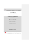
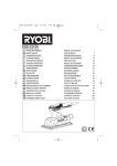
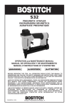
Table of Contents
Safety Information ........................................................................................................................... 3
Reference Manuals ......................................................................................................................... 5
Recommended Spare Parts List ...................................................................................................... 5
Software Solutions .......................................................................................................................... 5
M9000 Cutting System Familiarization ............................................................................................ 6
Computer Control Assembly ............................................................................................................ 7
Festoon Kit & Cable Assembly ...................................................................................................... 8
Gantry Assembly .......................................................................................................................... 10
Front Cover Assembly ................................................................................................................... 11
Back Cover Assembly ................................................................................................................... 12
Control Panel Assembly ................................................................................................................ 13
Front End Plate Assembly ............................................................................................................ 14
Back End Plate Assembly ............................................................................................................ 16
Main Tube Assembly ..................................................................................................................... 18
Y-Carriage Assembly ..................................................................................................................... 20
Tool Head Assembly H9900-3A ..................................................................................................... 22
Rack & Rail Assembly .................................................................................................................. 24
Static Table Assembly ................................................................................................................... 26
Vacuum Components .................................................................................................................... 28
E-Box Assembly 31-B4001 ........................................................................................................... 30
Optional: Heavy Duty Tool Head Assembly, 1" H9299-1HD ............................................................ 32
Optional: Fiber Tool Head Assembly H9299-2FC ........................................................................... 34
Optional: Static Table Diagnostic Control Cabnet 31-S3285 (110v) 31-S3285-1 (220v/1ph) ............ 36
Bottom Panel Assembly 68-26105-1 ............................................................................................. 37
Rear Panel Assembly, Static 68-26096-1 (110v) 68-26096-4 (220v/1ph) .......................................... 38
Static Gantry E-Plate Assembly 68-26094 ..................................................................................... 40
Easi Pull Assembly 67-26091-MS ................................................................................................. 42
Technical Data .............................................................................................................................. 44
IMPORTANT
The purchaser must instruct all operators on the proper use of the equipment.
All standard industrial safety measures and equipment should be provided to
protect the operator. Operators must be cautioned that improper or careless
use of this equipment may cause personal injury. If you do not have qualified
operators to instruct new persons, contact your Eastman sales representative
or Eastman factory direct.
Disconnect electrical power source from before proceeding with any installation, adjustment or repair of the M9000 Automated Cutting System.
2
Form E-509-M9000
Safety Information
Throughout this manual, safety information is presented by the use of the terms WARNING, CAUTION, and NOTE. These terms have the following meanings:
WARNING
A warning contains critical information regarding potential safety hazards that can occur
during proper use or misuse of the machine. Failure to follow these procedures may result
in serious personal injury to the user.
CAUTION
A caution contains instructions for the use or maintenance of the machine. Failure to follow
these procedures may result in damage to the machine.
ELECTRICAL HAZARD
An electrical hazard calls attention to a procedure, practice, or the like, which, if not correctly performed or adhered to, could result in personal injury. Do not proceed beyond an Electrical Hazard.
Supplementary information may be given in a Note.
Safety and Indemnification
During the life of the machine, the purchaser agrees to provide to all machine users (including its own employees and independent contractors) all relevant safety information, including warning labels and instruction manuals. The purchaser also agrees to maintain the
safety features and working condition of the machine, and to adequately train all users in
the safe use and maintenance of the machine. The purchaser agrees to defend, protect,
indemnify, and hold Eastman Machine Company and its subsidiaries harmless from and
against all claims, losses, expenses, damages, and liabilities to the extent that they have
been caused by the purchaser’s failure to comply with the terms and instructions of this
manual.
General Safety Precautions
WARNING
This machine is equipped with very sharp and dangerous tools. Keep hands, arms, and
hair away from the cutting area and drive system at all times. Safety gloves, glasses, and
appropriate clothing may prevent serious personal injuries.
Disconnect all power sources to the machine when it is not in use or during routine maintenance, including cleaning and lubrication.
The purchaser must instruct all operators in the proper use of the machine according to the
instructions in this manual. This training must include instruction on the potential safety
hazards arising from the use or misuse of the machine. In addition to such training, the
purchaser should provide written work instructions as necessary to ensure correct use of
the machine for specific cutting applications.
Form E-509-M9000
3
WARNING
The purchaser must provide appropriate safety measures and equipment as recommended
in this manual. Observe all statutory requirements concerning the use of hazardous machinery that apply to your location.
Do not modify this machine or disable safety features. Unauthorized modification may result in serious personal injuries to the user. A qualified electrician, familiar with applicable
codes and regulations, must make electrical connections to this machine. Misuse of this
machine or use of this machine as part of another machine may result in serious personal
injuries to the user.
Safety labels must be kept clean and legible at all times. Call the Eastman factory to order
replacement labels.
CAUTION
Eastman Technology Systems equipment is not designed for use in conditions of extreme
temperature or humidity. Operating this equipment in an environment outside the specified
ranges may result in damage and will void the warranty.
Acceptable operating temperature range:
10ºC to 35ºC (50º to 95ºF).
Acceptable operating humidity range:20% to 80% (non-condensing).
Altitude: We anticipate that the system will operate within all specifications at an altitude up
to 1000m above mean sea level.
Transportation:
During transportation and storage, the system is capable of withstanding ranges from -25oC to 55oC and for periods not exceeding 24 hrs. at
up to +70oC.
Lifting/Moving: The lifting or moving of this system must be in accordance with the installation requirements. Failure to adhere to these installation requirements may
cause injury to persons or hinderance or the machine performance.
This system operates at 96dba under full load. Hearing protection devices must be used
during prolonged exposure to the noise.
Specifications
Computer
E-Box, Conveyor
E-box, Gantry
Internal Blower (5)
External Blower (1)
Gantry
4
Form E-509-M9000
Voltage
120vac
230 vac
120vac
230vac
230vac
120vac
5/12vdc
Current
6A
30A
10A
17.4A Each
60A
1.2A
3/2A
Frequency
50/60 Hz
50/60 Hz
50/60 Hz
50/60 Hz
50/60 Hz
50/60 Hz
50/60 Hz
# of phases
Single
Three
Single
Three
Three
Single
Single
The Eastman ETS-M9000 Automated Cutting machine has been inspected and tested at the factory prior to
shipment. The ETS-M9000 machine is shipped partially disassembled and requires some assembly and setup
before operation can take place. Refer to the installation guide for installation instructions. To get the best performance, familiarize yourself and all operators with all functions and adjustments of this equipment. Refer to the
M9000 service manual. Before any operation takes place it is important carefully read and follow the instructions in
these reference manuals.
This Illustrated Parts List is a comprehensive list of the components used in the machine. When ordering replacement parts, please include machine name and serial number. Some machine configuration may require additional
components not shown, please consult factory for part numbers.
The following list of recommended spare parts and reference manuals may be included with your machine or
purchased at a later date.
Reference Manuals
E-509 .................................. M9000 Instruction and Service Manual
E-509-M9000 ...................... M9000 Illustrated Parts List
E-515 .................................. Automated Cutting Tools Illustrated Parts Manual
E-519 .................................. Cutting Surface Selection Chart
E-521-2.1 ............................ Easicut 2 Software Manual
E-522 .................................. Air Brush Marking System Manual
Recommended Spare Parts List
Part Number
Description
10-00900-2 .......................... Computer Multifunction Board
31-03002 ............................. Motion Control Board, MEI
31-B2005 ............................ X-Axis Motor
31-S3205-1 ......................... Y-Axis Motor
31-03012-2 .......................... Motor Amplifiers, Quantity of 2
54-26295 ............................. X-Axis Spur Gear, Quantity of 2
31-12660-1 .......................... 5 & 12 vdc Power Supply
54-D0066 ............................ X-Axis Motor Pulley
67-12983 ............................. X-Axis Linear Bearing, Quantity of 2
Consult Factory .................. Replacement Cutting Surface Kit
See E-515 Manual .............. Replacement Pen
See E-515 Manual .............. Replacement Cutting Tools
Software Solutions
Eastman offers a wide variety of software to solve even the most difficult tasks.
Please consult your nearest Eastman Representative or the Eastman Factory direct for more information.
Form E-509-M9000
5
M9000 Cutting System
Familiarization
6
Form E-509-M9000
Computer Control
Assembly
Software Solutions
Eastman offers a wide variety of software to solve
even the most difficult tasks. Please consult your
nearest Eastman Representative or the Eastman
Factory direct for more information.
ITEM PART No.
1*
67-26309
67-26309-1
54-26422
31-S3285
2
10-26005
*
10-26003
3
11-00868-02
4
11-00054-1
*
11-00054
5 Consult Factory
10-00900-2
31-S1009
31-03002
6
31-B4001
DESCRIPTION
Control Console
Control Console, Pressurized
Computer Desk w/Casters
Diagnostic/E-box Cabinet
15" Color Monitor
17" Color Monitor
Computer Keyboard
Computer Mouse, Unshielded
Computer Mouse, Shielded
Computer (10-26002)
Multifunction Board
MEI to Multifunction Cable
Motion Control Board, MEI
E-Box Assembly
QTY
1
1
1
1
1
1
1
1
1
1
1
1
1
1
* Optional
Form E-509-M9000
7
Festoon Kit &
Cable Assembly
Note: Table length 72 feet and longer require double
Festoon Track and Trolley.
Remote E-Stop Kit (not shown)
31-S3003-1
Kit for 12'-36' Long Table
31-S3003-2
Kit for 48'-72' Long Table
31-S3003-3
Kit for 84'-108' Long Table
8
Form E-509-M9000
ITEM PART No.
1
67-26056
2
67-26043
67-26044
3
67-26055
4
67-26040
5
67-26038
67-26038-4
67-26038-8
6
67-26041
7
67-26042
8
373-99-12
9
31-26040
10
31-26039
11
27-02996-1
12
100-13-2
13
100-19-9
14
373-99-12
15
100-18-2
16
96-26009-TL
17
54-26689
18
E-134
19
TL-261
20
335-38-20
21
410-38
22
54-27024
23
368-14-16
A/R- As Required
TL - Table Length
DESCRIPTION
Festoon Trolley, 4 Wheel
Festoon Trolley, Nylon, 2 Wheel
Festoon Trolley, Steel, 2 Wheel
Webbing Strap, Cable Tie
Festoon Mounting Track
Festoon Roller Track, 144"Long
Festoon Roller Track, 48"Long
Festoon Roller Track, 96"Long
Festoon Track Splice
Festoon End Stop
Screw, Self Drill & Tap Type
End Cap Set, Cable Protector
Cable Protector, Floor
1/4" Air Line
Swivel Elbow, 1/4"
Filter Mounting Bracket
Screw, Self Drill & Tap Type
Filter Regulator
Festoon Rail & Trolley Kit
Rail Mount, Double Festoon Style
Wire Rope Strain Relief
Clamp, Wire Rope
Screw, Socket Hd. 3/8-16 x 1-1/4
Washer, Flat 3/8
Mounting Plate, Stop
Screw, Self Tap #14 x 1"
QTY
1
A/R
A/R
A/R
A/R
A/R
A/R
A/R
A/R
1
A/R
1
2
A/R
2
1
2
1
1
A/R
1
2
4
4
2
4
Table length 72 feet and longer require
double Festoon Track and Trolley System
EasiPull Note:
K9000S-TL
Part No.
31-B1013-CL
31-B1016-CL
31-B1019-CL
31-B1022-CL
31-S1005-CL
31-S1020-CL
*31-S1023-CL
X-Axis Cable Assembly Kit
Description
Main AC Power Cable
Hall Effect Cable
Y & Z Motor Cable
X1-X2 Motor Cable
UIT Cable
Encoder Cable
I/O Cable
Emergency Stop Box Assembly
31-S3003-1
Kit for 12'-36' Long Table
31-S3003-2
Kit for 48'-72' Long Table
31-S3003-3
Kit for 84'-108' Long Table
CL - Cable Length
* EasiPull Note only: Move Male Pin 26 to 27.
Part No.
31-B1021-10
31-S3309
31-B1013-25
Form E-509-M9000
Additional Cables
Description
Amp I/O Cable, 10 Ft. Long (E-box Only)
Amp I/O Cable, 3 Ft. Long (Diagnostic Cabinet Only)
AC Power Cable, E-Box 25 Ft. Long (E-box Only)
9
Gantry Assembly
G9000MS
Note: MS- Machine Size
ITEM
1
2
3
4
5
6
7
8
10
Form E-509-M9000
PART No.
409-99
333-93-8S
335-93-8
410-080
335-93-10
410-010
402-010
335-102-10
DESCRIPTION
Finish Washer
Screw, Cover
Screw, Socket #8-32 x 1/2
Washer, Flat #8
Screw, Socket #8-32 x 5/8
Washer, Flat #10
Washer, Lock #10
Screw, Socket #10-32 x 5/8
QTY
A/R
A/R
4
12
12
6
6
6
Front Cover Assembly
54-03004-2
Form E-509-M9000
ITEM
1
2
3
4
5
6
7
8
9
10
11
12
13
14
15
16
17
18
19
20
PART No.
333-34-12Z
54-26419
54-26420
333-102-8S
54-26423
91-26002
91-00554
91-26005
54-C0338-2
67-26311
54-26421
318-86-6
404-080
54-26426
11-1193
404-040
313-81-8
54-26422
9078-003
205-38
DESCRIPTION
QTY
Screw, Button Hd. 1/4-20 x 3/4 2
Stop Disk
2
Rod, Stop Disk
1
Screw, Button Hd. 10-32 x 1/2 6
End Cap
2
Decal, Small Eastman
1
Decal, M9000
1
Decal, Logo
1
Operator Side Cover
1
Slide Bearing
2
Bearing Mount
1
Screw, Pan Head #8-32 x 3/8 2
Lock Washer, #8 Internal
2
Switch Bracket
1
limit Switch
1
Lock Washer, #4 External
2
Screw, Round Hd. #4-40 x 1/2 2
Bearing & Switch Mount
1
Sping Plunger, 3/8-16
1
Hex Nut, 3/8-16
1
11
Back Cover Assembly
31-S3005-2
ITEM
1
2
3
4
5
6
7
8
9
10
11
12
PART No.
333-34-12Z
54-26419
54-26420
333-102-8S
54-26423
54-C0339-2
67-26311
54-26421
318-86-6
404-080
54-26426
DESCRIPTION
QTY
Screw, Button Hd. 1/4-20 x 3/4 2
Stop Disk
2
Rod, Stop Disk
1
Screw, Button Hd. 10-32 x 1/2 6
End Cap
2
Non-Operator Side Cover
1
Slide Bearing
2
Bearing Mount
1
Screw, Pan Head #8-32 x 3/8 2
Lock Washer, #8 Internal
2
Switch Bracket
1
Form E-509-M9000
ITEM
12
13
14
15
16
17
18
19
PART No.
11-1193
404-040
313-81-8
54-26422
9078-003
205-38
91-26002
91-00554
DESCRIPTION
QTY
limit Switch
1
Lock Washer, #4 External
2
Screw, Round Hd. #4-40 x 1/2 2
Bearing & Switch Mount
1
Sping Plunger, 3/8-16
1
Hex Nut, 3/8-16
1
Decal, Small Eastman
1
Decal, M9000
1
ITEM PART No.
20
31-12943
31-00831
31-00832
91-26011
21
91-00558
22
31-00834
23
31-12628
31-00831
24
91-26006
DESCRIPTION
QTY
Mushroom Switch, Red
1
Switch Contact, NO
1
Switch Contact, NC
1
Decal, Yellow Emergency Stop 1
Decal, Emergency, Off
1
Light,12v Red
2
Pause Switch, Yellow
1
Switch Contact, NO
1
Decal, Pause
1
Control Panel Assembly
31-S9003
ITEM PART No.
1
31-26035
79-00417
2
333-93-8
3
31-00828
4
31-00831
31-00830
5
31-00839
6
31-12943
7
31-00831
8
31-00832
9
31-00834
10
31-12628
11
31-00831
12
31-00834
13
333-93-8
14
54-C0335-2
15
31-00838
DESCRIPTION
QTY
Control Panel Assembly
1
Key Pad Label
1
Screw, Button Hd #8-32 x 1/2 4
Selector Switch
1
Switch Contact, NO
1
Base
1
Indicator Light, 125VAC Green 1
Stop Button, Mushroom
1
Switch Contact, NO
1
Switch Contact, NC
1
Indicator Light, Red
1
Switch, Yellow Push
1
Switch Contact, NO
1
Indicator Light, Red
1
Screw, Button Hd #8-32 x 1/2 4
Plate, Control Panel
1
Indicator Light, 12V Green
1
Form E-509-M9000
ITEM
16
17
18
19
20
21
22
23
24
25
PART No.
31-00828
31-00831
31-12947
31-00991
54-C0334
203-86
402-060
4C2-111
91-26011
31-00830
DESCRIPTION
Selector Switch
Switch Contact, NO
Joy Stick
Switch, Lever Style
Panel Support
Hex Nut, #6-32
Lock Washer
Arched Speed Nut
Decal, Emergency Stop
Switch Base
QTY
1
1
1
2
2
14
14
4
1
5
13
Front End Plate Assembly
68-03002
14
Form E-509-M9000
ITEM
*1
2
3
4
5
6
7
8
9
*9A
10
11
12
13
14
15
16
17
18
19
20
21
22
23
24
25
26
27
28
29
30
31
PART No.
31-S9003
333-86-4
31-03101
67-01053
67-01051-1
342-93-4
54-D0066
**
54-26019
31-B2005
335-93-8
54-LC095
67-12984
54-D0019
9063-104
54-D0276
9063-010
54-26295
342-102-5
335-35-24
54-LC098
67-12983
54-LC097
-341-4-12
335-93-8
335-93-8
54-C0306
11-1940
31-26012-15
11-1981
31-26012-16
DESCRIPTION
QTY
Control Panel Assembly
1
Screw, Button Hd. #6-32 x 1/4 2
Ground Terminal
1
Collar, Stop
1
Shock Absorber
1
Setscrew, #8-32 x 1/4
2
Motor Pulley
1
Key, part of motor assembly
1
Motor Mounting Plate
1
X1-Axis Motor with Harness
1
Screw, Socket Hd. #8-32 x 1/2 4
Bearing Spacer Shim
1
Bearing
2
Bearing Housing
2
Key, .188 x .188 x .859
1
Drive Shaft
1
Key, .188 x .188 x .734
1
Spur Gear
1
Setscrew #10-32 x 5/16
2
Screw, Socket 1/4-28 x 1 1/2 2
Backlash Adjuster
2
Linear Bearing
2
Rail Car Connector
2
-Screw, Socket m4 x 12mm
8
Screw, Socket Hd. #8-32 x 1/2 6
Screw, Socket Hd. #8-32 x 1/2 18
Cover Mounts
9
Spacer, 7/16 Long
4
Power Supply, 5vdc
1
Spacer, 1-1/8 Long
8
Power Supply, 12vdc
1
Form E-509-M9000
ITEM PART No.
32
54-26025
33
404-060
333-86-6
31
31-26012-16
32
404-060
33
313-86-32
34
54-D0485
35
54-D0022-2
36
335-93-8
37
67-D0216-5
38
332-102-10
39
67-02963-1
40
54-D0065
41
342-93-4
42
335-102-10
43
402-010
44
410-010
45
335-102-10
46
332-102-20
47
410-34
48
402-34
49
335- 34-20
333-34-20
*50 31-00922
51
54-C0300
52
206-44
*53 335-93-4
*54 54-26224
55
333-86-8
DESCRIPTION
QTY
Power Supply Shield
1
Star Lock Washer
4
Screw, Socket Hd. #6-32 x 3/8 4
Power Supply, 12v
1
Star Lock Washer
4
Screw, Round Head #6-32 x 2 4
Drive Standoff Plate
2
Shaft Support
1
Screw, Socket Hd. #8-32 x 1/2 6
Snap Ring
4
Screw, Flat Hd. #10-32 x 5/8
8
Drive Belt,htd
1
Pulley, Large
1
Setscrew, #8-32 x 1/4
2
Screw, Flat Hd. #10-32 x 5/8
8
Lock Washer #10
8
Flat Washer #10
8
Screw, Socket #10-32 x 5/8
8
Screw, Flat Hd. #10-32 x 1 1/4 8
Flat Washer, 1/4
2
Lock Washer, 1/4
4
Screw,Socket 1/4-20 x 1 1/4
2
Screw, Button 1/4-20 x 1 1/4
2
Roller Switch, 90 degree spdt 2
Operator Side Plate, Right
1
Nut, Hex Jam 1/2-20
2
Screw, Socket #8-32 x 1/4
4
E-chain Funnel
2
Screw, Socket Hd. #6-32 x 1/2 4
* Not included in assembly
** Required for table length 72 ' and higher
A/R -As Required
15
Back End Plate Assembly
68-03001
16
Form E-509-M9000
ITEM
1
2
3
4
5
6
7
8
9
10
11
12
13
14
15
16
17
18
19
20
21
22
23
24
25
26
27
28
29
30
31
32
33
34
35
36
37
PART No.
**
54-26019
31-B2000
342-93-4
54-D0066
333-86-4
67-01051-1
67-01053
100-13-2
27-20001
203-93
404-080
335-93-8
54-C0301
54-C0306
335-93-8
11-919
333-86-4
31-00922
410-34
402-34
335-34-20
333-34-20
67-D0216-5
54-D0065
67-02963-1
54-D0485
332-102-10
54-D0022-2
67-12984
54-D0019
10-00903-2
305C8-1
54-C0342-1
67-01005
333-86-4
100-17-1
31-02693-2
31-00976
31-02973
31-12929
31-12930
DESCRIPTION
QTY
Key, part of motor assembly
1
Motor Mounting Plate
1
X2-Axis Motor with Harness
1
Setscrew, #8-32 x 1/4
2
Motor Pulley
1
Screw, Button Hd. #6-32 x 1/4 2
Shock Absorber
1
Collar, Shock Absorber
1
Elbow 1/4 NPT x 1/4"
2
Air Control Regulator
1
Hex Nut, #8-32
4
Lock Washer, #8
4
Screw, Socket Hd. #8-32 x 1/2 18
Side Plate, Left
1
Cover Mounts
9
Screw, Socket Hd. #8-32 x 1/2 6
Ground Terminal
1
Screw, Button Hd. #6-32 x 1/4 2
Roller Switch, 90 degree spdt 2
Flat Washer, 1/4
2
Lock Washer, 1/4
4
Screw, Socket 1/4-20 x 1 1/4 2
Screw, Button 1/4-20 x 1 1/4
2
Snap Ring
4
Pulley, Large
1
Drive Belt,htd
1
Drive Standoff Plate
2
Screw, Flat Hd. #10-32 x 5/8
8
Shaft Support
1
Bearing
2
Bearing Housing
2
X-Axis Board
1
Screw, Pan Hd. #4-40 x 1/4
4
Electrical Pan
1
Locking Screw Kit
1
Screw, Button Hd. #6-32 x 1/4 12
1/4" Fitting
1
3-Pin Circular Connector (only) 1
8-Pin Connector, Small (only) 1
Strain Relief
1
10mm Boot
1
12mm Boot
1
Wide Gantry Machines Only
Double Bearing Kit 96-26066
Form E-509-M9000
ITEM
38
39
40
41
42
43
44
45
46
47
48
49
50
51
52
53
54
55
56
57
58
59
60
61
62
63
64
65
66
67
68
69
70
71
72
73
74
75
76
77
78
PART No.
31-S1010-MS
67-01005
67-01005
31-00972
31-02973
31-12929
31-12930
335-93-8
54-C0318
54-C0435
342-93-4
332-102-20
335-102-10
402-010
335-102-10
410-010
410-080
402-080
335-93-8
335-93-10
335-93-8
341-4-12
31-S9005
54-LC097
67-12983
54-LC098
335-35-24
54-LC095
54-D0276
9063-104
9063-010
54-26295
342-102-5
100-14-1
333-102-8
410-060
206-44
335-34-20
54-C0320-1
54-26299-1
54-26299-2
65-26024
335-93-8
100-18-21
100-13-2
A/R -As Required
-MS Machine Size
* - not Included
A
27-02996-1
DESCRIPTION
QTY
UIT Cable
1
Locking Screw Kit (part of)
1
Locking Screw Kit (part of)
1
8-Pin Connector, Large (only) 1
Strain Relief
1
10mm Boot
1
12mm Boot
1
Screw, Socket Hd. #8-32 x 1/2 4
E-Chain Mount
1
E-Chain Side Mount
2
Setscrew, #8-32 x 1/4
2
Screw, Flat Hd. #10-32 x 1 1/4 8
Screw, Socket #10-32 x 5/8
8
Lock Washer #10
8
Screw, Socket #10-32 x 5/8
8
Flat Washer #10
8
Flat Washer #8
4
Lock Washer #8
4
Screw, Socket Hd. #8-32 x 1/2 4
Screw, Socket Hd. #8-32 x 5/8 4
Screw, Socket Hd. #8-32 x 1/2 6
Screw, Socket m4 x 12mm
8
Pressure Regulator Assembly 1
Rail Car Connector
2
Linear Bearing
2
Backlash Adjuster
2
Screw, Socket 1/4-28 x 1 1/2 2
Bearing Spacer Shim
1
Drive Shaft
1
Key, .188 x .188 x .859
1
Key, .188 x .188 x .734
1
Spur Gear
1
Setscrew #10-32 x 5/16
4
Tee Fitting, 1/4"
1
Screw, Button Hd #10-32 x 1/2 4
Flat Washer, #6
4
Nut, Hex Jam 1/2-20
1
Screw, Socket 1/4-20 x 1 1/4 2
Cable Clamp
1
Pull Bracket, Festoon
*1
Pull Bracket, DoubleTrack only *1
Vibration Dampener
4
Screw, Socket Hd. #8-32 x 1/2 2
Valve, Easi Pull
1
Elbow 1/4 NPT x 1/4"
2
Air Tubing, 1/4" (not shown)
A/R
17
Main Tube Assembly
18
Form E-509-M9000
ITEM
1
2
3
4
5
6
7
8
9
10
11
12
13
14
15
16
17
18
19
20
21
22
23
24
25
PART No.
333-93-8S
409-99
54-C0340-MS
54-26133-MS
91-26003
67-C0219-MS
67-C0220
67-12990-1
31-00921
211-86
54-C0411-MS
335-102-6
410-010
54-C0302-MS
54-C0305-1
54-C0305-2
211-86
70-26001
67-02634
211-102
67-26177
67-26111
67-26178
211-34
---
DESCRIPTION
QTY
Screw, Button Hd. #8-32 x 1/2 A/R
Finish Washer
A/R
E-Chain Cover
1
Tube Cover (Larger Machines only) 1
Decal, Eastman 4" Medium
2
Linear Rail
2
Linear Rail Mount
A/R
Gear Rack, 96" 20p
A/R
Roller Switch
3
Stop Nut, #6-32
6
Rack Support
1
Screw, Socket Hd. 10-32 x 3/8 12
Flat Washer, #10
12
Main Tube
1
Insert, Short
2
Insert, Long
2
Stop Nut, #6-32
A/R
Duct, 1 x 1.5
A/R
Duct Cover, 1"
A/R
Stop Nut, #10-32
A/R
E-Chain Mounting Set
1
E-Chain (Sold by the Foot)
A/R
E-Chain Cable Separators
A/R
Stop Nut, 1/4-20
2
ITEM
26
27
28
29
30
PART No.
70-26005
211-102
70-26006
54-C0410-MS
333-102-6
31
32
-333-34-8
33
333-102-4
34
335-86-12
35
36
402-060
333-102-6
37
38
39
40
333-86-16
333-86-16
410-060
67-26081
DESCRIPTION
Duct, 2" Wide
Stop Nut, #10-32
Duct Cover, 2"
Belly Pan
Screw, Button Hd.
#10-32 x 3/8
QTY
A/R
A/R
A/R
1
A/R
Screw, Button Hd.
#1/4-20 x 1/2
Screw, Button Hd.
#10-32 x 1/4
Screw, Socket Hd.
#6-32 x 3/4
Lock Washer, #6
Screw, Button Hd.
#10-32 x 3/8
Screw, Button Hd. #6-32 x 1
Screw, Button Hd. #6-32 x 1
Flat Washer, #6
Duct Cover, 2.5
A/R
A/R
6
6
A/R
A/R
2
A/R
A/R
A/R
A/R -As Required
MS - Machine Size
A
27-02996-1
Air Tubing, 1/4" (not shown)
B
27-02996-2
Air Tubing, 5/32" (not shown) A/R
Main Tube Cable Kit (96-26074-ms) Not Shown
Y-Cable Kit (31-S3207-ms) Not Shown
31-S3204-MS
31-S3206-MS
Multi-Tool Y-Axis Cable
Y/Z Power Cable
Form E-509-M9000
31-S1010-MS
31-S3006-MS
31-S3341-MS
31-S3002-MSXH
31-S3002-MSYH
31-S3002-MSYL
31-S3009-MS
31-S3010-MS
UIT Touch Screen Cable
Dual 5&12 Power Supply Cable
AC Power Harness
Gantry Switch X1-Home Cable
Gantry Switch Y-Home Cable
Gantry Switch Y-Limit Cable
Tool Control Cable
E-Off/Pause Cable
19
Y-Carriage Assembly
68-03005
20
Form E-509-M9000
ITEM
1
2
3
4
5
6
7
8
9
10
11
12
13
14
15
16
17
18
19
*20
21
22
23
PART No.
335-93-8
342-86-4
54-H0232
67-00520
67-D0216-1
54-12985
342-102-5
54-H0233
54-D0267
67-9063-003
54-02934-3
342-86-4
67-D0215
54-H0235
335-93-8
54-H0231
54-H0236
54-H0236-1
335-93-8
67-06818
31-S3205-1
335-93-12
402-080
342-93-3
DESCRIPTION
QTY
Screw, Socket Hd. #8-32 x 1/2 4
Setscrew, #6-32 x 1/4
2
Y-Car Backlash Plate
2
Bearing, Y-Car Pulley
2
Snap Ring, 3/8
3
Large Y-Car Pulley, 72T
1
Setscrew, #10-32 x 5/16
2
Backlash Cross Plate
1
Y-Car Drive Shaft
1
1/8" Square Key
1
Small Y-Car Pulley, 25T
1
Setscrew, #6-32 x 1/4
2
Y-Car Drive Belt, 113T
1
Y-Car Left Side Plate
1
Screw, Socket Hd. #8-32 x 1/2 44
Y-Car Horiz. Plate, 2nd
1
Y-Car Main Vertical Plate
1
Y-Car Plate, Foam Cutter only 1
Screw, Socket Hd. #8-32 x 1/2 2
Y-Car Bearing Assembly
4
Y-Car Motor w/Connector
1
Screw, Socket Hd. #8-32 x 3/4 4
Lock Washer, #8
4
Setscrew, #8-32 x 3/16
2
ITEM
24
25
26
27
28
29
30
31
32
*33
34
35
36
37
*38
39
40
41
42
43
PART No.
54-D0214
54-H0234
54-H0341
54-H0230
332-86-8
211-93
335-102-8
27-H0410
333-34-6
67-26177
10-00904-2
404-060
333-86-8
27-02996-1
68-26011
68-26011-1
68-03009
68-03009-2
100-13-3
100-13-7
27-H0409
100-11-2
27-H0382
27-H0382-2
44
45
46
410-010
335-102-10
31-26461
DESCRIPTION
QTY
Y-Car Motor Pulley, 15T
1
Y-Car Right Side Plate
1
Home Plate
1
Y-Car Main Plate
1
Screw, Flat Hd. #6-32 x 1/2
2
Lock Nut, #8-32
4
Screw, Socket Hd. 10-32 x 1/2 16
1/4 NPT Plug
2
Screw, Button Hd. 1/4-20 x 3/8 2
E-Chain End Bracket
1
Y-Axis Board
1
Lock Washer, #6
4
Screw, Button Hd. #6-32 x 1/2 4
Spacer Tubing (sold by foot) A/R
Solenoid Ass'y, 3 Station, 12v 1
Solenoid Ass'y, 4 Station, 12v 1
Solenoid Ass'y, 5 Station, 12v 1
Solenoid Ass'y, 6 Station, 12v 1
5/32" Swivel Elbow
7
1/4" Swivel Elbow
1
1/8 NPT Plug
1
1/4" Fitting
1
5 Station Solenoid Block
(without Electrical Connector) 1
1 Station Replacement Solenoid
(without Electrical Connector) 1
Lock Washer, #10
2
Screw, Socket Hd, #10-32 x 5/8 2
Grounding Wire
1
* Not included in assembly
A/R -As Required
Form E-509-M9000
A
27-02996-1
Air Tubing, 1/4"
A/R
B
27-02996-2
Air Tubing, 5/32"
A/R
21
Tool Head Assembly
H9900-3A
Refer to
Automated Cutting Tools Manual
E-515 for latest Available Tools
Pen Assembly
* Sharpie Adapter Kit #96-26050
22
Form E-509-M9000
ITEM PART No.
1
100-13-3
2
67-26092-2
54-26152
3
67-26190
4
335-34-8
5
54-26229
6
54-26232
7
335-102-10
8
54-26234
9
31-S3205-1
10
335-93-14
11
402-080
12
67-26188
13
345-93-4
14
67-12972-1
15
67-26054
16
211-93
17
67-26191
18
332-102-6
19
81-00002
20
333-93-8
21
54-H0403
22
67-26184
23
54-26230
24
65-26009
25
54-12971
26
402-010
27
335-102-8
28
67-26185
29
54-26231
30
67-26186
31
54-26021-1
32
65-26016
33
335-86-16
34
54-H0213
35
68-26027
36
54-26272
37
333-3-6
38
402-040
DESCRIPTION
QTY
Swivel Elbow, 1/8 npt x 5/32
6
Air Cylinder
3
Jam Nut, 5/8-18
3
Cylinder Mounting Bracket
1
Screw, Socket Hd. 1/4-20 x 1/2 4
Bumper
3
Cylinder Coupling, Non-Rotating 3
Screw, Socket Hd. #10-32 x 5/8 3
Shaft & Bearing Assembly
3
Z-Motor, Servo w/Connector
1
Screw, Socket Hd. #8-32 x 7/8 4
Washer, Lock #8
4
Motor Mounting Plate
1
Setscrew, #8-32 x 1/4
2
Belt, 115t x 3 mm
1
Pulley, 22t x 3mm
1
Stop Nut, #8-32
4
H9900-3A Tool Head Frame
1
Screw Flat Hd. 10-32 x 3/8
4
Laser Pointer
1
Screw, Button Hd. #8-32 x 1/2 2
Mount, Laser Pointer
1
Bearing, 16mm ID
3
Spacer
3
Setscrew, #6-32 x 1/4
6
Pulley, 44t x 3mm
3
Washer, Lock #10
3
Screw, Socket Hd.#10-32 x 1/2 1
Cushion Ring
3
Bearing Adapter
3
Bearing 20mm ID
3
Tool Adaptor
3
Setscrew, #8-32 X 7/64
6
Screw, Socket Hd. #6-32 x 1 2
Pen Holder
1
Pen Assembly
1
Pen Mounting Bracket
1
Screw, Button Hd. 3m x 6m
4
Washer, Lock #4
2
ITEM
39
40
41
42
43
44
45
46
47
48
49
50
51
52
53
54
55
56
57
58
59
60
61
62
63
64
65
66
67
68
69
91-26002-W
*70 67-26163
*71 67-26174
*72 67-26175
*73 67-26176
74
67-26359
75
670-211
* Not Shown
A/R - As Required
B
Replacement Ink Pens
Part No.
Description
67-26152
Black Ink pen
67-26152-1 Yellow Ink Pen
67-26152-2
Silver Ink Pen
67-26152-3
Ultraviolet Ink Pen
67-26152-4
Gold Ink Pen
67-26152-5
Green Ink Pen
67-26152-6
Black Bold Ink Pen
Form E-509-M9000
Qty
1
1
1
1
1
1
1
PART No.
54-26269
67-03004
355-2-2
54-26270
67-26224
67-26223
335-86-4
54-26301-1
333-86-4
54-26273
67-26224
100-18-19
31-26183
333-102-6
410-010
31-26183
31-03008-1
67-26151
Optional
67-26151
203-84
67-26187
409-99
333-102-8S
67-26182
54-26393
68-26045
27-02996-2
DESCRIPTION
QTY
Slide Lock
1
O-Ring
1
Shoulder Bolt, 1/8 x 1/8
1
Cylindar End
1
Cylindar Nut
2
Pen Mount Slide Bearing
1
Screw, Socket Hd. #6-32 x 1/4 2
Pen Mounting Plate
1
Screw, Button Hd. #6-32 x 1/4 2
Cylindar Mounting Bracket
1
Pen Cylinder
1
Flow Control Fitting
2
Washer & Nut, (Part of #57)
1
Screw, Button Hd. 10-32 x 3/8 6
Washer, Flat #10
6
Prox Switch
1
Cable, Prox Switch
1
Pen Holder/Adapter
1
See Chart
1
Pen Holder/Adapter(Part of #59) 1
Nut, Hex #5-40
1
Cover
1
Finish Washer, #10
4
Screw, Button Hd. #10-32 x 1/2 4
Tool Guard
1
Shoulder Bolt
6
Pen Lift Assembly, Double Acting
(Pen Not Included)
1
Decal, Eastman Logo
1
Ball Driver. 9/64", 7" Long
1
T-Handle, 9/64", 6" Long
1
Hex Key, 5/64"
1
Hex Key, 2.5 mm
1
Back Cover, Optional
1
Pen/Marker Locking O'ring
1
Air Tubing, 5/32"
A/R
Replacement Ink Markers
Part No.
Description
Qty
67-26286-2
Metalic Silver Marker
1
67-26286-4
Metalic Gold Marker
1
67-26339
Fine Black Marker
1
67-26339-5
Fine Red Marker
1
67-26340-6
Fine White Marker
1
Markers Require Adapter Kit #96-26050
23
Rack & Rail Assembly
Off Operator Side
Operator Side
Note: ** Components sold in matched sets. Please
consult factory before placing your order.
Rack & Rail Mounting Dimensions
24
Form E-509-M9000
Rack & Rail Assembly
(Off Operator Side)
ITEM
1
2
3
4
5
6
7
8
9
10**
11**
12
13
14
15
16**
17
18**
19**
20
21
22
23
PART No.
333-93-6
54-26077
54-T0412
332-102-14
54-T0413
67-01051-2
54-T0179-5
333-34-48
333-34-6
54-T0013-2
54-T0013-3
54-T0013-1
54-T0012-7
603-8-8-14
321-34-32
333-102-8
410-010
54-T0012-2
54-T0012-1
341-3-16
67-12979-1
54-26018
54-00236-1
54-00236-2
54-00236-3
54-00236-4
410-34
402-34
203-34
54-26077-2
DESCRIPTION
QTY
Screw, Button Hd. #8-32 x 3/8
4
Stop Cam, Side Activation
*2
Stop Cam, Long, Top Activation *1
Screw, Flat Hd. #10-32 x 7/8
*4
Stop Cam, Short, Top Activation *1
Shock Absorber
2
Shock Mount
4
Screw, Button Hd. 1/4-20 x 3" 8
Screw, Button Hd. 1/4-20 x 3/8 A/R
Dust Cover, 8'
A/R
Dust Cover, 6'
A/R
Dust Cover, 4'
A/R
Rack Plate, 6'
A/R
Key, Square, 1/4 x 1/4 x 7/8
A/R
Screw, Flat Hd. 1/4-20 x 2"
A/R
Screw, Button Hd.,#10-32 x 1/2 A/R
Washer, Flat #10
A/R
Rack Plate, 4'
1
Rack Plate, 8'
1
Screw, Socket Hd. M3 x 16
A/R
Bearing Rail, 63" Long
A/R
Bearing Rail, 18" Long
A/R
Gear Rack, 1' Long
1
Gear Rack, 71-15/16" Long
1
Gear Rack, 59-15/16" Long
1
Gear Rack, Additional
71-15/16" Long
A/R
Washer, Flat 1/4
A/R
Washer, Lock 1/4
A/R
Nut, 1/4-20
A/R
Adjustable Stop Cam
*3
* - Not Required on Some Models
A/R- as Required
MS - Machine Size
Optional Grease Gun Adapter Tool for the linear
bearings is not shown.
Part number 67-26124.
Form E-509-M9000
Note: ** Components sold in matched sets. Please
consult factory before placing your order.
Rack & Rail Assembly
(Operator Side)
ITEM
23
24
25**
26
27
28
29
30
31
32
33**
34**
35
36**
37**
38
39
40
41
42
43
44
PART No.
333-93-6
54-26077
54-T0013-2
54-T0013-3
54-T0013-1
333-34-6
321-34-32
333-34-48
54-T0179-5
67-01051-2
333-102-8
410-010
54-T0012-2
54-T0012-1
54-T0012-7
603-8-8-14
54-00236-1
54-00236-2
54-00236-3
54-00236-4
DESCRIPTION
QTY
Screw, Button Hd. #8-32 x 3/8
4
Stop Cam, Side Activation
*2
Dust Cover, 8'
A/R
Dust Cover, 6'
A/R
Dust Cover, 4'
A/R
Screw, Button Hd. 1/4-20 x 3/8 A/R
Screw, Flat Hd. 1/4-20 x 2"
A/R
Screw, Button Hd. 1/4-20 x 3" 8
Shock Mount
4
Shock Absorber
2
Screw, Button Hd.,#10-32 x 1/2 A/R
Washer, Flat #10
A/R
Rack Plate, 4'
1
Rack Plate, 8'
1
Rack Plate, 6'
A/R
Key, Square, 1/4 x 1/4 x 7/8
A/R
Gear Rack, 1' Long
1
Gear Rack, 71-15/16" Long
1
Gear Rack, 59-15/16" Long
1
Gear Rack, Additional
71-15/16" Long
A/R
67-12979-1 Bearing Rail, 63" Long
A/R
54-26018
Bearing Rail, 18" Long
A/R
341-3-16
Screw, Socket Hd. M3 x 16
A/R
410-34
Washer, Flat 1/4
A/R
402-34
Washer, Lock 1/4
A/R
203-34
Nut, 1/4-20
A/R
332-102-14 Screw, Flat Hd. #10-32 x 7/8
*2
54-T0412
Stop Cam, Long, Top Activation *1
54-26077-2 Adjustable Stop Cam
*3
* - Not Required on Some Models
A/R- as Required
MS- Machine Size
25
Static Table Assembly
96-260MS-TL
Porous Plastic Resurfacing Kit 96-26021-MSTL
Includes: Porous Plastic Sheets, Seam Sticks, and
Super 77 Adhesive Spray.
MS= Machine Size
TL =Table Length
Optional Table Surfaces available.
Please consult factory or your nearest
Eastman Sales Representative.
Vacuum Assembly and
Rack & Rail Assembly
not shown
26
Form E-509-M9000
ITEM
1
2
3
4
5
6
7
8
9
10
11
12
13
14
15
16
17
18
19
20
*
21
22
23
24
PART No.
67-26034
54-02981
67-26036
67-26036-1
54-26306-MS
65-26022
67-26028-MS
54-26323-MS
67-26023-MS
67-26053-MS
54-26309
54-26310
54-26322
204-43
67-26237
54-26312-MS
373-99-12
54-26305-1
54-26305
54-26314-MS
54-26313-MS
54-26307
54-26308
54-26320
67-26256-1
67-26256
335-38-20
410-38
402-38
205-38
DESCRIPTION
QTY
Plastic Seam Stick, 10"
A/R
Porous Plastic Sheet, 43" x 79 1/2" A/R
S77 Adhesive Spray, Cutting Surface A/R
S90 Ahesive Spray, Cutting Surfaces A/R
Table End Cover
2
Screw, #8 x 2" long
A/R
Table Section, Take-off End
1
Table Spline
A/R
Table Section, Center
A/R
Table Section, Feed End
1
Top Angle, 4'
A/R
Top Angle, 8'
A/R
Top Angle, 12'
A/R
Stop Nut, 1/2-13
A/R
Leg Leveler
A/R
End Table Legs, Take-off
1
Screw, Self Drill & Tap Type
24
Angle Brace, Left
2
Angle Brace, Right
2
Center Table Legs
A/R
End Table Legs, Feed End
1
Front Angle Support, 4'
A/R
Front Angle Support, 8'
A/R
Front Angle Support, 12'
A/R
Sealing Caulk, Clear, Tube
A/R
Sealing Caulk, Clear, Pressurized CanA/R
Screw, Hex Hd. 3/8-16 x 1
A/R
Washer, Flat 3/8
A/R
Washer, Lock 3/8
A/R
Nut, Hex 3/8-16
A/R
A/R- as Required
MS- Machine Size
TL - Table Length
* - Optional
Please specify machine size and table length when
ordering parts.
Form E-509-M9000
27
Vacuum Components
Plenum Grounding Kit
96-26115 Static Eliminator Kit, Includes 16 Grounding Wires
28
Form E-509-M9000
Optional 6" Zoning Blast Gates
42-26032
Single Blast Gate, Manual
96-26056-1 78-102" Handle Extension
96-26056-2 24-66" Handle Extension
42-26041
Pneumatic Blast Gate Kit, 4 Gates
42-26041-1 Pneumatic Blast Gate Kit, 8 Gates
42-26041-2 Pneumatic Blast Gate Kit, 17 Gates
42-26041-3 Pneumatic Blast Gate Kit, 2 Gates
ITEM PART No.
1
67-26225
2 67-26256-1
67-26256
3 67-26021-MS-E
4 67-26021-MS-C
5 65-26008
6 67-26290
7 373-93-12
8 42-26022
9 42-26017
10 42-26036
11 42-26033
12 42-26023
13 42-26038
14 42-26034
15 42-26028
16 42-26006-60
DESCRIPTION
Foam Bonding Tape, 72 Yard Roll
Caulk Sealer, Tube
Caulk Sealer, Pressurized Can
Vacuum Plenum, End
Vacuum Plenum, Center
Self Drill & Tap Type #8 x 1/2"
Vacuum Top Hat
Self Drill & Tap Type #8 x 3/4"
6" Vacuum Pipe, 12' Long
6" x 90degree Vacuum Elbow
6" - 8" Vacuum Reducer
8" Vacuum Tee
7.5hp Blower, 220v/60/3ph
6" x 90degree Swept Vacuum Elbow
6" Vacuum Tee
6" Rubber Vacuum Coupling
6" x 60" Long Vacuum Muffler
QTY
1
A/R
A/R
2
A/R
A/R
A/R
A/R
A/R
2
2
1
A/R
3
A/R
1
1
A/R - As Required
MS- Machine Size
Note:
-Vacuum Components may vary for
optional table sizes.
-Optional Vacuum Blowers available.
Please consult Factory or your nearest Eastman Sales Representative.
-Some materials may require Plastic
Overlay (#42-26037-MS) to assist
material hold down when cutting. Test
cuts maybe required to determine actual vacuum holding power.
Form E-509-M9000
29
E-Box Assembly
31-B4001
c
s
i
D
30
Form E-509-M9000
o
d
e
u
ntin
ITEM
1
2
3
4
5
6
7
8
9
10
11
12
13
14
15
16
17
18
19
20
21
22
23
24
25
26
27
28
29
PART No.
--333-93-6
31-03117
91-03001
54-26007
211-93
31-00730-1
11-975-15
54-C0398
410-060
203-86
10-00902-2
203-86
11-1975
31-26049
31-00741
31-03118
211-93
54-E2105
333-93-6
320-86-10
31-B1021-10
31-B1016-TL
31-B1013-25
31-B1019-TL
31-B1022-TL
333-86-4
31-B3012
31-B3009
DESCRIPTION
QTY
Screw, Supplied With E-Box
4
Screw, Button Hd. #8-32 x 3/8 4
Filter
1
Decal, "Danger"
1
E-Box, Machined
1
Stop Nut, Hex #8-32
4
Capacitor
2
Cable Tie, 15"
4
Capacitor Mount
4
Washer, Flat #6
7
Nut, Hex #6-32
2
E-Box, Power Supply
1
Nut, Hex #6-32
2
Standoff
2
Heat Sink Pad
2
Fuse Holder
2
Fuse, 15 amp
2
Stop Nut, Hex #8-32
4
Plate, Back
1
Screw, Button Hd. #8-32 x 3/8 4
Screw, Pan Hd. #6-32 x 5/8
4
Cable Assembly, I/O Dual X
1
Cable Assembly, Hall Effect
1
Cable Ass'y, AC Power E-Box 1
Cable Ass'y, Y & Z Motor
1
Cable Ass'y, X1 & X2 Motor
1
Screw, Button Hd. #6-32 x 1/4 12
E- Box Wire Harness,
X1 & X2 Motor
1
E-Box Wire Harness,
AC Power
1
Form E-509-M9000
ITEM
30
31
32
33
34
35
36
37
38
39
40
41
42
43
44
45
46
47
48
49
50
51
52
PART No.
10-00901-2
31-B3011
31-00710-3
211-93
67-03003
333-93-6
54-26007
320-86-10
318-102-6
211-86
580C1-188
31-03103
313-86-32
31-03117
11-1908
203-86
31-03012-2
31-B1001-1
31-03012-2
31-B1001-2
31-03012-2
31-B1002
31-03012-2
31-B1003
54-C0385
91-26017
91-26018
DESCRIPTION
QTY
I/O Amp Board
1
Y & Z Motor Harness
1
Filter, EMI
1
Stop Nut, Hex #8-32
2
Rubber Foot
4
Screw, Button Hd. #8-32 x 3/8 2
E-Box, Machined
1
Screw, Pan Hd. #6-32 x 5/8
4
Screw, Pan Hd. #10-32 x 3/8 8
Stop Nut, Hex #6-32
4
Switch
1
Fan Filter/Guard
1
Screw, Rnd. Hd. #6-32 x 2
4
Filter
1
Fan
1
Nut, Hex #6-32
4
X1-Motor Servo Amp
1
X1 Amp Cable
1
X2-Motor Servo Amp
1
X2 Amp Cable
1
Y-Motor Servo Amp
1
Y Amp Cable
1
Z-Motor Servo Amp
1
Z Amp Cable
1
Amp Spacer
12
E-box Decal Sheet, Complete 1
115 Volt Decal
1
* Not included in assembly
TL - Table Length
31
Optional:
Heavy Duty Tool Head Assembly, 1"
H9299-1HD
Refer to
Automated Cutting Tools Manual
E-515 for latest Available Tools
* Sharpie Adapter Kit #96-26050
32
Form E-509-M9000
ITEM
1
2
3
4
5
6
7
8
9
10
11
12
13
14
15
16
17
18
19
20
21
22
23
24
25
26
27
28
29
30
31
32
33
34
35
PART No.
333-102-8S
409-99
67-26147
91-26002-W
67-26182
54-26393
68-26027
67-26150
67-26151
Optional
67-26151
100-13-7
54-26326
335-102-6
54-26123
54-26152
335-102-10
54-26116
54-26119
54-26120
67-26083
54-26094
345-34-8
335-34-8
54-26093
67-26082
54-26117
333-102-8
333-93-8
54-H0403
81-00002
333-102-8
410-010
54-26118
31-03008-1
DESCRIPTION
QTY
Screw, Button Hd. #10-32 x 1/2 4
Finish Washer, #10
4
Cover
1
Decal, Eastman Logo
1
Tool Guard
1
Shoulder Bolt
5
Pen Assembly
1
Grip Tube
1
Pen Holder/Adapter
1
See Chart
1
Pen Holder/Adapter (part of #9) 1
Swivel Elbow, 1/8 npt x 1/4
4
Air Cylinder, Special
2
Screw, Socket Hd. #10-32x 3/8 5
Cylinder Mounting Plate
1
Jam Nut
2
Screw, Socket Hd. #10-32x 5/8 2
Coupling
2
Linear Shaft and Bearings Set 2
Bearing Spacer
2
Belt, 5m085 150
1
Drive Pulley
2
Setscrew, 1/4-20 x 1/2
2
Screw, Socket Hd. 1/4-20x 1/2 1
Pulley Spacer
2
Bearing
4
Curtain Guard
2
Screw, Button Hd #10-32 x 1/2 4
Screw, Button Hd. #8-32 x 1/2 2
Mount, Laser Pointer
1
Laser Pointer
1
Screw, Button Hd #10-32 x 1/2 8
Washer, Flat #10
8
H9299-1HD Tool Head Frame 1
Sensor Cable
1
Replacement Ink Pens
Part No.
Description
67-26152
Black Ink pen
67-26152-1
Yellow Ink Pen
67-26152-2
Silver Ink Pen
67-26152-3
Ultraviolet Ink Pen
67-26152-4
Gold Ink Pen
67-26152-5
Green Ink Pen
67-26152-6
Black Bold Ink Pen
Form E-509-M9000
Qty
1
1
1
1
1
1
1
ITEM PART No.
36
31-03008
37
54-26095
38
332-35-16
39
67-26081
40
345-93-4
41
211-93
42
335-93-12
43
31-S3205-1
44
335-102-16
45
54-26179
46
203-34
47
335-34-20
48
333-102-8
49
54-26185-2
50
68-26045-3
51
335-86-16
52
54-H0213
53
54-26272
54
333-3-6
55
402-040
56
54-26269
57
67-03004
58
355-2-2
59
54-26270
60
67-26224
61
67-26223
62
333-86-4
63
54-26273
64
67-26224
65
100-18-19
*66 67-26163
*67 67-26174
*68 67-26175
*69 67-26176
70
670-211
71
203-84
* Not Shown
A/R - As Required
A
27-02996-1
DESCRIPTION
QTY
Prox Sensor
1
Mount, Prox Sensor
1
Screw, Flat Hd. 1/4-28 x 1"
2
Motor Pulley
1
Setscrew, #8-32 x 1/4
2
Stop Nut, #8-32
4
Screw, Socket Hd #8-32 x 3/4 4
Z-Motor, Servo w/Connector
1
Screw, Socket Hd. #10-32 x 1" 2
Tensioner Block
1
Hex Nut, 1/4-20
1
Screw, Socket 1/4-20 x 1 1/2 1
Screw, Button Hd #10-32 x 1/2 4
Mounting Plate, Pen Holder
1
Pen Lift Assembly
1
Screw, Socket Hd. #6-32 x 1 2
Pen Holder
1
Pen Mounting Bracket
1
Screw, Button Hd. 3m x 6m
4
Washer, Lock #4
2
Slide Lock
1
O-Ring
1
Shoulder Bolt, 1/8 x 1/8
1
Cylindar End
1
Cylindar Nut
2
Pen Mount Slide Bearing
1
Screw, Button Hd. #6-32 x 1/4 2
Cylindar Mounting Bracket
1
Pen Cylinder
1
Flow Control Fitting
2
Ball Driver. 9/64", 7" Long
1
T-Handle, 9/64", 6" Long
1
Hex Key, 5/64"
1
Hex Key, 2.5 mm
1
Pen/Marker Locking O'ring
1
Nut, Hex #5-40
1
Air Tubing, 1/4"
A/R
B
Air Tubing, 5/32"
A/R
27-02996-2
Replacement Ink Markers
Part No.
Description
Qty
67-26286-2 Metalic Silver Marker
1
67-26286-4 Metalic Gold Marker
1
67-26339
Fine Black Marker
1
67-26339-5 Fine Red Marker
1
67-26340-6 Fine White Marker
1
Markers Require Adapter Kit #96-26050
33
Optional:
Fiber Tool Head Assembly
H9299-2FC
Refer to
Automated Cutting Tools Manual
E-515 for latest Available Tools
34
Form E-509-M9000
ITEM
1
2
3
4
5
6
7
8
9
10
11
12
13
14
15
16
17
18
19
20
21
22
23
24
25
26
27
28
29
PART No.
333-102-8S
409-99
67-26126
91-26002-W
67-26149
54-26393
331-34-10
387-34-12
54-26082
67-26151
Optional
67-26151
100-13-7
54-26151
335-102-6
54-26123
54-26152
335-102-10
54-26088
54-26092
54-26115
67-26083
54-26094
345-34-8
335-34-8
54-26093
67-26082
54-26089
333-102-8
333-93-8
DESCRIPTION
QTY
Screw, Button Hd. #10-32 x 1/2 4
Finish Washer, #10
4
Cover, Fiber Head
1
Decal, Eastman Logo
1
Tool Guard
1
Shoulder Bolt
6
Hex Screw, 1/4-20
1
Thumb Screw, 1/4-20
1
Pen Adapter
1
Pen Holder/Adapter
1
See Chart
1
Pen Holder/Adapter (part of #9) 1
Swivel Elbow, 1/8 npt x 1/4
4
Air Cylinder, Special
2
Screw, Socket Hd. #10-32x 3/8 5
Cylinder Mounting Plate
1
Jam Nut
2
Screw, Socket Hd. #10-32x 5/8 2
Coupling
2
Linear Shaft and Bearings Set 2
Tool Head Offset Spacer
2
Belt, 5m085 150
1
Drive Pulley
2
Setscrew, 1/4-20 x 1/2
2
Screw, Socket Hd. 1/4-20x 1/2 1
Pulley Spacer
2
Bearing
4
Curtain Guard
2
Screw, Button Hd #10-32 x 1/2 4
Screw, Button Hd. #8-32 x 1/2 2
Replacement Ink Pens
Part No.
Description
67-26152
Black Ink pen
67-26152-1
Yellow Ink Pen
67-26152-2
Silver Ink Pen
67-26152-3
Ultraviolet Ink Pen
67-26152-4
Gold Ink Pen
67-26152-5
Green Ink Pen
67-26152-6
Black Bold Ink Pen
Form E-509-M9000
Qty
1
1
1
1
1
1
1
ITEM
30
31
32
33
34
35
36
37
38
39
40
41
42
43
44
45
46
47
*48
*49
*50
*51
PART No.
54-H0403
81-00002
333-102-8
410-010
54-26090
31-03008-1
31-03008
54-26095
332-35-16
67-26081
345-93-4
211-93
335-93-12
31-S3205-1
335-102-16
54-26179
203-34
335-34-20
67-26163
67-26174
67-26175
67-26176
DESCRIPTION
QTY
Mount, Laser Pointer
1
Laser Pointer
1
Screw, Button Hd #10-32 x 1/2 8
Washer, Flat #10
8
H9299-2FC Tool Head Frame 1
Sensor Cable
1
Prox Sensor
1
Mount, Prox Sensor
1
Screw, Flat Hd. 1/4-28 x 1"
2
Motor Pulley
1
Setscrew, #8-32 x 1/4
2
Stop Nut, #8-32
4
Screw, Socket Hd #8-32 x 3/4 4
Z-Motor, Servo w/Connector
1
Screw, Socket Hd. #10-32 x 1" 2
Tensioner Block
1
Hex Nut, 1/4-20
1
Screw, Socket 1/4-20 x 1 1/2 1
Ball Driver. 9/64", 7" Long
1
T-Handle, 9/64", 6" Long
1
Hex Key, 5/64"
1
Hex Key, 2.5 mm
1
* Not Shown
A/R - As Required
A
27-02996-1
Air Tubing, 1/4"
Replacement Ink Markers
Part No.
Description
67-26286-2
Metalic Silver Marker
67-26286-4
Metalic Gold Marker
67-26339
Fine Black Marker
67-26339-5
Fine Red Marker
67-26340-6
Fine White Marker
A/R
Qty
1
1
1
1
1
35
Optional:
Static Table
Diagnostic Control Cabnet
31-S3285 (110v)
31-S3285-1 (220v/1ph)
Refer to
M9000 Instruction and Service Manual
E-509 for Wiring Diagrams
Option: not shown
Pressure Cabinet Enclosure Kit
96-26128
See Page 40
See Page 42
See Page 37
36
Form E-509-M9000
ITEM PART No.
1
54-26504
2
68-26096-1
68-26096-4
3
54-26540-1
4
333-93-6
5
31-26322
6
54-26499-28
7
368-14-16
8
402-34
9
67-26380
10
67-26382
11
54-26509-39
12
67-26377
13
54-26499-22
14
67-26379
15
54-26538
16
206-38
17
67-26384
18
68-26108
19
68-26094
20
68-26105-1
21
54-26508
DESCRIPTION
QTY
Cabinet Top
1
Rear Panel Assembly (110v)
1
Rear Panel Assembly (220v/1ph)1
Connector Panel, Static
1
Screw, #8-32 x 3/8
6
Power Outlet
1
28" Cross Member
4
Self Tap Pan HD. #14
4
Washer, Lock 1/4
4
Angle Mounting Bracket
4
Panel Fastener
16
36" Up-right Member
4
Door Fastening Block
4
22" Cross Member
2
Sealing Lip, Door
15
Hinge Cross Member
2
Nux, Hex 3/8
4
Swivel Caster
4
Frame Assembly, Cabinet
1
Static Gantry E-Plate Assembly 1
Bottom Panel Assembly
1
Front Panel, Static
1
Bottom Panel Assembly
68-26105-1
Form E-509-M9000
ITEM
22
23
24
25
26
27
28
29
30
31
32
33
34
35
36
37
38
39
40
41
42
43
44
PART No.
31-26331
67-26378
67-26381
54-26510
67-26375
332-102-8S
54-26506
662-14
67-26385
67-26376
68-26095-1
11-1784
31-S3309
91-26002-W
91-26033
91-26005-W
65-26035
54-26876
410-36
402-36
65-26036-16
335-102-12
54-C0320-2
ITEM
1
2
3
4
5
6
7
8
9
10
11
12
13
14
15
16
PART No.
335-102-8
402-102
410-010
11-1620
335-34-10
402-34
410-34
31-26273
67-02634
203-93
402-080
70-26001
54-26509
70-26001
67-02634
91-26040
DESCRIPTION
QTY
Switch, Green Selector
1
Panel Seal
35
Panel Side Cover
3
Top Panel, Static
1
Hinge, Door
2
Flat Hd. #10-32 x 1/2
12
Door Panel
1
Retaining Clip
2
Door Lock Screw
2
Door Handle
1
E-Plate Assembly
1
Connector, Twist Lock 120v
1
Cable, I/O
1
Decal, Small Logo
2
Decal Sheet, Complete Set
1
Decal, Large Logo
1
Nut, Special
3
Strain Relief Bracket
1
Washer, Flat 5/16
3
Washer, Lock 5/16
3
Socket Hd. Bolt, (metric)
3
Screw, Socket Hd. #10-32 x 3/4 6
Cable Clamp
3
DESCRIPTION
QTY
Screw, Socket Hd. #10-32 x 1/2
4
Wahser, Lock #10
4
Washer, Flat #10
4
Transformer, 24 volt
1
Screw, Socket Hd. 1/4-20 x 5/8
4
Wahser, Lock 1/4
4
Washer, Flat 1/4
4
Transformer
1
Conduit Top, 14" Long
1
Nut, Hex #8-32
8
Washer, Lock #88
Conduit Duct, 14" Long
1
Bottom Panel
1
Conduit Duct, 18" Long
1
Conduit Top, 18" Long
1
Decal, Transformer Wiring
1
37
Rear Panel Assembly, Static
68-26096-1 (110v)
68-26096-4 (220v/1ph)
38
Form E-509-M9000
ITEM
1
2
3
4
5
6
7
8
9
10
11
12
13
14
15
16
17
18
19
20
21
22
23
24
25
26
27
28
28A
29
30
31
32
33
34
35
36
37
PART No.
203-86
402-060
31-26295
54-26507
31-26296
333-86-6
31-26297
11-1785
11-4784
333-93-6
333-93-6
54-26537-1
402-080
203-93
54-26536
333-86-4
305C8-1
333-93-6
10-26061
402-080
203-93
402-080
203-93
31-00739
402-080
203-93
31-26226
31-26356-20
31-26356-10
31-26398
31-26404
31-26013-8
70-26001
402-080
203-93
67-02634
203-86
402-060
11-4737
11-1784
11-4785
54-26875
DESCRIPTION
QTY
Nut, Hex #6-32
2
Washer, Lock #6
2
Power Outlet
1
Rear Panel, Static
1
Disconnect Switch,
1
Screw, Button Hd. #6-32 x 3/8
4
Legend Plate, Disconnect Switch 1
Inlet, Twist Lock (110 volt only)
1
Inlet, Twist Lock (220v/1ph only) 1
Screw, Button Hd. #8-32 x 3/8
3
Screw, #8-32 x 3/8
8
Single Phase Panel
1
Washer, Lock #8-32
3
Nut, Hex #8-32
3
Gantry Connector Panel
Screw, Button Hd. #6-32 x 1/4
Screw, Pan Hd. #4-40 x 1/4
Screw, #8-32 x 3/8
Amp I/O Gantry Board with LED
Washer, Lock #8-32
Nut, Hex #8-32
Washer, Lock #8-32
Nut, Hex #8-32
Din Rail, 7" Long
Washer, Lock #8-32
Nut, Hex #8-32
Fuse Block, wbf Style
Fuse, 20 Amp. (110v/1ph only)
Fuse, 10 Amp. (220v/1ph only)
Circuit Breaker, 15 Amp
Circuit Breaker, 10 Amp
Fuse, 4 Amp
Conduit Duct, 14" Long
Washer, Lock #8-32
Nut, Hex #8-32
Conduit Top, 14" Long
Nut, Hex #6-32
Washer, Lock #6
Connector, 4-pin
Inlet Plug (110 v only)
Inlet Plug, (220v/1ph only)
Auxilary Panel
1*
8*
4*
4
1*
4
4
4
4
1
2
2
1
A/R
A/R
A/R
A/R
A/R
1
4
4
1
2
2
1
1
1
1
* - not included in assembly.
A/R - as Required
Form E-509-M9000
39
Static Gantry E-Plate Assembly
68-26094
40
Form E-509-M9000
Panel Cables (Not Shown)
31-S3311
31-S3299
31-S3306
31-S3308
31-S3310
31-S3293
31-S3294
31-S3295
31-S3296
31-S3297
Amp I/O Cable Assemble
Filter to Amp Cable
Transformer to Gantry Cable
Contact to Filter Cable
Capacitor to Amp Cable
Amp I/O to Power Supply
X1 &X2 Motor Power
Y & Z Motor Power
Gantry Fan Power
Gantry Power
ITEM
1
2
3
4
5
6
7
8
9
10
11
12
13
14
15
16
17
18
19
20
21
22
23
24
25
26
27
28
29
30
31
32
33
34
35
36
37
38
39
40
41
42
43
44
45
46
47
48
49
50
Form E-509-M9000
PART No.
203-86
402-060
31-03012-2
662-14
67-26385
67-26376
91-26002-W
54-26505
67-26375
332-102-8S
31-26252
402-080
203-93
70-26001
211-93
31-26013-7
67-02634
31-26227
31-26225
31-26224
11-1300
31-26226
31-26356-1.5
31-26298
31-00739
203-93
402-080
203-86
402-060
11-1908
10-00902-2
31-26049
65-26007
203-93
402-080
54-26397-1
31-00730-1
31-26272
54-26545
91-26038
70-26001
67-02634
67-02634
70-26001
67-02634
70-26001
67-26383
313-86-6
402-060
203-86
DESCRIPTION
QTY
Nut, Hex #6-32
8
Washer, Lock #6
8
Servo Amplifier
4
Retaining Clip
2
Door Lock Screw
2
Door Handle
1
Decal, Small Logo (not Included) 1
Door Panel, Gantry Static
1
Hinge, Door
2
Flat Hd. #10-32 x 1/2
12
Filter, 12 Amp
1
Washer, Lock #8-32
2
Nut, Hex #8-32
2
Conduit Duct, 7" Long
1
Nut, Hex #8-32
12
Fuse, 10 Amp.
1
Conduit Top, 7" Long
1
End Anchor, Din Rail
1
End Barrier, Insulation
1
Fuse Block, H4 Style
1
Fuse, 1 Amp.
1
Fuse Block, wbf Style
2
Fuse, 1.5 Amp.
1
Contactor, 24 Volt
1
Din Rail, 7" Long
1
Nut, Hex #8-32
2
Washer, Lock #8-32
2
Nut, Hex #6-32
4
Washer, Lock #8
4
Fan, Circulation
1
Power Supply
1
Heat Sink Pad
2
Standoff, #6-32 x .31
2
Nut, Hex #8-32
3
Washer, Lock #8-32
3
Bus Bar, Capacitor
2
Capacitor, High Voltage
2
Mounting Rings, Capacitor
2
Capacitor Cover
1
Decal, Capacitor Discharge
1
Conduit Duct, 7" Long
1
Conduit Top, 7" Long
1
Conduit Top, 16" Long
1
Conduit Duct, 16" Long
1
Conduit Top, 15" Long
1
Conduit Duct, 15" Long
1
Fan Mount
4
Screw, Round Hd. #6-32 x 3/8 4
Washer, Lock #6
4
Nut, Hex #6
4
41
Easi Pull Assembly
67-26091-MS
Easi Pull Cable (31-26025-ms) Not Shown
42
Form E-509-M9000
ITEM
1
2
3
4
5
6
7
8
9
10
11
12
13
14
15
16
17
18
19
20
21
22
23
24
25
26
PART No.
100-14-1
100-13-7
100-18-21
335-93-8
100-18-17
P-04546
P-04546-1
100-14-4
100-10-6
100-20-2
P-12925
P-12925-1
P-12783
203-35
332-34-12
P-40231-MS
410-34
216-34
410-34
335-34-8
91-00562
CHT-1140
332-99-8
100-13-2
9068-004
P-04545-MS
54-26194
DESCRIPTION
QTY
TEE, 1/4 pushon
A/R
Elbow, 1/8 npt, 1/4 pushon
3
Valve, 12v Solenoid
1
Screw, Socket Hd. #8-32 x 1/2 2
Regulator
1
Bracket, Mounting
2
Bracket, Mounting (short)
2
TEE, 1/8npt, 1/4 pushon
A/R
1/4" Tubing
A/R
Clamp Cylinder
A/R
Notch Pad, Short
A/R
Notch Pad, Long
2
Gripper Pad
A/R
Nut, Hex 1/4-28
A/R
Screw, Flat Hd. 1/4-20 x 3/4
4
Gripper Channel
1
Washer, Flat 1/4
4
Flange Nut, 1/4-20
4
Washer, Flat 1/4
4
Screw, Socket Hd. 1/4-20 x 1/2 4
Decal, Easi Pull
1
Bumper
3
Screw, Socket Hd. #10-24 x 1/2 3
Elbow, 1/4 npt, 1/4 pushon
2
Grip Tape
A/.R
Gripper Assembly
1
Gripper Mount, Optional
A/R
A/R - As Required
MS-Machine size
A
Form E-509-M9000
100-10-6
1/4" Tubing
A/R
43