1
LPG Bobtail Delivery
Vehicle Remote Shutdown
System (RSS)
Instruction Manual
"! WARNING
THIS MANUAL MUST BE CAREFULLY READ BY ALL INDIVIDUALS WHO HAVE OR WILL
HAVE THE RESPONSIBILITY FOR USING OR SERVICING THE PRODUCT. Like any piece
of complex equipment, this instrument will perform as designed only if it is used and serviced in accordance with the manufacturer’s instructions. OTHERWISE, IT COULD FAIL TO
PERFORM AS DESIGNED AND PERSONS WHO RELY ON THIS PRODUCT FOR THEIR
SAFETY COULD SUSTAIN SEVERE PERSONAL INJURY OR DEATH.
The warranties made by Mine Safety Appliances Company with respect to the product are
voided if the product is not used and serviced in accordance with the instructions in his
manual. Please protect yourself and others by following them. We encourage our customers to write or call regarding this equipment prior to use or for any additional information relative to use or repairs.
In North America, to contact your nearest stocking location, dial toll-free 1-800-MSA-INST
To contact MSA International, dial 1-412-967-3354
© MINE SAFETY APPLIANCES COMPANY 2004 - All Rights Reserved
This manual is available on the internet at www.msanet.com
Manufactured by
MSA INSTRUMENT DIVISION
P.O. Box 427, Pittsburgh, Pennsylvania 15230
(L) Rev 0
10060144
MSA Permanent Instrument Warranty
1. Warranty- Seller warrants that this product will be free from
mechanical defect or faulty workmanship for a period of three
years from date of shipment, provided it is maintained and used in
accordance with Seller's instructions and/ or recommendations.
The flash lamp is warranted for ten years from the date of
shipment. The Seller shall be released from all obligations under
this warranty in the event repairs or modifications are made by
persons other than its own or authorized service personnel or if the
warranty claim results from physical abuse or misuse of the
product. No agent, employee or representative of the Seller has
any authority to bind the Seller to any affirmation, representation or
warranty concerning the goods sold under this contract. Seller
makes no warranty concerning components or accessories not
manufactured by the Seller, but will pass onto the Purchaser all
warranties of manufacturers of such components. THIS
WARRANTY IS IN LIEU OF ALL OTHER WARRANTIES,
EXPRESSED, IMPLIED OR STATUTORY, AND IS STRICTLY
LIMITED TO THE TERMS HEREOF. SELLER SPECIFICALLY
DISCLAIMS ANY WARRANTY OF MERCHANTABILITY OR OF
FITNESS FOR A PARTICULAR PURPOSE.
2. Exclusive Remedy- It is expressly agreed that Purchaser's sole
and exclusive remedy for breach of the above warranty, for any
tortious conduct of Seller, or for any other cause of action, shall be
the repair and/ or replacement at Seller's option, of any equipment
or parts thereof, which after examination by Seller is proven to be
defective. Replacement equipment and/ or parts will be provided at
no cost to Purchaser, F.O.B. Seller's Plant. Failure of Seller to
successfully repair any nonconforming product shall not cause the
remedy established hereby to fail of its essential purpose.
3. Exclusion of Consequential Damage- Purchaser specifically
understands and agrees that under no circumstances will seller be
liable to purchaser for economic, special, incidental or
consequential damages or losses of any kind whatsoever, including
but not limited to, loss of anticipated profits and any other loss
caused by reason of non-operation of the goods. This exclusion is
applicable to claims for breach of warranty, tortious conduct or any
other cause of action against seller.
i
General Warnings
" WARNING
1. The instruments described in this manual must be installed,
operated, and maintained in strict accordance with its labels,
cautions, warnings, instructions, and within the limitations stated.
2. Do NOT connect to any electrical service greater than 12 VDC.
3. Always perform a complete safety shutdown test prior to putting
the vehicle into service.
4. This product must be installed, tested and used by a competent
Automotive/Heavy equipment technician.
5. The 12 VDC-power supply connected to the black and red wires in
the power harness (black and red wired cable) must be wired so
that the electronic module is powered only when the vehicle
ignition is switched ON and the Bobtail is set up to deliver propane.
When correctly installed, the electronic module must NOT be
powered up when the vehicle is in motion or is not set up to deliver
propane.
6. These installation instructions are written as a guide; it is not
possible in a general installation manual to provide specific
connection locations relating to particular vehicle models. The
installer must refer to the actual vehicle manufacturer's manual for
detailed information. It is the installer's responsibility to ensure that
the shutdown device is correctly installed and that its operation is
in accordance with the system checklist at the end of this manual.
7. The output relay contacts in the Interface Unit module is rated at a
maximum current of 20 amps for 12-VDC electrical systems.
Where any vehicle control circuit switched by this module exceeds
these parameters then an intermediate slave relay must be used.
Failure to follow the above can result in serious personal
injury or death.
ii
Table of Contents
Chapter 1, Introduction . . . . . . . . . . . . . . . . .1-1
The Remote Shutdown System . . . . . . . . . . . . . . . . . . .1-1
Interface Hardware . . . . . . . . . . . . . . . . . . . . . . . . . . .1-2
Available Configurations . . . . . . . . . . . . . . . . . . . . . . . . .1-2
RSS Basic System: . . . . . . . . . . . . . . . . . . . . . . . . . . .1-2
RSS Basic Plus System: . . . . . . . . . . . . . . . . . . . . . . .1-2
RSS Deluxe System: . . . . . . . . . . . . . . . . . . . . . . . . . .1-2
The Hand-held Unit . . . . . . . . . . . . . . . . . . . . . . . . . . .1-3
The Receive/Interface Unit . . . . . . . . . . . . . . . . . . . . .1-3
Figure 1-1. The Remote Shutdown System . . . . . .1-3
Safety Considerations . . . . . . . . . . . . . . . . . . . . . . . . . .1-4
Unpacking . . . . . . . . . . . . . . . . . . . . . . . . . . . . . . . . . .1-4
Chapter 2, Specifications . . . . . . . . . . . . . . . .2-1
Table 2-1. Specifications . . . . . . . . . . . . . . . . . . . .2-1
Chapter 3,
Physical Description and Installation . . . . . .3-1
The Hand-held Transmitter . . . . . . . . . . . . . . . . . . . . . . .3-2
Transmitter Setup . . . . . . . . . . . . . . . . . . . . . . . . . . . .3-2
Figure 3 1: The Hand-held Transmitter . . . . . . . . . .3-2
The STOP button: . . . . . . . . . . . . . . . . . . . . . . . . . . . .3-3
The TEACH Button: . . . . . . . . . . . . . . . . . . . . . . . . . . .3-3
The #1 (PTO) Button: . . . . . . . . . . . . . . . . . . . . . . . . .3-3
The #2 (Throttle) Button: . . . . . . . . . . . . . . . . . . . . . . .3-3
The Receiver/Interface Unit . . . . . . . . . . . . . . . . . . . . . .3-4
Figure 3-2. The Receiver/Interface Unit . . . . . . . . .3-4
Figure 3-3. Vehicle Interface Cable Assembly . . . . .3-5
Figure 3-4. Vehicle Interface Module Configurations . . . . .3-6
Installation Details . . . . . . . . . . . . . . . . . . . . . . . . . . . . .3-8
Pre-Installation Checks . . . . . . . . . . . . . . . . . . . . . . . .3-8
Figure 3-5. Transmitter Battery Access . . . . . . . . . .3-8
iii
Installation Checklist . . . . . . . . . . . . . . . . . . . . . . . . . .3-9
Figure 3-6. Receiver/interface Enclosure . . . . . . . .3-9
Pneumatic Connections . . . . . . . . . . . . . . . . . . . . . .3-10
Figure 3-7. Basic Pneumatic Connections . . . . . .3-10
Figure 3-8. RSS Plus Pneumatic Diagram . . . . . .3-10
Figure 3-9. RSS Deluxe Pneumatic Diagram . . . .3-11
" CAUTION . . . . . . . . . . . . . . . . . . . . . . . . . . . . .3-11
Operational Test . . . . . . . . . . . . . . . . . . . . . . . . . . . . .3-12
Wiring Checklist . . . . . . . . . . . . . . . . . . . . . . . . . . . . .3-13
Electrical Installation Test . . . . . . . . . . . . . . . . . . . . .3-14
Final Installation Checklist . . . . . . . . . . . . . . . . . . . . .3-15
Chapter 4, Operating Procedures . . . . . . . . .4-1
Basic Operation . . . . . . . . . . . . . . . . . . . . . . . . . . . . . . .4-1
Daily Functional Safety Inspection Test . . . . . . . . . . . . .4-2
"Teaching" a Receiver a new Transmitter . . . . . . . . . . .4-3
Remote Setting . . . . . . . . . . . . . . . . . . . . . . . . . . . . . .4-3
Remote Setting Instructions . . . . . . . . . . . . . . . . . . . .4-3
" WARNING . . . . . . . . . . . . . . . . . . . . . . . . . . . . .4-4
Chapter 5, Troubleshooting . . . . . . . . . . . . . .5-1
Troubleshooting Guidelines . . . . . . . . . . . . . . . . . . . . . .5-1
Table 5-1. Troubleshooting Guidelines . . . . . . . . . .5-1
Change Fuses . . . . . . . . . . . . . . . . . . . . . . . . . . . . . . .5-4
Table 5-2. Replacement Parts List . . . . . . . . . . . . .5-5
" WARNING . . . . . . . . . . . . . . . . . . . . . . . . . . . . . .5-5
Appendix A, Drawings . . . . . . . . . . . . . . . . . .A-1
Figure A-1.
Figure A-2.
Figure A-3.
Figure A-4.
Figure A-5.
Figure A-6.
Figure A-7.
iv
Basic Configuration . . . . . . . . . . . . . . . .A-1
Basic Plus Configuration . . . . . . . . . . .A-2
Deluxe Configuration . . . . . . . . . . . . . .A-3
RSS Basic Wiring . . . . . . . . . . . . . . . . .A-4
RSS Plus Wiring . . . . . . . . . . . . . . . . . .A-5
RSS Deluxe Wiring . . . . . . . . . . . . . . . .A-6
Unit LED Detail . . . . . . . . . . . . . . . . . . .A-7
Chapter 1,
Introduction
This Manual provides installation and operating information for the
Liquefied Petroleum Gas (LPG) Bobtail Delivery Vehicle - Remote
Shutdown System.
When properly installed, the wireless remote control device described in
this manual enables an operator to command a remote emergency
shut-down. When activated, this device stops the vehicle engine,
causing the internal valve to automatically close.
Depending on the model chosen, two additional commands are
available; these can be used to control a:
•
Throttle set function and
•
Power Take Off (PTO) clutch command.
The remote shutdown device consists of a:
•
Small hand-held radio Transmitter and
•
Fixed, vehicle-mounted plastic enclosure containing the remote
electronics and control relays.
• The remote electronics enclosure can be mounted inside the
vehicle cab.
The ability to remotely initiate a shutdown of the Liquefied Petroleum
Gas (LPG) dispensing process is a Federal code requirement. The LPG
Remote Shutdown System uses radio frequency (RF) technology for a
wireless method to stop LPG delivery from a remote location (up to 300
feet) from the actual delivery vehicle controls.
The Remote Shutdown System
The REMOTE SHUTDOWN SYSTEM is a permanently installed
("fixed") system, directly connected to the vehicle's electrical (and
possibly pneumatic) controls. The system consists of two major
components, the:
•
Hand-held Transmitter unit and
•
Receiver/Interface unit
The interface hardware operates as a single system to provide a remote
safety shutdown of the LPG dispense process.
1-1
To reset the device, remove the 12 VDC supply from the electronic
module. Depending on installation,this is done by:
•
Switching OFF the vehicle ignition or
•
Cycling the parking brake.
Interface Hardware
The minimum interface hardware is a four-wire harness wired into the
delivery vehicle engine electrical system. Once connected to the
Receiver/interface unit, this harness:
•
Provides the required power to the Receiver/interface unit and
•
Can now interrupt the vehicle engine system to disable the
flammable liquid delivery process.
Available Configurations
The LPG bobtail shutdown system is available in three configurations,
depending on the specific vehicle requirements and the desired remote
control features. All configurations use the same Hand-held Transmitter
and an appropriate configuration of the Receiver/interface unit.
RSS Basic System:
• Provides minimum hardware to provide vehicle engine system
shutdown only.
RSS Basic Plus System:
• Includes additional hardware to provide a pneumatic output for
Belly valve control in addition to vehicle engine system shutdown.
•
The Receiver/interface unit includes a solenoid valve to control
a pneumatic output; the pneumatic air for the Belly valve is
routed through the Receiver/interface unit to allow for remote
shutdown of the vehicle engine and the Belly valve.
RSS Deluxe System:
• Adds two additional pneumatic outputs to the Basic Plus system.
•
1-2
Vehicle engine and belly valve shutdown control is provided
and the two bottom-row buttons of the Hand-held unit provide
ON/OFF control for the vehicle PTO and throttle.
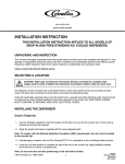
HAND-HELD
TRANSMITTER
CAB MOUNTED
RECEIVER /
INTERFACE UNIT
UP TO
300 FT
BOBTAIL FLAMMABLE
GAS DELIVERY VEHICLE
Figure 1-1. The Remote Shutdown System
The Hand-held Unit
The Hand-held unit (or Transmitter):
•
Travels with the dispense operator
•
Provides the required shutdown controls.
•
Has additional controls for other optional operational features
•
Is small, light-weight, and can easily be looped to a belt or placed
in a pocket for accessibility .
The Receive/Interface Unit
The Receive/interface unit:
•
•
Is Installed in the delivery vehicle cab and
Connects to the appropriate vehicle systems to enable shutdown.
The Hand-held remote Transmitter:
•
Communicates to the Receive/interface unit over a wireless
RF link
•
Can cause the Receiver/interface unit to Disable the flammable
liquid delivery.
The Remote Shutdown System:
•
Provides a remote means of closing the internal valve and shutting
down the vehicle engine when correctly installed and wired.
•
Once activated, will lockout the shutdown function and effectively
prevent the vehicle from being remotely.reactivated.
1-3
Safety Considerations
Unpacking
On receipt, carefully unpack and refer to the packing slip to determine
that all parts are present and no transit damage has occurred.
The remote shutdown device should consist of the following items:
•
Blue Hand-held Transmitter 1, 2, 3, or 4 function
•
Receiver/interface enclosure - Black/blue
•
Installation Instructions - (this manual)
1-4
Chapter 2,
Specifications
Table 2-1. Specifications
Overall System Specifications
RF SCHEME
Operating Frequency - 331.165 MHz, FSK
FCC Part-15, non-licensed, On-Demand
CONTROL RESPONSE TIME(S)
>100 m-sec (RF and electrical response)
~500 m-sec (when including pneumatic components)
SECURITY
32 bit security code
OPERATING RANGE
Up to 325 ft (100 meters)
WARRANTY
12 months from date of shipment
Hand Held Transmitter Specifications
PHYSICAL DATA
4.75" L x 2.15" W x 1.1" T, 155 grams w/ batteries
PACKAGE
Fiber Reinforced Nylon, MSA overlay labeling. IP65
POWER
~10 mW, 3VDC - from 2 x AA batteries
RF COMMUNICATIONS
331.165 MHz, non-licensed, FCC Part-15.
INPUTS
4 discrete inputs (buttons)
OUTPUTS
1 discrete output (Status LED)
Receiver/Interface Unit Specifications
PHYSICAL DATA
8.25" L x 5.0" W x 5.35" T; 2.5 lbs. (1,100 grams)
PACKAGE
Fire Retardant ABS Plastic / Fiber reinforced Nylon.
REQUIRED UTILITIES
12 VDC, 2 AMP, from switched source and
Pneumatic air supply (when required)
RF COMMUNICATIONS
331.165 MHz, non-licensed, FCC Part-15.
INPUTS
RF Only
OUTPUTS
One relay, 20 Amp max (Engine Disable)
Up to Three Pneumatic (Optional)
PNEUMATIC AIR SUPPLY
(WHEN REQUIRED)
Clean and Dry
Minimum 25 psig.
Maximum 150 psig
2-1
Chapter 3,
Physical Description and Installation
3-1
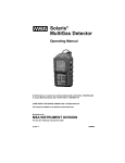
The Hand-held Transmitter
The operator uses the Hand-held Transmitter remote control unit to
initiate a Shutdown. Depending on the configuration of your system, the
Transmitter may have other remote functions. It is powered by two
alkaline batteries that should give months of service.
TEACH
BUTTON
#1 / PTO
BUTTON
RF TRANSMIT
& STATUS LED
TEACH
STOP (SHUTDOWN)
BUTTON
#1
PTO
#2 / THROTTLE
BUTTON
Figure 3 1: The Hand-held Transmitter
Transmitter Setup
The Transmitter:
•
Requires two AA size alkaline batteries
•
LED flashes Green when battery power is sufficient.
•
LED flashes Red when battery power is low.
When batteries are low:
•
Operating distance shortens
•
Replace with new batteries.
3-2
STOP
#2
Throttle
MSA
The STOP button:
• Is used to initiate the remote Shutdown:
•
When the STOP button is pushed, the engine shutdown relay
opens the truck engine run circuit and (when present) provides
the appropriate pneumatic output to stop all LPG delivery.
The TEACH Button:
• Is used for teaching the receiver the appropriate 16-bit
identification code to work with a given Transmitter Interface Unit.
•
See Chapter 4, "Operating Procedures" for the specific Teach
procedures.
The #1 (PTO) Button:
• This #1 (or PTO, when present) button is used in the Teach
procedure.
•
This button is also used to operate the vehicle Power Take Off
(PTO) or vehicle clutch, when that optional configuration is present.
The #2 (Throttle) Button:
• This #2 (or Throttle, when present) button is used in the Teach
procedure.
•
This button is also used to operate the vehicle Throttle to step up
the engine idle speed (when that optional configuration is present.)
3-3
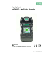
The Receiver/Interface Unit
The receiver/interface unit is made up of two separate modules that
each provide a dedicated function. The modules are wired and bolted
together (there is no reason to service or separate them). The functional
modules are:
•
The Radio Receiver module and
•
The Vehicle Interface module.
ATTACHED
RF ANTENNA
RADIO RECEIVER
MODULE
VEHICLE INTERFACE
MODULE
VEHICLE INTERFACE
BULKHEAD CONNECTOR
Figure 3-2. The Receiver/Interface Unit
•
The Vehicle Interface Module:
•
Contains hardware and wiring connections for the
shutdown system-to-vehicle interface.
•
3-4
All wiring connections to the vehicle are done through the
vehicle interface bulkhead connector and the provided
vehicle interface cable assembly (FIGURE 3-3).
VEHICLE END
15 ft
Long
INTERFACE BOX
CONNECTOR
RED
BLK
BLK
WHT
Figure 3-3. Vehicle Interface Cable Assembly
•
•
Is designed primarily to provide a remote shutdown function.
•
When correctly installed and wired, it can provide the
operator with a remote means of closing the internal valve
and shutting down the vehicle engine.
•
Once activated, the remote shutdown device will lockout
the shutdown function and effectively prevent the vehicle
from being remotely reactivated.
•
To reset the device, remove the 12-VDC supply from the
electronic module (depending on the actual installation) by:
•
Switching OFF the vehicle ignition or
•
Releasing the park brake.
In the BASIC system configuration:
•
The vehicle interface module houses only the engine shutdown
relay, which is:
•
Mounted to the lid of the module enclosure and
•
Pre-wired to the radio Receiver module and the vehicle
interface bulkhead.
3-5
•
In the PLUS system configuration:
•
The Vehicle Interface module houses the engine shutdown
relay and the required primary pneumatic output hardware,
which includes:
•
•
•
Two pneumatic bulkhead connectors mounted on the
opposite end from the electrical connectors
•
The top bulkhead is for incoming pneumatic air and
•
The bottom one is for the primary pneumatic output
The pilot-operated solenoid valve that controls the primary
pneumatic output air
•
This valve is pre-wired to the radio Receiver module
and actuates when power is applied to the unit
•
Pushing the STOP button on the remote causes this
valve to exhaust
The breather is installed in the box to allow venting
pneumatic air to exit the enclosure.
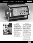
PNEUMATIC
CONNECTIONS
VEHICLE
INTERFACE
CONNECTION
SOLENOID OUTPUT
FOR BELLY VALVE
(SHOWN WITH LID OFF)
PTO/THROTTLE
OPTIONAL VALVES
VEHICLE
INTERFACE
CONNECTION
(SHOWN WITH LID OFF)
TO RADIO
MODULE
OUTPUT RELAY
RSS BASIC
RSS PLUS
RSS DELUXE
Figure 3-4. Vehicle Interface Module Configurations
3-6
•
In the DELUXE (fully optioned) configuration, the vehicle interface
module houses the:
•
Engine shutdown relay
Required primary pneumatic output hardware
•
Two additional solenoid valves for PTO and Throttle outputs
Two pneumatic bulkhead connectors mounted on the opposite
end from the electrical connectors.
•
The additional pneumatic hardware includes:
•
Two additional pneumatic bulkhead connectors for the PTO
and Throttle air outputs. Supply air to the two valves comes
from, and is controlled by, the primary pneumatic solenoid
valve
•
Two electric actuated solenoid valves (for PTO and Throttle)
pre-wired to the radio receiver module.
3-7
Installation Details
Pre-Installation Checks
Prior to installing the emergency shutdown device, make the following
pre-installation checks:
•
Check Transmitter operation:
1. Turn the Transmitter over and open the battery access cover
with a coin (FIGURE 3-5).
Figure 3-5. Transmitter Battery Access
2. Install two AA cell batteries (Duracell or equivalent) and close
the battery access cover.
3. Press the RED Shutdown button and simultaneously check
that GREEN LED at the center top of the case, next to the
RED button (FIGURE 3-1) is flashing brightly.
4. Release the RED button.
•
The LED should stop flashing
5. Repeat this test with each of the remaining BLACK buttons
6. If the Transmitter passes these tests, set it aside until later in
the installation process.
3-8
Installation Checklist
1. Place the enclosure at the rear of the vehicle cab, in the selected
mounting location.
2. Position the enclosure so the end with the wire compression fitting
faces the cab location where the wire harness will be run.
NOTE: Install the Receiver/interface unit where it is not
susceptible to damage from tool boxes, fire extinguishers
and general clutter. To improve communication reliability
and prevent damage, keep the receiver antenna as clear of
clutter as possible. Then, mark the position of the four
mounting holes (by using the enclosure as a template or
by working from the dimensions shown in FIGURE 3-6).
Figure 3-6. Receiver/interface Enclosure
2. Drill four, 1/8-inch pilot holes for #6 sheet metal screws.
3. Using suitable (customer-provided) mounting screws, securely
mount the electronic module enclosure at the desired location.
4. When drilling any holes through the vehicle cab, ensure that the
sealing is restored once the enclosure is mounted.
3-9
Pneumatic Connections (FIGURES 3-7 through 3-9)
Figure 3-7. Basic Pneumatic Connections
Figure 3-8. RSS Plus Pneumatic Diagram
3-10
Figure 3-9. RSS Deluxe Pneumatic Diagram
•
All remote system pneumatic connections are made at the two
bulkhead air fittings mounted in the enclosure base (FIGURE 3-7):
•
Air "IN" is terminated at the upper-right side bulkhead fitting
•
Air "OUT" to the internal valve operating cylinder is terminated
at the bottom-right hand side bulkhead fitting.
•
The following assumes that a suitable air cylinder exists to provide
the mechanical force to operate the internal valve.
•
These pneumatic connections form an integral part of the
"Emergency Shutdown" system. When correctly installed,
Emergency Shutdown feature activation switches OFF the engine
and causes the internal valve to close.
" CAUTION
All pneumatic fittings and connection tubing used for this
installation must be DOT-approved; substitution with components of a lesser standard is expressly forbidden.
While referring to the pneumatic connection diagram shown in FIGURE
3-7, perform the following installation:
1. Locate the tubing run that connects the internal valve air cylinder
directly to the main air supply.
2. At a suitable location, cut or disconnect one end of this tubing so
that the air supply for the internal valve air cylinder can be rerouted
3-11
through the interface enclosure.
3. Using 1/4" DOT-approved tubing, reconnect the air cylinder to the
air supply by routing the air supply into the remote enclosure at the
upper right-hand fitting (AIR IN) and out to the cylinder at the lefthand fitting (INTERNAL VALVE) as shown in FIGURE 3-7.
4. All air lines should be secured in place with suitable ties and
protected from abrasion and wear when passing through
bulkheads and fire walls.
Operational Test
Before running the following test, ensure that:
•
Installation is complete
•
All access covers are replaced
•
All additional electrical wiring and pneumatic piping is neatly
installed and clipped in place (where necessary)
•
All cable joints are protected.
1. Start the truck.
2. Engage the emergency brake.
•
The internal valve should now open.
3. Press the RED Emergency Shutdown button on the remote
handset and check that the:
•
Engine stops
• Internal valve closes.
4. Press the RED Emergency Shutdown button on the remote again
and confirm that nothing happens.
5. Switch OFF the vehicle ignition and release the emergency brake.
6. Make sure the power LED on the Receiver turned OFF.
•
3-12
The installation is now complete.
Wiring Checklist
NOTE: Disconnect the battery before using any power tools or making
any modifications to the vehicle.
When making connections to the vehicle electrical system,
ensure that all cabling is routed away from any heat source and
adequately protected where wires and cables pass through
steel bulkheads and/or firewalls.
1. To correctly install the shutdown device, locate the following
connection points on the vehicle:
•
•
A key switch-controlled 12 VDC supply (live only when the
Bobtail is setup to deliver product); a pressure switch in the
park brake system or similar device could provide this function.
The switch contacts must always be:
• connected into the 12-VDC feed wire (RED wire) and
• fed by the keyed 12-VDC supply.
NOTE: this connection is important when controlling vehicles with
Fisher pneumatically-operated internal valves.
a. Connect the black wire of the red and black power cable wires
to a good clean chassis ground.
b. Use the vehicle wiring diagram to locate the feed wire which
controls the engine run device; when this connection is broken,
the vehicle engine shuts down.
•
Depending on engine type, the run device could be:
•
the ignition system on a gas engine or
•
an electrically-controlled fuel pump or solenoid on a diesel
engine.
Once the connection points are located, wiring installation is as follows:
1. Disconnect the vehicle battery.
2. Disconnect or cut the feed wire to the engine run device (see
vehicle service manual).
3. Extend the connections by using suitably-rated extension wires.
•
This will allow the normally-closed relay contacts on the truck
interface relay to control the engine shutdown function.
•
Any wire splices should be made with insulated crimped or
soldered connections.
3-13
4. Route the power and control cables to the Receiver/interface unit
and connect the four-pin cannon plug to the mating connector in
the end of the interface enclosure using a 1/4-turn.
5. Once these connections are made:
a. Reconnect the vehicle battery and start the engine.
b. Check that the electronic module is not powered up (assumes
vehicle is road-ready) by making sure the RED power ON LED,
is not ON.
c. Using the remote Transmitter to operate the remote shutdown
function, press the RED shutdown button.
•
The vehicle engine should continue to run.
6. Set the bobtail into its product-delivery configuration and again
press the RED shutdown button.
•
The vehicle engine should now shutdown and lockout.
•
Continued operation of the RED shutdown button should have
no further effect; to ensure this, check the RED power ON LED
and the RED relay status LED .
•
These LEDs should be ON and remain ON for repeated
operation of the RED shutdown button.
7. If the engine does not shutdown when the RED shutdown button
is pressed, see Chapter 5, "Troubleshooting Guidelines".
8. This completes the installation of the basic remote shutdown
system for a vehicle fitted with a REGO Flowmatic® internal valve.
Electrical Installation Test
Before running the following tests, ensure that the:
•
Installation is complete
•
Access covers have been replaced
•
Additional electrical wiring and pneumatic piping is neatly installed
and clipped in place where necessary
•
Cable joints are suitably protected.
1. With the vehicle in road-ready condition, start the engine.
2. Use the remote transmitter and attempt to shutdown the engine.
• Operation of the shutdown function should have no effect
• Engine should continue operating normally.
3-14
3. Set up the Bobtail as it would be set for normal propane delivery;
again, operate the shutdown function.
•
This time, the engine should stop running and the internal
valve (belly) should close.
4. Once the shutdown function is activated, it should not be possible
to re-open the internal valve (belly) with the RED shutdown button.
5. On installations with multiple auxiliary functions, these will be
disabled after an emergency shutdown has been instigated.
6. If everything checks out, reset the electronic module and restart
the engine.
7. Move away from the vehicle to a distance of 300 ft and again
operate the shutdown device.
• The engine should again shut down.
8. Where additional pneumatic components have been added to the
control system, refer to the installation manual for those
components to complete this installation.
Final Installation Checklist
Before running the following tests, ensure that:
•
Installation is complete
•
All access covers are replaced
•
All additional electrical wiring and pneumatic piping is neatly
installed and clipped in place (where necessary)
•
All cable joints are suitably protected.
1. Start the engine of a road-ready vehicle.
2. Using the remote Transmitter, attempt to turn OFF the engine.
•
This shutdown function should have no effect; the engine
should continue operating normally.
3-15
Chapter 4,
Operating Procedures
Basic Operation
NOTE: The user must understand and follow all local operational procedures and regulations.
The internal valve is ready to deliver product when:
•
Power is applied to the system
•
The truck is parked and
•
The engine is running.
On the Basic Plus and the optioned systems:
•
The Internal (belly) valve output from the interface unit pressurizes
and opens the actuator cylinder on the belly valve
•
When the PTO is engaged, the pump allows for delivery of product.
In the event as of an accidental discharge of Flammable product, the
system waits for a Transmitter command to:
•
Turn OFF the engine of an LPG delivery truck (parked, with its
engine running, and prepared to deliver product) and
•
Close the internal valve on the tank.
To provide this Transmitter command, press the Transmitter’s red STOP
pushbutton (FIGURE 3-1) from up to 300 feet away from the truck. The
engine will shutdown which stops the pump from pumping:
•
The internal valve is closed by the pump shutdown (Rego
Flowmatic ® valves) or
•
A pneumatic actuating cylinder is exhausted through the interface
unit to retract and close the internal valve.
4-1
On the optional PTO and Throttle control systems (Optioned systems):
•
The added safety of remote pump engagement and idling up the
engine RPMs, is added to the system
•
The system is first powered when the truck is parked
•
At this time, the PTO and Throttle pneumatic outputs are
exhausting
•
A single press of the PTO and/or Throttle button maintains a
pressurized output for these functions.
Daily Functional Safety Inspection Test
1. Start the truck.
2. Engage the emergency brake.
• The internal valve should now open.
3. Next, press the RED Emergency Shutdown button on the remote
handset.
4. Check that the:
• Engine stops
• Internal valve closes.
5. Press the RED Emergency Shutdown button on the remote again
and confirm nothing happens.
6. Finally, switch off the vehicle ignition and release the emergency
brake.
7. Make sure the power LED on the Receiver turned OFF.
8. On the RSS Deluxe system:
If everything functions correctly in the above tests, press the PTO
button and make sure the pump starts to operate.
NOTE: When the PTO button is pressed again, the pump should
stop operating.
9. When you press the Throttle button, the engine RPM should rise
up to the predetermined point for pumping safely.
NOTE: When the Throttle button is pressed again, the engine
RPMs should lower back down to the truck’s nominal
speed.
4-2
"Teaching" a Receiver a new Transmitter
Remote Setting
Remote setting allows you to pair the new Transmitter and Receiver if
either becomes damaged. In order for the radios to work, the
Transmitter and Receiver must have the same ID codes and frequency.
Using remote setting will set the Transmitter and Receiver to have the
same ID codes.
Ensure the following conditions are met before attempting the Remote
Setting procedure.
•
The Transmitter and Receiver are of the same model and
frequency.
•
Place the Transmitter as close as possible to the Receiver to avoid
any interference.
•
Turn OFF the Receiver power; then, turn it ON again.
•
Complete the "Remote Setting" procedure within four minutes after
turning ON the Receiver.
•
The Receiver will NOT accept the remote setting signal after
four minutes have passed.
Remote Setting Instructions (see FIGURE 3-1)
1. Press and hold the Transmitter STOP pushbutton.
2. Press and hold the #2 THROTTLE pushbutton.
3. Press the TEACH pushbutton four times.
4. Release STOP and DOWN pushbuttons when the red light flashes.
5. Start the system by following the "Basic Operation" procedure
earlier in this chapter.
NOTE: In case the remote setting procedure fails, repeat the instructions above within four minutes.
The remote setting procedure will update the ID code only. It
will not change function settings or frequency.
All same model systems on the same frequency will be paired
with the Transmitters ID code within the operating distance.
4-3
" WARNING
Inspect the unit daily. Inspection must include testing the
emergency stop and other safety devices and functions. If
there is any doubt, operation must be stopped immediately
and problems be corrected before operation is resumed.
Failure to follow this warning can result in serious personal
injury or death.
4-4
Chapter 5,
Troubleshooting
Troubleshooting Guidelines
Table 5-1. Troubleshooting Guidelines
ERROR CODES
CHECK
ACTION
Red LED flashing quickly
(every 0.2 sec) when any
pushbutton is pressed
One of the pushbuttons is jammed
If a problem is found, contact
the distributor for repair
System is not properly powered
according to the instructions.
If a problem is found, contact
the distributor for repair
Transmitter LED flashes
slowly (every 0.5 secs)
Transmitter memory is defective.
Contact the distributor for repair.
Receiver Error LED*
flashes slowly
(every 0.5 sec)
Receiver memory is defective.
Contact the distributor for repair.
When truck parked and
set to deliver product,
engine does not shut down
when transmitter RED
STOP button is pressed
1) Is receiver main power LED ON?
YES- go to check # 2
NO- See Chapter 3, "Receiver
Interface Unit" and check power
cable connections.
Check receiver power fuse
2) Is receiver cover relay activation
LED ON?
YES- Receiver successfully
received & acted on a transmitter
command. Go to check #3
NO- Go to check #4
3 Does receiver cover Emergency
Shutdown LED turn ON when
pressing RED transmitter button?
YES- System is working properly.
See Chapter 3, "Receiver
Interface Unit" & check the shut
down interface connections
NO- Go to check #4
4) Does transmitter front status LED
flash RED when a button
is pressed on the transmitter?
YES- Transmitter battery is low or
unit requires service.
No indicator lit on transmitter also
means same as stated above
NO- Go to check #5
5) Does transmitter front status LED
slowly flash green when a button
is pressed on the transmitter?
YES- Go to check #6
NO- transmitter requires service.
Go to check #8
*The receiver Error LED is inside the receiver; observe appropriate precautions when opening the unit.
5-1
ERROR CODES
CHECK
6) Does receiver inside cover
squelch LED go OFF when
transmitting to it?
code receiver
ACTION
YES- Transmitter & receiver ID
codes don’t match;
go to check #8
NO- Transmitter & receiver are
not on same channel. Possible
bad transmitter crystal. Possible
interference on that channel. Or,
go to check #7
7) Does the receiver inside-cover error
LED flash?
YES- Receiver requires service
NO- Go to check #8
8) Does a spare transmitter set up for
this system properly operate the
system?
YES- Transmitter requires service
NO- Check the receiver fuses; If
problem persists, receiver
requires service
Vehicle engine shuts down
when RED STOP transmitter
button is pressed & truck is
NOT set to deliver product 9) See Chapter 3, "Receiver
Interface Unit" & check the power
cable connections. Ensure that
power to system is ON only when
truck is parked, running, &
set to deliver product
Vehicle engine shuts down
when the transmitter
RED STOP button is
pressed, but only at close
range from the truck parked
& set to deliver product
10)
Does receiver inside-cover
squelch LED turn OFF when
transmitter is not transmitting?
Use 12-volt source that is hot only
when ignition switch is ON; run
that source through a pressure
switch that is closed when park
brake is set or PTO is engaged
YES- External interference source
on system’s operating frequency;
Change channel on this system to
eliminate interference
NO- Go to check #11
11)
Does transmitter front status
LED flash RED?
YES- Low batteries effect system
range
NO- Go to check #12
12)
Does spare transmitter set up for
this system properly operate the
system?
YES- Transmitter requires service
13)
Any obstructions (metallic) on or
near the receiver antenna?
Is the antenna broken?
YES- Remove obstructions;
broken antenna requires repair
NO- Go to check #13
NO- receiver requires service
5-2
ERROR CODES
CHECK
Vehicle engine shuts down
when transmitter RED STOP
button pressed & truck is set
to deliver product, but internal
(belly) valve doesn’t close 14)
15)
Identify valve type used on
delivery truck
Is air exhausting through truck
interface enclosure vent, removing air pressure from
the air out port?
ACTION
A Rego Flowmatic® closes when
pump pressure is lower than tank
pressure. RSS system shuts
down engine (& pump); problem
is with truck, not with system.
Any other valve requires air pressure through actuator to open it.
Releasing actuators air closes the
valve via a spring. Solenoid valve
used for the internal valve control
is stuck, exhaust port is plugged,
or the actuator or spring is stuck
YES- System OK; problem is
else-where on the truck
NO- Solenoid valve for internal
valve control stuck; exhaust port
plugged or requires service
The internal (belly) valve
does not open when truck
is parked and set to
deliver product
16)
Is there at least 25 PSI of air
feeding receiver INPUT port?
YES- Go to check #17
NO- 25 PSI required to properly
operate internal valve.
Go to check #1
17)
Is receiver main power LED
ON ?
YES- Go to check #18
NO- With no power to system, the
solenoid valve used for controlling
internal valve cannot open.
See Chapter 3, "Receiver
Interface Unit"
18)
Is air coming out of the OUT
port feeding the belly valve
actuator?
YES- Problem is else-where on
truck or in the air plumbing
NO- receiver/interface requires
service
Throttle output does nothing
when transmitter Throttle
button pressed;
emergency stop works
19)
Is receiver throttle LED ON?
YES- Go to check #20
NO- If a spare transmitter fixes
the problem, transmitter requires
service. If spare transmitter does
not fix problem, receiver/interface
requires service
5-3
ERROR CODES
CHECK
20)
Is air coming out of the Throttle
output port?
ACTION
YES- Problem is else-where on
truck or in the air plumbing
NO- receiver/interface unit
requires service
PTO output does nothing
when transmitter PTO
button pressed;
emergency stop works
21) Is receiver PTO LED ON?
YES- Go to check #22
NO- If spare transmitter, fixes
problem, transmitter requires
service. If spare transmitter does
not fix the problem, receiver/inter
face unit requires service
22)
Is air coming out of the PTO
output port?
YES- Problem is else-where on
truck or air plumbing
NO- The receiver/interface unit
requires service
Change Fuses
1. Remove the four, 10 mm nuts and their washers from the Receiver
enclosure.
•
To remove the 1.5 amp power fuse (located by the Receiver
cable harness entry) press the fuse cover and turn counterclockwise with a flat screwdriver to open.
2. Remove the old fuse and insert a new fuse (of the same rating and
style) into the cover first; then, place this fuse (with the cover) into
the fuse holder base.
3. Press the fuse cover and turn clockwise with flat screwdriver.
NOTE: The control voltage fuse is a yellow, 20-amp blade automotive
style fuse near the antenna side of the Receiver
fuse.Obtaining Replacement Parts
To obtain replacement parts, address the order or inquiry to:
•
5-4
Mine Safety Appliances Company
Instrument Division
P.O. Box 427
Pittsburgh, PA 15230-0427
or call, toll-free, 1-800-MSA-INST.
" WARNING
Use only genuine MSA replacement parts when performing
any maintenance procedures provided in this manual.
Failure to do so may seriously impair instrument performance. Repair or alteration of this system, beyond the scope
of these maintenance instructions or by anyone other than
authorized MSA service personnel, could cause the product
to fail to perform as designed and persons who rely on this
product for their safety could sustain serious personal
injury or death.
Table 5-2. Replacement Parts List
PART
RSS Basic System Receiver
PART NO.
10061256
RSS Plus System Receiver
10061257
RSS Deluxe System Receiver
10061258
RSS Transmitter
10061255
5-5
Appendix A,
Drawings
Figure A-1. Basic Configuration
A-1
Figure A-2. Basic Plus Configuration
A-2
Figure A-3. Deluxe Configuration
A-3
IN TER FAC E
R ELAY
J1
TM 2000 R X
Figure A-4. RSS Basic Wiring
A-4
Figure A-5. RSS Plus Wiring
A-5
TM 2000 R X
IN TER FAC E
R ELAY
J1
IN TER FAC E
R ELAY
J1
TM 2000 R X
Figure A-6. RSS Deluxe Wiring
A-6
MAIN POWER
RELAY ACTIVATION
PTO (OPTION)
THRTL (OPTION)
EMERGENCY SHUTDOWN
MSA
10800-MSA-INST
Figure A-7. Unit LED Detail
A-7