1
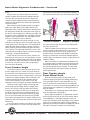
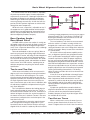
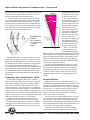
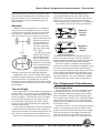
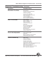
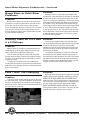
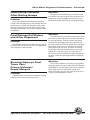
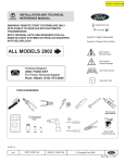
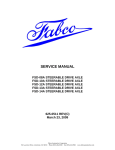
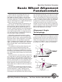
Specialty Products Company
Basic Wheel Alignment
Fundamentals
Wheel alignment technology advances continuously with the introduction of new makes
and models of vehicles, engines, transmissions/
transaxles, steering and electronic suspensions.
Two wheel alignment is quickly becoming obsolete
and four wheel alignment is rapidly being incorporated on many of the new models.
With the technology being incorporated in the
newer vehicles, it’s not just the front tires which
steer the vehicle. Many manufacturers now use
four wheel steering and complex electronic suspensions. Specific procedures must be followed to
ensure proper wheel alignment. On these newer,
more sophisticated vehicles, an alignment technician can easily end up misaligning the wheels by
not following the proper procedures.
With today’s computerized vehicle systems,
improperly aligned wheels can effect engine performance, ride, tire wear, steering and premature
component failure. Wheel alignment is the proper
adjustment of ALL the interrelated suspension
angles. In alignment terminology, these adjustment
angles are called caster, camber, toe-in, steering
axis inclination (SAI), vehicle ride height and toeout on turns.
The method of checking wheel alignment will
vary with the type of equipment being used.
Although the outcome of the alignment must be
the same, it is important to follow the instructions
furnished by the manufacturer. On most new vehicles, only camber and toe angles are mechanically
adjustable.
Some technicians may encounter a vehicle that
will not be able to achieve the specified angles. On
these vehicles, a more thorough inspection of all
the interrelated components must be done. Most of
the time, replacing worn or even marginally worn
parts will correct the out-of-specification vehicle.
Wheel alignment should never be performed on a
vehicle with worn or defective chassis/suspension
components.
The technician should consult with the vehicle
owner on any particular problem before an attempt
at wheel alignment is made. Talking with the
owner first will help diagnose the problem area.
A thorough visual inspection of the vehicle should
then be performed. Record visual signs of tire wear
and any ride height imperfections to ensure these
areas are corrected prior to alignment adjustments.
Test driving the vehicle as part of the diagnostic
process is essential. Some vehicles may not need
an alignment. Instead, the steering wheel may
need to be centered or the suspension may need
repaired. A test drive will be helpful in diagnosing
a vehicle problem. Follow the pre-alignment procedure as a guide to ensure all areas are inspected
before actual adjustments are made.
Alignment Angle
Terminology
Caster Angle
Caster is the angle between an imaginary line drawn
through the upper and lower steering pivots and a line
perpendicular to the road surface (viewed from side of
vehicle). If the top of the line tilts rearward, the vehicle
is said to have “POSITIVE” caster. If the top of the line
tilts forward, the vehicle is said to have “NEGATIVE”
+
0º
Positive
Caster
Lead
Point
Wheel
Contact
Point
0º -
Specialty Products Company • Toll Free Hotline 800-525-6505
Negative
Caster
1
Basic Wheel Alignment Fundamentals - Continued
caster.
Positive caster can also be defined as when the
spindle is tipped so that the pivot support centerline
intersects the road surface at a point in front of the
initial tire contact. Negative caster would then be the
center line intersection to the road surface behind the
initial tire contact.
Most vehicles produced today do not have adjustable caster angle. Many early model vehicles have
adjustable caster in which road crown is compensated
for (along with camber). By setting the caster angle on
the driver’s side 1/2 degree less than the passenger side
for positive caster specifications or 1/2 degree more for
negative caster specifications, the road crown should
not cause vehicle pull in either direction.
Vehicles equipped with manual steering use very
little positive or negative caster. This helps reduce the
steering effort at the steering wheel. The advantage of
caster adjusted toward negative is greater maneuverability; however, direction stability on open road driving is reduced. The advantage of positive caster is the
strong directional stability and the ease of returning the
steering to a straight-ahead position.
Caster will not cause tire wear unless extreme misadjustment or worn parts are involved. Always set caster (if adjustable) to specifications and within 1/2 degree
from side to side. Keep road crown in mind and adjust
as necessary if a pull is present after a proper alignment has been completed.
Front Camber Angle
The camber angle will affect the wear on the inner
or outer edge of the tire. Camber is the inclination of
the centerline of the wheel from the vertical as viewed
from the front of the vehicle. Camber angle is measured
in positive or negative degrees. Positive camber is the
outward tilt of the top of the tire. Negative camber
is the inward tilt of the tire at the top. If a tire was
absolutely vertical, the degree of camber would be zero.
Unlike the caster angle, camber will change with
vehicle load and ride height. With the weight of the
driver in the vehicle, front left camber will increase
and front right camber will decrease. As rough road
conditions are encountered, the downward thrust of
the vehicle body will cause front camber to go negative. As the vehicle body movement returns upward,
front camber will go positive. As camber oscillates, toe
adjustment will also change with each movement of the
control arm.
A tire with positive camber can influence the vehicle
with a directional pull. The vehicle will go towards the
2
side that has the tire with the most positive camber. It is
the normal tendency of the tire to roll around the center
-
0º +
Positive Camber
0º
Negative Camber
of a circle when the top of the tire is inclined towards
the center of that circle.
Positive camber tends to place the tire-to-road contact area nearer the point of load. This assists in easier
steering and forces the thicker inner portion of the
spindle to carry most of the load. Modern suspension
design has reduced the need for considerable positive
camber. Many manufacturers specify a slight amount of
negative camber.
Some manufacturers recommend an additional 1/4
to 1/2 degree positive camber on the left wheel to compensate for road crown. The car will then pull toward
the side with greater positive camber. This will offset
the pull effect of the road crown. Always set camber
within specifications.
Rear Camber Angle Front Wheel Drive
Rear wheel camber angle is being relied on for
improved steering and general handling performance.
In the past FWD vehicles and independent rear suspension vehicles were most likely to have adjustable
rear camber. On vehicles currently being produced, rear
camber adjustment capabilities are being found on all
types of models.
Note: Always use full-floating tables under wheels
whenever alignment is being done.
When alignment problems are reported on vehicles
with fixed rear axles and no rear wheel camber adjustment capabilities, a thorough inspection of the rear
suspension should be made. Damaged or worn components can cause alignment and/or steering problems.
Replacing or repairing the defective components should
bring the rear wheel assemblies into specification.
Specialty Products Company • Toll Free Hotline 800-525-6505
Basic Wheel Alignment Fundamentals - Continued
On vehicles where rear wheel camber is adjustable,
all previous precautions apply. If camber adjustment
requirements are excessive, a thorough inspection must
be performed. Replacing any defective components
could bring the camber into specification and adjustment may become unnecessary. As with the front suspension, DO NOT perform alignment on vehicles with
damaged or worn components.
Whether the rear suspension is adjustable or not, if
all components are in good condition and the proper
specifications cannot be obtained, aftermarket correction kits may be needed. Many of these kits are available from Specialty Products Company.
Rear Camber Angle Rear Wheel Drive
On RWD vehicles, where rear camber is usually not
adjustable, camber will normally be fixed at zero. Even
though this angle cannot be changed through adjustment, if rear suspension abnormalities exist, a thorough
inspection must be made.
Not to be overlooked are the rear springs. Worn or
weak rear springs will alter riding height and because
of a reduction in tension, will bring the shock absorbers
out of the optimum range of their dampening ability.
The result will be excessive tire movement. This condition reduces operator control and contributes to abnormal tire wear. As in FWD vehicles, replacing worn or
defective components may bring rear wheels within
specification.
Toe-In and Toe-Out
Unlike caster and camber, which are measured in
degrees, toe is most frequently measured in fractional
inches, millimeters or decimal degrees. The system
of measurement selected will depend on the type of
equipment available. An incorrect toe setting is one of
the main alignment factors that cause excessive tire
wear. Front and rear toe are the same in definition, with
the adjustment capabilities and procedures being the
only actual difference.
Toe is the difference between the leading edge (or
front) and trailing edge (or rear) of the tires. Toe-in is
the measurement in fractions of an inch, millimeters or
decimal of degrees that the tires are closer together in
the front than they are in the back. Toe-out is the same
measurement, except the tires are further apart in the
front than in the rear.
Some manufacturers measure the angular change
from straight-ahead in degrees. Slight toe-in is preferred to toe-out on most vehicles because steering is
aligned while the vehicle is stationary. When the vehicle
Toe
In
Toe
Out
is moving, linkage components flex causing a change in
alignment angles. This is classified as “Running Toe.”
Running toe should be zero to maximize tire life and
achieve the least rolling resistance.
The usual tendency is for the tires to turn outward
while the vehicle is in motion, so most vehicles are
designed with a static toe-in setting. The static toe-in
setting will become zero as the linkage flexes when the
vehicle is in motion. Always set toe to the manufacturer’s specifications.
On vehicles with toe adjustment capability on the
rear, an alignment specialist can go beyond manufacturer’s specifications according to vehicle usage and
customer requirements. With the proper equipment,
the rear axle can be adjusted to perform aggressively
toward demanding load and road conditions. Vehicles
with FWD and independent rear suspensions are more
likely to have adjustable rear toe. As with rear camber,
properly adjusted rear toe will contribute to improved
steering and handling characteristics. Full floating
tables must be used under the rear tires whenever toe
is to be adjusted.
If rear toe is out of specification a thorough inspection must be done, whether or not rear toe is adjustable. Components found to be defective must be
replaced. On vehicles that do not have rear toe adjustment capability and toe is not within specifications,
replacing defective components may bring toe within
specifications.
If proper toe specifications cannot be obtained,
alignment correction kits may have been developed
since the vehicle was produced. Contact Specialty
Products Company to see if any of these types of kits
are available for the vehicle.
Toe-Out on Turns
When a vehicle enters a turn, the outer tire must
travel a greater distance than the inner tire. The tire
center is tangent to the turn circle. If the tires were to
Specialty Products Company • Toll Free Hotline 800-525-6505
3
Basic Wheel Alignment Fundamentals - Continued
remain parallel in a turn, one tire would drag across the
road surface. This would create tire squeal, excessive
tire wear and reduce handling performance.
The outside front wheel must therefore be turned
at less of an angle than that of the inside front wheel.
This will keep both wheels tangent to their respective
turning circles and prevent tire squeal and/or damage.
As the vehicle enters a turn, the tie rod ends will travel
an equal distance, but due to the angle of the steering
arms the tires will progressively toe-out.
Toe-Out on
Turns
(Also referred to
as: Turning Angle
or Turning
Radius)
Although this angle is never adjustable, it is easily
checked on the alignment rack by turning the tires 20
degrees on full floating tables. First turn the front right
tire 20 degrees and read the indicator on the left wheel.
This is the angle of toe-out for the left tire. Repeat
the procedure for the remaining side. Compare reading
with specifications. Readings not within specifications
are an indication that the steering arms are bent and
should be replaced. Never bend or heat components to
repair them.
Steering Axis Inclination (SAI)
Steering Axis Inclination (SAI) can be a difficult
angle to understand. SAI is also referred to as the ball
joint angle or kingpin inclination (on I-Beam suspension). The easiest way to understand SAI is to first
define steering axis. The steering axis is an imaginary
line intersecting the spindle support. In a conventional
steering system, the spindle supports are the upper and
lower ball joints or the kingpins. With MacPherson strut
systems, steering axis is the angle beginning at the ball
joint and extended through the strut assembly.
Viewed from the front of the vehicle, SAI is the
angle between the steering axis and a true vertical
line established through the tire. The SAI is a stability
angle and is measured in degrees. If these imaginary
lines were extended to the road surface, the area cov-
4
ered between them would
be identified as the point
of load or scrub radius.
S.A.I.
The vehicle body will
be
closest to the road surI.A.
face when the wheels are
pointed straight-ahead as
a result of SAI. A spindle
with SAI will have the
outer end of that spindle
at the highest point when
the wheels are pointed
straight-ahead. Therefore,
as the weight of the
vehicle pushes downward,
the spindle will always
attempt to move upward
to return the wheels to a
straight-ahead position.
After a turn, the SAI
helps to return the tires
to straight-ahead position.
SAI also aids in vehicle directional stability by resisting
road irregularities that attempt to turn the wheels away
from the straight-ahead position. SAI produces many
of the same benefits that improve steering stability as
positive caster. Correct engineering of SAI can reduce
the need for high positive camber.
The effect of SAI on directional stability is usually
greater then that of caster. Some vehicles with power
steering require a greater amount of steering wheel
returning force than those with manual steering. SAI
is often used with positive caster on power steering
equipped vehicles to assist in steering wheel returnability.
Camber
Scrub Radius
Scrub radius is the term used to describe the distance between the projected steering axis and the tread
centerline at the road surface. Scrub radius is positive
when the centerline of the tire lies outside the projected
steering axis. It is negative when the centerline of the
tire is inside the projected steering axis. The scrub
radius is a distance measurement and it is therefore
measured in inches or millimeters.
The size of the scrub radius depends on the steering
axis inclination, wheel offset and the distance the spindle centerline is above the road surface. By carefully
considering the correct SAI and the proper wheel offset
for the designed spindle height, the required amount of
scrub radius is designed into the suspension.
Although the spindle height has an effect on the
scrub radius, little can be done to change this height
Specialty Products Company • Toll Free Hotline 800-525-6505
Basic Wheel Alignment Fundamentals - Continued
because tire height is limited by the clearance space
under the fender and body. Since all handling sensations pass between the tire and the road, the scrub
radius provides the necessary feedback to give the
driver road feel.
Setback
Setback or front end squareness is a condition in
which one wheel is rearward of the other. If setback
is present the turning radius will not be correct when
the vehicle turns. With this condition, the tires will
wear very much in the same manner as if they were
under inflated. Generally,
setback is the result of
collision damage. It is
preferable to have the
front tires square with
each other before alignment is done.
Considering the many
different types of alignment equipment available, it is not possible
to cover each checking
procedure. Use the alignment machine manufacturer’s instructions for
checking setback. The
most accurate way of
checking is with four wheel alignment equipment.
Depending on the severity of setback and the type
of alignment equipment being used, false readings can
mislead a technician into thinking that an incorrect
adjustment is within specification. These false readings
are experienced more frequently with two wheel alignment methods.
Thrust Angle
Thrust angle is the line that divides the total angle of
the rear wheels. The rear tires are not just following the
front tires, they are actually establishing direction of the
vehicle. In doing so, a direction of thrust is developed.
The thrust angle created by the rear wheels is used
as a reference for aligning the front wheels. Ideally,
the thrust angle should be identical to the geometric
centerline of the vehicle.
If thrust angle and geometric centerline are identical,
the position of the tires would then form an absolute
rectangle and the front tires could be aligned to the rear
tires, resulting in a perfectly centered steering wheel.
Because of unitized construction, factory tolerances
and a varying degree of damage and/or wear, it is
increasingly unlikely that the axles will be parallel.
When the rear axle projects a different angle than the
front axle, the driver will need to turn the steering
wheel to compensate in order to drive in a straight line.
On situations where the thrust line and geometric
Positive
Thrust
Angle
Negative
Thrust
Angle
centerline are not identical, a thorough inspection of
the rear axle and suspension system must be done.
Replacing defective components should aid in positioning thrust angle close to the geometric centerline.
If the thrust angle is not identical to the geometric
centerline and there are no defective components, align
the vehicle using the thrust angle instead of the geometric centerline. Aligning the front wheels to the thrust
angle is preferred to aligning to the geometric centerline. The ability to do this is a significant advantage of
four wheel alignment. The result should be a straight
steering wheel as the vehicle moves straight-ahead.
Pre-Alignment Procedures
Tire Inspection
Inspection of the tires can help in diagnosing some
wheel alignment failures. The tire wear pattern will
record improper alignment of camber or toe settings.
Some wear patterns associated with improper alignment include single shoulder wear, cupping and feather
edging. Some tire defects are not visually noticeable,
but can affect wheel alignment. Check each wheel and
tire for radial runout.
Proper tire pressure is essential for properly aligning
wheels. The correct pressure not only allows tires to
perform at the standard for which they were designed,
but is directly related to ride height. Remember that
cold tires will register a slightly lower pressure than
tires that are warm for usage. Tires with low pressure
Specialty Products Company • Toll Free Hotline 800-525-6505
5
Basic Wheel Alignment Fundamentals - Continued
will wear both outer edges. Over inflation will wear the
center of the tires.
Tire size and make, if different can cause a vehicle
with accurate wheel alignment to have a directional
pull or non-centered steering wheel. If tire sizes match,
but brands and tread design differ, measure each tire
individually. There is no manufacturer standard that
dictates what the dimension of a given tire size will
actually be.
Ride Height
Alignment geometry angles are established from the
ride height. An improper ride height will affect the
alignment geometry angles. Ride height can be affected
by several different components. Improper tire size,
pressure, or springs (sagged, weakened or broken), will
reduce ride height and cause the geometry angles to be
out of specification.
If enough adjustment is remaining, the alignment
angles may be brought within specifications. This may,
however, produce a substandard wheel alignment. With
the increase of weight and vehicle motion the original
problem will reappear with the possibility of additional
repair requirements.
Several different areas should be measured to
ensure vehicle ride height is at the factory specifications.
Front Component Inspection
If weak or defective components are undetected and
an alignment is done, premature wear and damage can
occur on other components. It is therefore essential
that all components are thoroughly inspected. Adjust or
replace weak or defective components before checking
or making the alignment adjustments.
Check control arms, stabilizer bar, strut rods and
steering linkage for damage, wear indication or bent
components. Look closely at bushings for signs of deterioration and improper positioning. Replace bushings
as necessary. Check, measure and service ball joints,
referring to a ball joint inspection service manual as
necessary.
Check tie rod ends for excessive up and down movement by squeezing the ends. Very little or no up and
down movement should be present. Check idler arm
and pitman arm for excessive play. Idler arm or pitman
arm movement, other that normal turning movement
should not be present. Replace components as necessary.
Check wheel bearing play and service bearings as
6
necessary. Check shock absorbers for leakage and
weakness. Inadequate shock absorbers will not only
affect ridability, handling and alignment, they will also
cause premature failure of suspension components.
Rear Component Inspection
It is important to understand that unrepaired, weak
and/or damaged components will add to the total collective tolerance of the steering/suspension system.
This total tolerance will continuously allow alignment
angles to change during vehicle operation. To maintain
a quality alignment, replace all components which are
not within specifications.
Although some vehicles do not have adjustable rear
suspensions, the rear wheel position is vital to a properly aligned vehicle. With four wheel alignment equipment available, the rear wheels can be checked in
proportion to the front wheels or vice versa. Many
rear wheel specifications are available even on vehicles
without adjustable rear wheels.
If a visual inspection shows no abnormal or defective components, checking rear wheel alignment specifications (if available) will assure there are no hidden
rear wheel components that are damaged or worn. If
the rear wheels are not within alignment specifications,
the technician should begin a thorough check of the
rear suspension system.
Although the rear wheels are not adjustable, components can be replaced. Replacing components, which
are bent or worn, should bring the rear wheels into
specifications. With the rear wheels within specifications, a more accurate front wheel alignment can be
accomplished. If rear suspension is incorrect prior to
alignment, the steering wheel and front wheel geometry will be off center.
Tire Wear Diagnosis
Because of the rigorous routine the front suspension
must endure, the front tires have to work much harder
than the rear tires. Even when the suspension is in
good condition and the alignment is set correctly, the
front tires will wear faster than the rear tires in most
cases. This is the reason for tire rotation at regular
intervals.
When an abnormal condition develops in the suspension system, it will usually affect the tires and ride.
When this happens, one or even both tires can be
affected and begin a wear pattern characteristic of the
problem.
Specialty Products Company • Toll Free Hotline 800-525-6505
Basic Wheel Alignment Fundamentals - Continued
If a vehicle has a suspension malfunction, the wear
pattern of the tire should readily show what the problem is. Typically where multiple malfunctions have
existed for many miles, attempting to get an accurate
diagnosis can be difficult or impossible.
Tire Smooth
On One Side
When a tire is
wearing smooth on one
side, it can safely be
assumed that the worn
area is where road contact is being made. In
this case, not only is the
tire wear being significantly accelerated, but
control of the vehicle
and handling performance are reduced.
The major cause of this tire wear pattern is camber
misadjustment. Incorrect camber adjustment can result
from worn chassis parts, (springs, steering linkage,
bushings, ball joints, etc.) or previous misalignment.
Excessive positive camber will wear the outside edge
of the tire and excessive negative camber will wear the
inside edge of the tire.
Sometimes, incorrect toe adjustment will cause
shoulder wear on one side (outside wear for toe-in and
inside wear for toe-out). To correct the condition, alignment and tire rotation or replacement is necessary.
Feather
Edging
Feather edging will
normally occur if the
toe adjustment is incorrect. Misadjustment of
toe can develop from
defective chassis parts,
incorrect turning radius
or misalignment.
Defective chassis parts
are not the direct cause
of feather edging but
will allow toe to go out of adjustment resulting in a
wear pattern. Any change in the suspension height of a
vehicle will change toe measurement.
Feather edging is identified by sliding the hand
across the tire tread surface. Depending to which
extreme the toe is misadjusted (in or out), sharp edges
will be felt in one direction and smoothness will be felt
in the opposite direction. Feather edging can result in a
direction pull and eventually ruin the tires.
To correct the condition, alignment and tire rotation
or replacement is necessary.
Cupping Appearance
Tires will begin to develop a “cupping” appearance
when the vehicle suspension loses its ability
to absorb “jounce travel.” “Jounce travel” is
the upward movement
of the tire in relation to
the vehicle’s downward
movement. This condition most commonly
occurs with weak shock
absorbers or incorrect
shock application.
Other factors that
should be considered when tires “cup” are the springs,
tire balance and wheel alignment (in this order). As the
springs sag, the shock absorber shaft will be lowered
out of its effective range. When a vehicle has ineffective
shocks and soft sagging springs, the vehicle becomes
susceptible to excessive bouncing.
The downward motion of the bounce will have a
“digging” effect on the tire that produces the low spot
of the cup. As this condition progresses, it will become
self-perpetuating to the point that part replacement
and/or tire rotation will not reverse the damage. When
encountered, defective parts must be replaced and the
tires rotated to the rear or replaced.
When a tire begins to develop bald spots, the most
common cause is an unbalanced or defective tire.
Occasionally, failure to rotate tires at regular intervals
can contribute to bald spots. In either case, the suspension system should be inspected. If defective components are found in the suspension system, consideration should be given as to whether or not the defective
components could have caused the bald spots.
If the wear pattern is not severe, balance and rotation of tires is recommended. In severe cases the tire
should be replaced. Always check the alignment and
adjust as necessary.
This condition usually develops through abuse and
poor maintenance. When tires are repeatedly under or
over inflated the continuous stress can result in cracks
related to fatigue at the tread.
Other possibilities are excessive exposure to high
temperature roads, high speed driving, or carrying
loads that exceed the rated load capacity. In severe
Specialty Products Company • Toll Free Hotline 800-525-6505
7
Basic Wheel Alignment Fundamentals - Continued
cases, strong consideration should be given as to
whether the tire should be replaced with a tire better
suited to the vehicle’s operating requirements. In less
severe cases, the best tires should be rotated to the
front axle. Always check the alignment and adjust as
necessary.
Shoulder Wear (Both Sides)
When a tire is under inflated, the sidewall and contact surface will be forced to fluctuate excessively.
Initially, the contact surface will buckle and the tire will
travel on the edges. The immediate result is shoulder
wear because the outer treads are receiving all road
contact.
The amount of under inflation will determine the
amount and severity of the tire wear. Consideration
should also be given as to whether the tire should be
dismounted for inner sidewall damage inspection. This
can result from excessive heat buildup due to the added
load displacement stress on the sidewalls. Check tires
for slow leakage and repair as necessary.
Center Wear
If a tire shows signs of accelerated wear in the center
of the tire tread, it has most likely been over inflated.
Excessive pressure causes the tire to bulge in the center
and will usually provide a noticeably stiff or hard ride.
The added rigidity causes stress to the chassis and tire
belts.
This symptom is easily identified because it is
uncharacteristic of other abnormal wear conditions with
one possible exception. If tires are at specified pressure
and questioning of vehicle operator provides no clues,
check wheel rim width in relation to the size of the tires.
If the tires are too wide for the rim, center wear can
be a result.
If the tire wear is severe, tire and/or rim replacement
is recommended. In cases of minimal wear, a slight
reduction of tire pressure may solve the problem.
Alignment Troubleshooting
8
Condition
Possible Cause
Camber Not Adjustable
Control arm bent.
Frame bent.
Hub and bearings not properly seated.
Sagging springs.
Front End Shimmy
Excessive wheel/rim runout.
Power steering reaction bracket loose.
Steering gear box (rack) mount loose.
Steering gear adjustment loose.
Tires out of balance.
Tires out of round.
Wheel bearings worn or loose.
Worn steering/suspension components.
Hard Steering
Ball joint tight or seized.
Bent steering knuckle or supports.
Damaged suspension components.
Front tire pressure low.
Idler arm bushing too tight.
Power steering fluid low or belt loose.
Power steering pump defective.
Steering gear out of adjustment.
Continued....
Specialty Products Company • Toll Free Hotline 800-525-6505
Basic Wheel Alignment Fundamentals - Continued
Alignment Troubleshooting
- Continued
Condition
Possible Cause
Premature Tire Wear
Bent wheel/rim.
Improper torsion bar adjustment.
Incorrect tire inflation.
Incorrect wheel alignment.
Suspension/steering system worn.
Tires out of balance.
Uneven or sagging springs.
Worn or defective shocks/struts.
Pulls To One Side
Brakes dragging.
Broken or sagging springs.
Broken torsion bar.
Control arm bushing worn.
Frame bent.
Idler arm bushing too tight.
Incorrect wheel alignment.
Incorrect tire inflation.
Mismatched tires.
Power steering valve not centered.
Uneven sway bar links.
Toe-In Not Adjustable
Lower control arm bent.
Frame bent.
Worn or stripped tie rod end sleeves.
Wheel bearings worn or loose.
Vehicle Wandering
Broken spring.
Defective shock/strut.
Incorrect tire inflation.
Improper vehicle height.
Incorrect wheel alignment.
Rack & Pinion or steering not positioned correctly.
Stabilizer bar missing or defective.
Worn steering components.
Worn strut rod or control arm bushings.
Worn suspension components.
Specialty Products Company • Toll Free Hotline 800-525-6505
9
Basic Wheel Alignment Fundamentals - Continued
Bump Steer or Orbit Steer
Problems
Problem
Bump steer or Orbit steer will occur when the steering system is out of level. Sometimes you will see one
tire on one side of the vehicle wear evenly and the
tire on the opposite side wear unevenly. This can occur
even after the vehicle has been aligned. Most of the
time the alignment will be within specifications and the
tire will still wear improperly.
Memory Steer on 4 x 4 and
4 x 2 Pickups
Problem
Memory Steer is sometimes encountered after the
installation of an offset upper adjustment bushing or
sleeve while making alignment adjustments.
This can affect the way the vehicle will react after
turning. After turning the vehicle left to right a binding
can occur in the steering and will not allow the vehicle
to return to center.
The types of vehicles that have this problem are
usually pickups that have a large amount of adjustment
made from O (zero) degree sleeves or bushing installed
by the manufacturer.
Ford Truck Toe Changing
Problem
If you are having trouble getting the toe set correctly
on most Ford trucks, some of the problem could be that
the toe is changing while the technician tries to tighten
the tie-rod sleeves. Often the tie rod stud will rotate and
will cause the toe to change.
10
Solution
When the vehicle is setting on the turntables with
the lock pins in the table push the bumper up and down
and you will see the steering wheel rotate side to side.
This is a sure sign that something is out of level. Using
your alignment equipment pull down on the center of
the vehicle 2” to 3” and read toe and camber change.
Then bring the vehicle back to level and lift up the body
2” to 3” and read toe and camber changes. If the toe
is changing as much as 1/8” from side to side the Idler
Arm and/or Rack is out of level and must be moved up
or down to correct this problem. This will also cause
the vehicle to drive poorly.
Solution
To correct this problem loosen the ball joint stud
nut. Then break the ball joint taper between the spindle
and joint. Now with the vehicle on the turntables
retighten the ball joint nut starting with the lowest one
first. Torque lower nut to 55 lbs., and then torque top
ball joint nut to 100 lbs.
To eliminate wasted time on road tests remove the
tie rod end from the spindle and place a pull scale on
the steering arm while pulling on the scale. This should
not require more than 25 lbs. of pressure to rotate the
spindle in and out. If the spindle proves to be free then
reinstall tie rod end and road test the vehicle.
Solution
When you drive the truck on the alignment rack after
inspecting the vehicle and before making any changes
MARK THE TIE ROD OUTER AND THE INNER DRAG
LINK with chalk. Then proceed with the alignment making the camber and caster adjustment as needed. Now
you are ready to adjust toe to specification. MAKE
SURE THE MARKED AREAS CONTINUE TO LINE UP.
Then tighten the bolts on the sleeve. This will help you
keep the correct toe setting on these vehicles.
Specialty Products Company • Toll Free Hotline 800-525-6505
Basic Wheel Alignment Fundamentals - Continued
Ford Pickup Vibration
After Hitting Bumps
Problem
If you have a problem with Ford trucks vibrating
severely after hitting bumps you may find that the inner
pivot bushings are weak and letting the vehicle shake
after you hit a bump in the road. This truck can shake
so badly that the brakes will need to be applied to stop
the vibration.
Ford Pickups Pull Before
and After Alignment
Problem
After doing an alignment on Ford trucks or Explorers
the vehicle still pulls to one side. This can happen even
if the alignment is done correctly.
Steering Noise on Ford
Town Cars/
Crown Victorias/
Grand Marquis
Problem
Solution
Change the inner pivot bushings. You do not need
to remove the axle to change the inner pivot bushings.
Remove the axle bushing bolt. Lower the axle, press
out the old bushing and install the new pivot bushings.
Solution
First switch the front tires side-to-side to check direction of pull. If vehicle still pulls in same direction check
the steering gear box. To do this remove the pitman
arm from the steering gear box. Have someone start
the engine while you watch the output shaft of the gear
box to check if there is any movement from the front
of the output shaft. If there is, the center valve could
be off-center which would allow more pressure to be
applied to the side where the pull is occurring. You
can also check out this problem using pressure gauges.
To solve, remove the steering gear box and replace or
rebuild.
Solution
The fix for this problem is to install a revised power
steering reservoir and cap assembly (Ford Part Number
F3AZ-3E764-A). This will allow you to reduce cavitation.
When filling make sure to bleed the system of air
before you let the car leave your shop. (Flat rate time is
.5 hour just for bleeding the system.)
A growling noise can come from the power steering
pump on these vehicles during sharp turns.
Specialty Products Company • Toll Free Hotline 800-525-6505
11