1
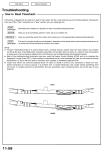
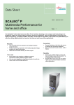
WASHING MACHINE
SERVICE MANUAL
INDEX
TECHNICAL FEATURES
COMPONENT SPECIFICATIONS
ENERGY LABEL
NAME PLATE
FAILURE CODES
AUTO TEST CHART
DETERGENT BOX GROUP WORK PRINCIPLE
CHILD LOCK MANUAL
AUTOTEST MANUAL
2
Component specifications
DOOR LOCK
Door lock is activated at the beginning of the program in
order to prevent the door from opening. It can be
unlocked approximately after 2 minutes of the program
end. This time delay is caused by the PTC which is
assambled in the door lock.
Figure 1. Door lock
Technical features :
Lock Time (20 °C)
Unlock Time (20 °C)
Nominal voltage
Nominal current
2” – 6”
35” – 75”
250 V
16 (4) A
Checking of component :
Check the resistance value on the component with multimeter as shown in Figure2.
Resistance value on the PTC should be 1000 Ω ±50%.
Figure 2. Checking the component
3
DRAIN PUMP
Drain pump is both a mechanical and elektrical component
which is used to drain water inside the washing machine. It
has an synchronous motor inside. For better performance
maintanance, pump filter should be cleaned regularly.
Figure 3. Drain pump
Technical features :
Nominal voltage
Nominal current
Nominal power
Frequency
Resistor (coil)
Water flow:
Thermal protector
230 V
0.2 A
30 W
50 Hz
170 Ω (±7%)
18 l/min(to 1 m height)
YES
Checking of component :
Check the resistance value on the component with multimeter as shown in Figure 4.
Resistance value should be between 140- 200 Ohm
Figure 4. Checking the component
4
NTC
Component which sends signals to PCB about the water temperature inside
the tub. The Resistance (Ohm) value of the NTC decreases as the
temperature increases.
Figure 5. NTC
Techinal Feature :
Tem (°C) R nom (Ω)
Ω)
-10,00
- 5,00
0,00
5,00
10,00
15,00
20,00
25,00
30,00
35,00
40,00
45,00
50,00
55,00
60,00
65,00
70,00
75,00
80,00
85,00
90,00
95,00
100,00
58.722,00
45.778,00
35.975,00
28.516,00
22.763,00
18.279,00
14.772,00
11.981,00
9.786,00
8.047,00
6.653,00
5.523,00
4.608,00
3.856,00
3.243,00
2.744,00
2.332,00
1.990,00
1.704,00
1.464,00
1.262,00
1.093,00
949,90
R min
(Ω)
Ω)
54.874,00
42.961,00
33.900,00
26.977,00
21.616,00
17.421,00
14.128,00
11.497,00
9.421,00
7.772,00
6.444,00
5.365,00
4.489,00
3.767,00
3.178,00
2.681,00
2.273,00
1.934,00
1.653,00
1.416,00
1.218,00
1.053,00
913,20
R max
(Ω)
Ω)
∆ R (+/- %)
62.570,00
6,60
48.596,00
6,20
38.050,00
5,80
30.055,00
5,40
23.910,00
5,00
19.137,00
4,70
15.417,00
4,40
12.464,00
4,00
10.150,00
3,70
8.322,00
3,40
6.861,00
3,10
5.680,00
2,80
4.726,00
2,60
3.945,00
2,30
3.308,00
2,00
2.808,00
2,30
2.392,00
2,50
2.045,00
2,80
1.755,00
3,00
1.511,00
3,20
1.305,00
3,40
1.133,00
3,70
986,60
3,90
Table 1 .NTC Tempure – Resistance Values
5
Checking of component :
Check the resistance value on the component with multimeter as shown in Figure 6.
Figure 6. Checking the component
6
EMI FILTER
EMI Filter Functions:
1. To adjust the frequency changes to the value of 50-60 Hz
which is the nominal frequency for the components.
2. To prevent harmonic frequency feedback sent by motor ,
resistance to the the network.
Figure 7. EMI Filter
Technical features :
Rated Voltage
Rated Current
Cx
Cy
L
R
250 V
16 A
0,47 µF (±20%)
2 x 25 nF (±20%)
2 x 1 mH (+%50,-%30)
680 kΩ (±10%)
Checking of component :
Check the resistance value on the component with multimeter as shown in Figure 8.
Resistance value on the EMI filter (between L-N polars) should be 680 kohm (±10%).
7
Figure 8. Checking the component
PRESSURE SWITCH
Voltage
Amper
: 250 V
:16 A
Figure 9. Pressure switch
Pressure switch is the component which regulates the water intake according to the water levels set
inside. The component is operated by PCB card. It has four connections : Reset, set, common,
overflow.
Technical features :
The component has three levels. When the component is at reset level, the machine begins to take
water inside. When the component is at set level, the machine stops to take water inside by
communicating with PCB card. The third level, overflow level, is set to prevent taking excessive
water(overflow) into the machine.
The pressure switches that have different water set levels have different water intake values
accordingly.
Checking of component :
1 ) Blow into the pressure switch hose or pressure switch entry. Be sure that you hear the switch click.
2 ) Turn the program adjustment knob rinse mode and let the machine take water in. Be sure that you
hear the switch click or the machine stops to take water inside after a while. (Figure 10.)
Figure 10. Program knob
8
RESISTANCE
Heating element (Resistance) is a component which is
desingned to regulate temperature of water inside the
drum. It has three connections: Phase, notral and ground
connections.
Figure 11. Resistance
Technical features :
Kind of heating
Nominal voltage
Nominal power
Resistance
Thermal fuse
Tubular heating element with NTC – sensor
230 V
1850 W (±5%)
26.96-29.80 Ω
2 – sided
Checking of component :
Check the resistance value on the component with multimeter as shown in Figure 12.
Resistance value should be between 25- 30 Ohm.
Figure 12. Checking the component
9
VALVE
Valve is an electrical and mechanical component which is
designed to take water from the network system into the washine
machine. It is operated by PCB card.
Figure 13. Valve
Technical features :
Nominal voltage
Nominal power
Frequency
Rated flow:
Operating water pressure
220 – 240 V
8 VA
50 Hz
6 1/min (±15%) (for cold inlet)
5.5 1/min (±15%) (for hot inlet)
0.2 – 10 bar
Checking of component :
Check the resistance value on the component with multimeter as shown in Figure 14.
Valve water flow rate should be between 6 - 8 lt/min.
Each valve bobbin resistance values should be between 3 - 4.5 kΩ .
Figure 14. Checking the component
10
MOTOR
The washing machine has an asynchronous
motor. It is controlled by the PCB.
It is essential to check the motor for correct
diagnosis and quick servicing. In the below picture,
socket points on the motor is shown to measure with
multimeter.
Figure 15. Motor
Tacho socket
terminal
Rotor coil
socket
terminal
Stator coil
socket
terminal
Tapped filled
coil socket
terminal
Figure 16. Motor socket terminals
11
Earthing
Tacho and stator (full field-half field) ohm resistance values for the motor types are listed in the below table.
MOTOR
CODE
SUPPLIER
STATOR (FULL
FIELD) (ohm)
TACHO
(ohm)
STATOR (HALF
FIELD) (ohm)
30027193
ANAIMEP
1.87-/+7%
180 -/+10%
20 ºC
30023397
ANAIMEP
1.75-/+7%
180 -/+10%
20 ºC
32002064
ANAIMEP
2.01-/+7%
180 -/+7%
20 ºC
32003425
ANAIMEP
2.01-/+7%
180 -/+7%
20 ºC
32000536
CESET
1.01 -/+7%
68.7-/+7%
20 ºC
32000271
CESET
1.40 -/+7%
68.7-/+7%
32000535
CESET
1.24 -/+7%
68.7-/+7%
32000537
CESET
1.34 -/+7%
68.7-/+7%
32002064
WELLING
2.08 -/+7%
66.6 -/+7%
20 ºC
32003425
WELLING
1.59 -/+7%
66.6 -/+7%
20 ºC
32004572
ACC
1.20 -/+7%
184 -/+10%
32004968
ATB
1.63-/+7%
90 -/+12%
32004969
ATB
1.57-/+7%
90 -/+12%
32004970
ATB
1.57-/+7%
90 -/+12%
0.56 -/+7%
Check the motor tacho terminals on the
motor socket with multimeter as shown in the
picture. For resistance values, refer to the table 1.
12
20 ºC
20 ºC
0.56 -/+7%
0.60 -/+7%
20 ºC
20 ºC
20 ºC
0.80 -/+7%
Table 2. Resistance values for the motor types
Tacho resistance control
TEMPERATURE
20 ºC
20 ºC
Stator Full Field Resistance Control
Check the motor stator terminals on the
motor socket with multimeter as shown in the
picture. For resistance values, refer to the table 1.
Stator Half Field Resistance Control
Check the motor stator terminals on the
motor socket with multimeter as shown in the
picture. For resistance values, refer to the table 1.
Operating the motor manually
In order to check the motor operation, it is operated manually by supplying input electricity.
The motor operation s should be checked by supplying energy for a short time. In the below pictures,
the checking operation is demonstrated.
Connect the rotor coil terminal and stator coil terminal with a conductive wire.
13
-W Tf-
-W0 Tf-
Connect one of the wires on the power cable with other rotor coil terminal.
-W Tf-
-W0 Tf-
Connect the other wire on the power cable with other stator coil terminal.
-W Tf-
-W0 Tf-
Note: The motor must be earthed by the
earth cable as shown in the picture.
14
Plug the power cable. (220 V 50 Hz). After
checking the motor operation, unplug the power
cable soonest.
(Please do not plug the power cable more than
15 seconds. )
15
ENERGY LABEL
LOGO:XXXXXX
MODEL:XXXXX
ENERGY PERFORMANCE
A
ENERGY CONSUMPTION
5
6
7
7,5
KG
KG
KG
KG
: 0,95 kWh/program
: 1,14 kWh/program
: 1,33 kWh/program
: 1,42 kWh/program
WASHING PERFORMANCE
A
SPINNING PERFORMANCE
600 RPM
800 RPM
1000 RPM
1200 RPM
1400 RPM
1600 RPM
:E
:D
:C
:B
:B
:A
CAPACITY
5 KG
6 KG
7 KG
7,5 KG
WATER CONSUMPTION
5 KG
6 KG
7 KG
7,5 KG
:
:
:
:
43 lt
49 lt
62 lt
63 lt
16
NAME PLATE
0000
17
SERVICE INDEX
NUMBER
Failure Codes
FAILURE CODE 1
A- Failure indicator situations
18
B- Error flowcharts
19
FAILURE CODE 2
B- Failure indicator situations
20
B- Error flowcharts
21
FAILURE CODE 3
C- Failure indicator situations
22
B- Error flowcharts
23
FAILURE CODE 4
D- Failure indicator situations
4
24
B- Error flowcharts
25
FAILURE CODE 5
E- Failure indicator situations
26
B- Error flowcharts
27
FAILURE CODE 6
F- Failure indicator situations
28
B- Error flowcharts
29
FAILURE CODE 7
G- Failure indicator situations
30
B- Error flowcharts
31
FAILURE CODE 8
H- Failure indicator situations
32
B- Error flowcharts
33
FAILURE CODE 9
I- Failure indicator situations
34
B- Error flowcharts
NOTE :
FIX ON
FLASH-BLINK
35
36
Auto Test Chart
DETERGENT BOX GROUP WORK PRINCIPLE
MAIN
SOFTENER
VALVE 1
PREWASH
VALVE 2
PREWASH = WATER ENTRY VALVE 1
MAIN
= WATER ENTRY VALVE 2
SOFTENER = WATER ENTRY VALVE 1 + VALVE 2
37
CHILD LOCK MANUAL
Press the start-end and second function button for 3-4 seconds to activate child lock.
38
AUTOTEST MANUAL
1. Turn the program knob to third program.
2. Press the first function button.
39
3. While pressing the first function button, turn the program knob to second program.
4. Release the function button. The button light will be on.
40
5. Press the first function button again.
6. While pressing the first function button, turn the program knob to first program.
Release the function button and the autotest starts.
41
7. When the first function button light flashes, press the button again. Autotest will enter
the second phase.
42