1
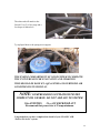
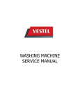
specializing in “AIR CONDITIONING, PARTS AND SYSTEMS” for your classic
vehicle
“PERFECT FIT SERIES”
IN-DASH
HEAT/ COOL/ DEFROST
1969-70 MUSTANG
CONTROL & OPERATING INSTRUCTIONS
The controls on your new “Perfect Fit” system. Offers complete comfort capabilities in
virtually every driving condition. This includes Temperature control in all of the modes.
This system also provides the ability to blend the air between Heat, and Defrost modes.
MODE LEVER
FAN SWITCH
TEMPERATURE LEVER
THE PICTURE YOU SEE ABOVE SHOWS THE CONTROLS IN THE FLOOR
MODE. THIS MEANS THAT THE AIR WILL BE DISTRIBUTED THROUGH THE
FLOOR OUTLETS. THIS ALSO HAS THE TEMPERATURE LEVER IN THE COLD
POSITION. WITH THE CONTROLS IN THIS POSITION YOU WILL GET THE AIR
THROUGH THE FLOOR OUTLETS AT ROOM TEMPERATURE.
1
CAUTION: ALL OF THE OUTSIDE VENTS MUST BE CLOSED WHEN THE
SYSTEM IS IN THE A/C MODE. THIS WILL ALLOW THE A/C SYSTEM TO
FUCTION AT ITS MAXIMUM PERFORMANCE LEVEL.
THE FOLLOWING SUMMARY WILL DESCRIBE EACH OF THE CONTROL
LEVERS FUNCTION.
FAN SPEED SWITCH: There are 3 speeds plus Off. When the switch is in the off
position it will disconnect the 12V power to the Blower Motor and the A/C Clutch. This
will shut down the entire system. When the switch is moved to any of the blower speeds
1,2 or 3 there is 12V supplied to the Micro-Switch which is mounted on the defrost air
housing.
FLOOR / FACE / DEFROST MODE: When the top lever is pulled all the way to
the LEFT, it will direct the air to the floor ducts. When the lever is moved into the
CENTER position the air is directed to the Dash Louvers. When the lever is pushed to the
far Right, the air will be directed onto the defrost outlets. When the lever is in the Defrost
position the A/C Compressor is activated and provides Dehumidification.
TEMPERATURE CONTROL: The temperature lever as shown is in the
COLDEST temperature position. As the lever is pushed to the right the temperature of
the discharged air will rise to the HOTTEST point.
Note: The temperature lever will function in any of the modes.
AIR CONDITIONING MODE: The picture shows the controls in the Floor Mode
(air-flow out the floor outlets).
When Air Conditioning is required the compressor clutch must be activated. This is
accomplished when the top lever is in the Center position. When the compressor is
activated the Temperature Lever will control the air from maximum cold through
maximum heat.
2
specializing in “AIR CONDITIONING, PARTS AND SYSTEMS” for your classic
vehicle
INSTALLATION INSTRUCTIONS
1969-70 MUSTANG
Congratulations! ! You have just purchased the highest quality, best performing A/C system ever
designed for you Classic Car. To obtain the high level of performance and dependability our
systems are known for, pay close attention to the following instructions.
Before beginning the installation check the box for the correct components.
Evaporator
Face Duct Assembly
Defrost / Heat Duct Assembly
Inlet Air Block Off Assembly
Firewall Block Off Assembly
Flex Hose 2 ½”dia. (1) 2’, (1) 3’, (1) 4’
Flex Hose 2” dia. (1) 2’, (1) 3’
Sack Kit Hardware
Sack Kit Control
IMPORTANT INFORMATION
1.
2.
3.
4.
5.
6.
7.
8.
9.
Before starting, read the instructions carefully and follow proper sequence.
Check condition of engine mounts. Excessive engine movement can damage
hoses to A/C, heater, radiator, transcooler, and power steering systems.
Before starting, check vehicle interior electrical functions. i.e. interior lights,
radio, horn, etc. When ready to start installation, disconnect battery.
Fittings. Use one or two drops of lubricant on O’rings, threads and rear of bump
for O’ring where female nut rides. Do not use thread tape or sealants.
Always use two wrenches to tighten fittings. Try holding in one hand while
squeezing together while other hand holds fitting in position.
Shaft seals in a small percentage of compressors will require as much as 3-4
hours run time to become leak free.
Compressors supplied in our complete systems are filled with proper amount of
oil.
Compressor requires technician to hand turn 15-20 revolutions before and after
charging with liquid from a charging station before running system.
Compressors with damaged reed valves cannot be warranted.
Should you have any technical questions, or are suspect of missing, or defective
parts, call us immediately. Our knowledgeable staff will be glad to assist you.
YOU CAN NOW BEGIN THE INSTALLATION
3
Remove Glove box, Passenger
Fascia, and Padded Dash Cover
Retain original hardware.
See below for screw locations.
GLOVE BOX
DASH FASCIA
(2) SCREWS
Remove radio mounting bracket and the original
control head.
Following steps are required to remove the radio
mounting bracket.
Remove the radio knobs and (2) screws above the
radio. Carefully pull the radio bezel away from the
dash. The bottom of the bezel inserts into clips.
Remove the (5) screws as shown.
The (2) screws on the left and right are used
to attach the plastic trim sections.
Remove and retain the original hardware.
4
Removal of the control head requires
disconnection of the Mode Control cable.
This is located below the defrost duct.
The Temperature Control cable is located on top of
the heater, behind glove box opening.
Located behind glove box opening and on front of the
heater is a resistor assembly. Disconnect wires and cut
off the single wire to the blower motor.
CUT HERE
Remove the Defrost Air
Duct along the body
flange.
Remove the (3) nuts.
Retain original hardware.
(3) STUDS HOLDING DEFROST
Set aside for modification.
5
Locate blower motor on the firewall (Passenger
Side) in engine compartment. Remove 5 nuts around
blower. Also disconnect electrical connector from
the blower motor.
Cut wires at grommet in firewall.
DRAIN COOLANT FROM RADIATOR.
Cut Heater hoses approximately 1” from firewall.
Remove the screw that is located just in front of the
air inlet to the heater.
Retain original hardware.
Picture to the right shows the heat
distribution duct attached to bottom of the
heater. This picture shows heater assembly
outside of the vehicle. The heat duct must be
removed while in the vehicle.
PUSH PIN
Remove push pins.
Locate on the right side of
lower dash. (2) bolts. (1)
inside glove box opening and
into the kick panel. (1) under
glove box opening and into a
bracket.
Remove and retain hardware.
6
Pull lower edge of the dash towards the rear of car to
allow clearance for the heater assembly.
Remove complete Heater Assembly and discard.
Located on page 25 of instructions is
a template. Carefully cut out the
template and place it over the hole in
firewall behind glove box.
Drill (1) hole 5/16” dia., and
(1) hole 3/4” dia..
SEE NOTE BELOW BEFORE
DRILLING.
Caution: on the engine side of firewall there is a brake line. Do
not drill through. It may be necessary to carefully relocate this
line.
5/8” Dia. hole.
Brake line
7
Locate original wiring harness that was connected to
original blower switch. From the plug cut the YELLOW
wire and attach a ¼” insulated male spade connector.
All modifications to the vehicle are complete. You can now begin
installing your Classic Air “Perfect Fit Series” system.
Locate the original control head.
Remove original blower switch and the mode
control cables. Discard switch, switch knob and
the cables. Retain original hardware.
In the control sack kit you will find the control
switch mounting bracket. Attach bracket using
original screw that holds rear section of the
control head to the front section.
Locate the new Blower Switch, and (2) #6 x 3/8”
Pan Head Screws. Attach switch as shown.
8
Locate knob in control sack kit and install over
switch shaft.
Locate in the control sack kit (2) cables.
Longest one is for the Temperature lever .
Attach with (1) #8 x 1/2” pan head phillips
screw and the cable clamp provided.
Short cable is attached to the mode control
lever. Hold cable over edge of the control head
as shown below. Mark and drill a 1/8” Dia.
hole and attach the cable with (1) #10 x 5/8”
pan head phillips screw.
CABLE CLAMP
Drill 1/8” Dia hole.
Set aside for later installation.
9
Locate the Inlet Block off Plate.
Located above glove box opening place
block off plate over the hole. Attach with
(2) #10 x ¾ “ hex washer head tek
screws.
Locate Evaporator. Slide evaporator up into place behind the glove box opening.
From engine compartment attach evaporator using ¼ - 20 x
5/8 hex head screw with ¼” washer through the 5/16” Dia.
hole previously drilled.
Behind glove box opening attach the
blower support bracket as shown.
Attach with the original screw as shown.
Behind original screw you will find an
additional hole in the support bracket.
Install a #10 x ¾” hex washer head tek
screw through this hole and into the
cowling.
10
Locate in the hardware sack kit the evaporator
Support Bracket.
Attach bottom end of the bracket to the (2) 1/8” Dia.
holes in front of the evaporator using (2) #10 x 5/8
pan head Philips screws.as shown.
Holding the unit level attach top end to the cowling
using (1) #10 x ¾: hex head tek screw.
Tighten all screws.
Locate the Firewall Block Off Plate.
On engine side of firewall attach over the hookup
tubes from evaporator using (2) #10 x 5/8 “ hex
washer head Tek screws.
Locate insulation tape provided and seal around the
hookup tubes as shown.
Water Valve / (3) hose clamps.
Locate the Water Valve and (3) worm gear clamps.
Supply line from the engine is attached to the lower heater hookup tube. Cut 6” off the end of
return line and install the water valve using (3) worn gear clamps as shown above.
See Techinal Data sheet on page 24.
Note: It is recommended that you replace heater hoses from the engine to the hookup tubes.
Locate the ½” Dia. x 6” long piece of clear
drain tube.
Insert through 11/16” Dia. hole previously
drilled and attach over drain nipple on the
evaporator. Using the insulation tape seal
around tube.
11
Locate the Defrost / Heat Duct Assembly.
Attach to evaporator using (2) #10 x 5/8 pan
head Philips screws. Be sure that the S-clips
are pressed over the rear flange. This helps
secure the duct assembly.
Locate 2” dia flex hose (1) piece 2’ long and
attach it to right outlet as shown.
Find (1) piece of 2” dia. flex hose 3’ long and
attach it to left outlet. Route hose down and
behind the micro switch assembly.
BLUE WIRE FROM BLOWER
SWITCH
BLUE WIRE TO THE
THERMOSTAT
Locate wire harness from the evaporator electric actuator and attach to the (2) micro switches.
Refer to the wiring diagram on next page.
Attach Wire Harness supplied in unit to the blower switch. Route harness through the control
opening. Attach wire harness to left micro-switch on Defrost Duct assembly. Route harness
across top of the unit and hookup the resistor, and blower motor. Route the blue clutch wire over
evaporator and out through hole in the firewall block off plate.
12
13
Secure ground from the electronic actuator and the blower
motor using (2) #10 x ¾“ hex washer head Tek screw.
REFER TO THE WIRING DRAWING ON PAGE 11 FOR
PROPER CONNECTIONS.
Connect power wire (yellow / from the
original harness) to Red / White stripe wire
from the new harness supplied.
Route longest of (2) cables that were
attached to the control head, around and
over top of radio and then back and behind
evaporator assembly and out through upper
hole that the original heater hose was
inserted through. Attach this cable to the
water valve.
Set control lever in the Cold position and
be sure that the water valve is closed.
Locate in the hardware sack kit (2) 1” dia.
cap plugs. Cut a slot in one of the plugs and
slide it over the temperature cable. Push on
over heater hole. Install second cap plug
over the lower hole.
14
Route shortest of (2) cables and attach to the defrost / heat duct.
Insert cable into second hole from the bottom.
Attach using (1) #10 x 5/8” pan head philips screw.
Reinstall controls into instrument panel using the
original hardware.
Reinstall radio mounting bracket, and bezel using
original hardware.
Locate the Face Duct
Assembly. Attach to the
evaporator. There are s-clips
on the back edge of the face
duct. Make sure that they
slide over the flange on the
evaporator.
(2) #10 x 5/8” PAN HEAD
SCREW
Attach using (2) #10 x 5/8”
pan head phillips screws.
15
Locate Defrost Air Duct lay on
table and mark a line 4” from the
top lip as shown.
Cut off lower part of the duct
And discard.
Locate in the hardware sack kit (1) piece of ¼” x ½” open
cell seal. Attach to cut edge of the original defrost duct.
Locate the Defrost Hose Adaptor supplied. Attach over
end of the defrost duct using (4) #10 x 5/8” pan head
screws.
Reinstall defrost duct assembly
using original hardware.
Locate (2) 2” dia flex hose
attached to the Defrost
assembly. Secure with (2) #10 x
5/8” pan head screws.
16
Route over the face duct and attach to the hose adaptors as shown.
Locate the 2 ½” dia flex hose (1) piece 3’ long
and attach it to outlet behind the left defrost
flex hose.
3’ FLEX HOSE
Route across to the left side of the steering
column for the drivers louver assembly.
Locate 2 ½” dia. flex hose and (1) piece 2’ long and (1) piece 4’ long.
Attach 2’ piece to the left hose adaptor as shown.
Attach 4’ piece to the right hose adaptor and route across top of glove box and
down the right side and attach to passenger side louver assembly.
17
Locate the Template on page 27 of instructions. Carefully cut Template as described.
Carefully tape template from the bottom
edge and center of the Padded Dash.
Cut opening to the exact size as the
template.
CAUTION: PADDED DASH IS VERY DELICATE. ALWAYS CUT THE HOLE
SMALLER THAN REQUIRED AND THEN DO A FINISHING CUT.
BACK SIDE OF PADDED DASH
Place the Dash Panel on its face and trim the metal part
along the sides. Bend metal down to gain clearance for
the louver.
TRIM METAL AND BEND
DOWN. AS SHOWN
BENT METAL
18
Locate in the Hardware Sack Kit the Center
Louver. Insert louver through the cut hole.
Using a straight edge carefully insert between
the louver and the dash pad and push the pad
out even with the louver bezel.
Reinstall Padded Dash using
original hardware.
Attach 2’ piece of hose to the louver
as shown.
CENTER FLEX HOSE
Locate original Glove Box Assembly.
Modify back edge of the box for clearance on the
evaporator.
Cut 1” horizontal and 1” vertical across the entire
back of box.
Reinstall Glove box and Passenger Fascia using
original hardware.
19
Located on page 29 & 31 of instructions the
driver and passenger louver template.
On drivers side follow instructions on template
and attach to dash as shown. Cut center using
template as a guide.
On passengers side follow instructions on
template and attach to dash as shown. Cut
center using template as a guide
Locate in hardware sack kit (2) of the
Louver Assemblies.
Attach assembly through passenger side
hole and screw hose adaptor onto louver.
Attach 4’ piece of flex hose to rear of
housing and over hose adaptor.
Attach assembly through drivers side hole
and screw hose adaptor onto louver.
Attach 3’ piece of flex hose to rear of
housing and over hose adaptor.
Caution: Carefully check under the Instrument Panel for all cables, electrical
harness, or Flex Ducting that might interfere with the safe operation of the vehicle.
Make sure that you cycle the Windshield Wipers to insure proper clearance of
mechanism.
20
Locate in the Condenser kit the Drier, Drier Mounting bracket, pressure switch kit,
Liquid Tube, (2) #10 tek screws, and (2) #6 o-rings.
TOWER SUPPORT BRACE
SPRING
TOWER
To locate the drier use the
liquid tube from firewall to
the spring tower as shown.
Attach using (2) #10x ¾”
tek screws.
(2) #10
TEK
SCREWS
Install tube using the (2) #6
o-rings and few drops of
mineral oil.
Attach the pressure switch to the top of the drier using a
few drops of mineral oil.
INSTALL COMPRESSOR AND MOUNTING HARDWARE USING INSTRUCTIONS
SUPPLIED WITH KIT. BE SURE THAT COMPRESSOR ON V8 ENGINE IS
INSTALLED WITH FITTINGS 90 Deg. FACING DRIVERS SIDE FENDER
Remove the following components: Center Hood Latch Assembly, and (2) horns. Set
aside for reinstallation.
21
Located on the drivers side radiator support is a
knockout in the sheet metal. There are (2) dimples these
are the locators for the hole cutout.
DIMPLES
Using a 1 3/8” dia. hole saw cut (2) holes using
the dimples as center of hole.
Using a hammer knockout the center as shown.
Debur hole smooth. Paint edges to prevent
corrosion.
Locate the Condenser Coil, discharge tube assembly, and liquid tube assembly.
Attach liquid tube to condenser using (1) #6 o-ring and a few drops of mineral oil.
Attach discharge tube to condenser using (1) #8 o-ring and a few drops of mineral oil.
Locate (2) top and (2) lower
condenser mounting brackets,
and (8) #10 x 3/8” HWH
screws.
Loosely attach brackets to
condenser as shown.
22
Locate the tube support clamp assembly
and attach to the tubes as shown.
Slide Condenser
Assembly into place as
shown. Insert the tube
through the hole
previously cut.
The upper attachment brackets
should line up with holes already
in radiator support.
Attach using (2) #14 x ¾” tek
washer head screws.
Locate #10 x ¾” tek screws.
The lower brackets attach to the
radiator support using these
screws.
Tighten the (8) # 10 screws on the
condenser.
23
Locate the long Liquid Hose. This hose has a Straight and a 45
Degree Fitting pre crimped into position.
Loosely attach the straight end of the hose to the liquid tube, the 45
Degree end should be attached to the drier mounted on the spring
tower. Attach using (2) #6 o-rings and a few drops of mineral oil.
Tighten all fittings.
VEHICLES WITH V8 ENGINES:
Attach the disharge hose assembly to condenser and
then to compressor.
Attach using (2) #8 o-ring using a few drops of
mineral oil.
Locate the Suction Hose. The hose has (2) 90 Degree
fittings pre-attached in the correct position. One of
the ends has a service fitting, this should be attached
to the compressor.
Suction hose
Connector to clutch
The other end will attach to the suction tube coming
from the evaporator assembly. Check for o-rings
and apply oil before attachment.
Tighten all fittings.
24
Locate female bullet connector that is supplied
with the Hi-Low pressure switch.
Cut one of the white wires from the pressure
switch. Attach bullet connector to this wire and
plug into the compressor clutch wire.
As shown route the long white wire from the
pressure switch along the suction hose and connect
to the clutch wire that was inserted through
firewall.
Carefully route liquid
and suction hoses
Ty-rap suction and liquid hose to the spring tower
support.
VEHICLES WITH 6 CYL. ENGINES.
Attach the disharge
hose assembly to
condenser and then to
compressor.
Attach using (2) #8 oring using a few drops
of mineral oil.
Locate the Suction Hose. Attach hose with 90
Degree fitting with service port to the
compressor.
25
The other end will attach to the
firewall. Use (2) #10 o-rings and a
few drops of mineral oil.
Ty-rap liquid hose to the spring tower support.
THE ENGINE COMPARTMENT OF YOUR SYSTEM IS COMPLETE.
THE UNIT IS READY FOR EVACUATION AND CHARGING.
THIS SHOULD BE DONE BY A QUALIFIED AND CERTIFIED AIR
CONDITIONING TECHNICIAN.
NOTE: COMPRESSOR IS SUPPLIED WITH THE
CORRECT OIL CHARGE. DO NOT ADD OIL TO SYSTEM.
134a SYSTEMS
24 oz OF REFRIGERANT
Recommend that power fuse is 25 amp minimum.
Congratulations you have completed the install of your CLASSIC AIR
“Perfect Fit Series” system.
26
IMPORTANT
CAUTION: WATER VALVE MUST BE INSTALLED PER
THE INSTRUCTIONS.
Classic Auto Air has done extensive testing on the correct method to install the water valve in order to get a
repeatable and progressive temperature control.
Locate the bottom connection from the evaporator/heater unit off of the firewall and attach a 6” piece of
5/8” dia. heater hose with the supplied hose clamp. Next attach the inlet side of the water valve using
another supplied hose clamp, (make sure the arrow on the water valve points toward the engine) Attach a
heater hose from the outlet side of the water valve and route to the connection on the water pump.
NOTE: WATER VALVE = WATER PUMP
FROM HEATER CORE
TO WATER PUMP
COOLANT FLOW
CAUTION: WATER VALVE MUST BE INSTALLED ON HEATER LINE ROUTED TO
WATER PUMP.
NOTE: COMPRESSOR PURCHASED WITH KIT IS
SUPPLIED WITH THE CORRECT OIL CHARGE. DO NOT
ADD OIL TO SYSTEM.
134A SYSTEMS
24 oz OF REFRIGERANT
Recommend that power fuse is 25amp minimum
27