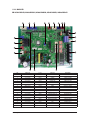
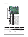
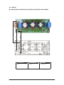
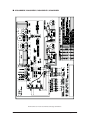
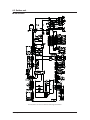
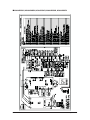
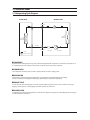
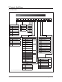
1
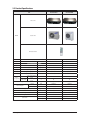
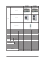
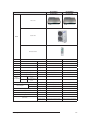
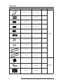
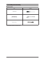
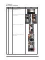
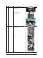
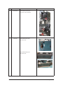
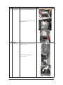
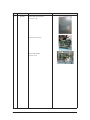
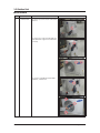
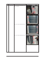
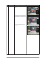
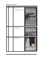
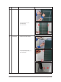
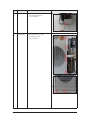
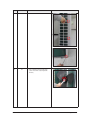
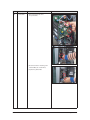
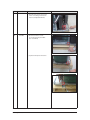
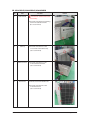
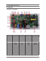
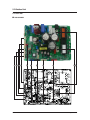
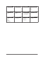
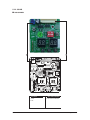
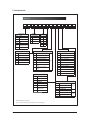
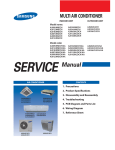
SYSTEM AIR CONDITIONER
MA DUCT SERIES
Model :
AIR CONDITIONER
INDOOR UNIT
OUTDOOR UNIT
AC018JNHDCH/AA
AC024JNHDCH/AA
AC030JNHDCH/AA
AC036JNHDCH/AA
AC042JNHDCH/AA
AC048JNHDCH/AA
AC018JXADCH/AA
AC024JXADCH/AA
AC030JXADCH/AA
AC036JXADCH/AA
AC042JXADCH/AA
AC048JXADCH/AA
CONTENTS
1. Precautions
2. Product Specifications
AC018JNHDCH/AA
AC024JNHDCH/AA
AC030JNHDCH/AA
AC036JNHDCH/AA
AC042JNHDCH/AA
AC048JNHDCH/AA
3. Disassembly and Reassembly
4. Troubleshooting
5. PCB Diagram
AC018JXADCH/AA
6. Wiring Diagram
AC036JXADCH/AA
AC042JXADCH/AA
AC048JXADCH/AA
AC024JXADCH/AA
AC030JXADCH/AA
7. Reference Sheet
Contents
11. Precautions ........................................................................................................................................ 1-1
1-1 Precautions for the Service .............................................................................................................
1-1
1-2 Precautions for the Static Electricity and PL ................................................................................
1-1
1-3 Precautions for the Safety ...............................................................................................................
1-1
1-4 Others ..................................................................................................................................................
1-1
12. Product Specifications ............................................................................................................... 2-1
2-1 The Feature of Product ....................................................................................................................
2-1
2-2 Product Specifications .....................................................................................................................
2-2
2-3 Accessory
2-5
...........................................................................................................................................
3. Disassembly and Reassembly
..............................................................................................
3-1
3-1 Indoor Unit .........................................................................................................................................
3-2
3-2 Outdoor Unit
.....................................................................................................................................
4. Trouble shooting
3-10
...........................................................................................................................
4-1
4-1 Indoor Display Error and Check Method .....................................................................................
4-1
4-2 Troubleshooting by symptoms
4-5
.....................................................................................................
4-3 Setting Option Setup Method ........................................................................................................ 4-13
4-4 Setting an indoor unit address and installation option ............................................................ 4-14
4-5 Items to be checked first ................................................................................................................ 4-18
5. PCB Diagram and Parts list ...................................................................................................... 5-1
5-1 Indoor Unit
........................................................................................................................................
5-2 Outdoor Unit
.....................................................................................................................................
6. Wiring Diagram
5-1
5-4
.............................................................................................................................
6-1
.......................................................................................................................................
6-1
6-2 Outdoor Unit ....................................................................................................................................
6-3
6-1 Indoor Unit
7. Reference Sheet
.............................................................................................................................
7-1 Refrigerating Cycle Diagram
7-1
..........................................................................................................
7-1
7-2 Index for Model Name .....................................................................................................................
7-2
1. Precautions
1-1 Precautions for the Service
O Use the standard parts when replacing the electric parts.
– Confirm the model name, rated voltage, rated current of the electric parts.
O Repair the disconnection of HARNESS securely when repairing the break down.
– If there is any connection error, it causes an abnormal noise and incorrect operation.
O In case that you assemble or disassemble the products with laying it on the side, do work on the work cloth.
– If not, the exterior of products can be scratched.
O Remove dust and foreign materials from harness, connection part, and inspection part thoroughly when repairing the break down.
– It protects the danger of fire such as tracking and short.
O Tighten tightly the service valve of outdoor unit and the cap of charging valve with a monkey spanner.
O Check the assembly status of parts after repairing the break down.
– It should be same as the status before repairing.
1-2 Precautions for the Static Electricity and PL
O As the PCB power terminal has a weakness for the static electricity, pay attention to it during the repair and measurement.
– Work with insulation gloves during the repair and measurement of PCB.
O Check the distance between the product and the other electronic appliances such as TV, video, and audio. It should be over 2m.
– If not, it causes a bad picture quality or a noise.
O Repairing the products by consumer should be strictly prohibited.
– There is a danger of electric shock or fire due to incorrect disassembly.
1-3 Precautions for the Safety
O Do not pull any electric wires and do not touch an auxiliary power switch with a wet hand.
– There is a danger of electric shock or fire.
O In case any wire or power plug has been damaged, replace it to eliminate any possible danger.
O Do not bend the power cord by force and do not put any heavy object on the power cord.
– There is a danger of electric shock or fire.
O Do not use multi socket.
– There is a danger of electric shock or fire.
O Ground the product if necessary.
– Be sure to ground the product if there is any danger of electric leakage due to water or moisture.
O Be sure to turn off the auxiliary power switch or pull out the power plug during replacement or repair of electric parts.
– There is a danger of electric shock.
O In case the product will not be in use for a long time, the battery of remote control should be kept separately.
– Leakage of inside fluid can cause break down of remote control.
1-4 Others
O
O
O
O
O
Never store or load the air conditioner upside down or sideways to prevent the damage to the compressor.
Young children or infirm persons should be always supervised when they use the air conditioner.
Max current is measured according to IEC standard for safety.
Current is measured according to ISO standard for energy efficiency.
When installing, make sure there is no leakage. When recovering the refrigerant, ground the compressor first before removing the
connection pipe. If the refrigerant pipe is not properly connected and the compressor works with the service valve open, the pipe
inhales the air and it makes the pressure inside of the refrigerant cycle abnormally high. It may cause explosion and injury.
O Pump Down Procedure (When removing the product)
- Turn on the air conditioner and select Cool mode to run the compressor for 3 minutes.
- Release the valve caps on High and Low pressure side.
- Use L wrench to close the valve on the high pressure side.
- Approximately 2 minutes after, close the valve on the low pressure side.
- Stop operation of the air conditioner.
- Disconnect the pipes.
Samsung Electronics
1-1
2. Product Specifications
2-1 The Feature of Product
■ Built-in Duct Type
After installed, the air conditioner can be harmonized with a room interior.
■ High Performance & Energy Saving
With the advanced BLDC inverter technology, it makes a room cool with highly energy saving and arises the efficiency of air
conditioner.
■ Long Piping (Length & Height)
It can give the benefit to the installers and aries the reliability of the air conditioner.
■ Long Ambient Operation (In Low Temperature)
It can arise the reliability and the capacity of the air conditioner, especially operated in low temperature.
■ Eco-friendly Product (Lead-Free, RoHS, WEEE)
2-1
Samsung Electronics
2-2 Product Specifications
ITEM
AC018JNHDCH
AC018JXADCH
AC024JN4DCH
AC024JXADCH
Indoor Unit
Outdoor Unit
IMAGE
Remote Controller
Power
Product
1Φ, 208-230V/60Hz
1Φ, 208-230V/60Hz
mm
1150*320*480
1150*320*480
LxHxD
mm
880*638*310
940*998*330
Product
kg(Net)
43.0
43.0
Indoor
LxHxD
Outdoor
Indoor
Outdoor
Product
kg(Net)
45.0
64.5
Capacity
Cooling/Heating(ISO)
Btu/h
18,000/20,000
24,000/27,000
Power input
Cooling/Heating (ISO)
W
1,605/1,725
1,985/2,350
Operation current
Cooling/Heating (ISO)
A
7.4/8.0
9.2/10.8
A
40
44
A
58
60
g
1300(charged for 7.5m)
2100(charged for 7.5m)
Liquid
mm
1/4"(6.35)
1/4"(6.35)
Gas
mm
1/2"(12.7)
5/8"(15.88)
In case of strongest air
Indoor unit
blow
Noise
(Cooling/Heating)
In case of strongest air
Outdoor unit
blow
Refrigerant (R410A)
Connecting Pipe
Additional Refrigerant (R410A)
g/m
10
10
Standard
m
7.5
7.5
Extension length(Total)
m
30
50
Extension length(Elevation)
m
20
30
Product Option
01C0EC-1C8424-27343B-370005
01C0EC-1C747C-274750-370005
Installation Option
020000-120000-200000-300000
020000-120000-200000-300000
Option Code
Samsung Electronics
2-2
ITEM
AC030JNHDCH
AC030JXADCH
AC036JNHDCH
AC036JXADCH
1Φ, 208-230V/60Hz
1Φ, 208-230V/60Hz
Indoor Unit
Outdoor Unit
IMAGE
Remote Controller
Power
Product
Indoor
LxHxD
mm
1200*360*650
1200*360*650
Outdoor
LxHxD
mm
940*998*330
940*1210*330
Indoor
Product
kg(Net)
58.0
58.0
Outdoor
Product
kg(Net)
70.0
88.0
Capacity
Cooling/Heating(ISO)
Btu/h
30,000/32,000
36,000/40,000
Power input
Cooling/Heating (ISO)
W
2,700/2,660
3,000/3,300
Operation current
Cooling/Heating (ISO)
A
12.0/12.0
13.3/14.3
A
44
46
A
60
60
In case of strongest air
Indoor unit
blow
Noise
(Cooling/Heating)
In case of strongest air
Outdoor unit
blow
Refrigerant (R410A)
Liquid
g
2600(charged for 7.5m)
2800(charged for 7.5m)
mm
3/8"(9.52)
3/8"(9.52)
Connecting Pipe
Gas
mm
5/8"(15.88)
5/8"(15.88)
g/m
22
33
Standard
m
7.5
7.5
Extension length(Total)
m
50
75
Additional Refrigerant (R410A)
Extension length(Elevation)
m
30
30
Product Option
0100EC-1A55D4-275A64-370005
0100EC-1A5902-276470-370005
Installation Option
020000-120000-200000-300000
020000-120000-200000-300000
Option Code
2-3
Samsung Electronics
ITEM
AC042JNHDCH
AC042JXADCH
AC048JNHDCH
AC048JXADCH
1Φ, 208-230V/60Hz
1Φ, 208-230V/60Hz
Indoor Unit
Outdoor Unit
IMAGE
Remote Controller
Power
Product
Indoor
LxHxD
mm
1200*360*650
1200*360*650
Outdoor
LxHxD
mm
940*1210*330
940*1210*330
Indoor
Product
kg(Net)
58.0
58.0
Outdoor
Product
kg(Net)
88.0
88.0
Capacity
Cooling/Heating(ISO)
Btu/h
42,000/47,000
48,000/53,000
Power input
Cooling/Heating (ISO)
W
4,000/3,980
4,950/5,050
Operation current
Cooling/Heating (ISO)
A
16.4/17.3
21.5/20.0
A
48
50
A
62
62
In case of strongest air
Indoor unit
blow
Noise
(Cooling/Heating)
In case of strongest air
Outdoor unit
blow
Refrigerant (R410A)
Liquid
g
2800(charged for 7.5m)
2800(charged for 7.5m)
mm
3/8"(9.52)
3/8"(9.52)
Connecting Pipe
Gas
mm
5/8"(15.88)
5/8"(15.88)
g/m
33
33
Standard
m
7.5
7.5
Extension length(Total)
m
75
75
30
30
Additional Refrigerant (R410A)
Extension length(Elevation)
m
Product Option
0100EC-1A194D-277D8C-370005 0100EC-1A1A81-278CA0-370005
Option Code
Installation Option
Samsung Electronics
020000-120000-200000-300000
020000-120000-200000-300000
2-3
2-4
2-3 Accessory
Item
Descriptions
Code-No.
Q'TY
Installation&Owner's Manual
DB68-05395A
1
Insulation
DB62-04318S
1
Insu DRAIN HOSE
DB62-11028A
1/1/1
INSU HOSE D
DB62-11028E
1/1
INSU TUBE OUT
DB62-11028F
1/1
Remark
TIONS
OWNER'S INSTRUC
INSTRUCCIONES
MANUAL DE
PER L'USOS
ISTRUZIONIINSTRU‚ÍE
MANUAL DE
TION
MANUEL D'UTILISAISUNG
GEBRAUCHSANWE
Air ConditionerSplit
Splut-type Room
domĿstico sistema
ad unitˆ Separate
Aire acondicionado
d'aria per ambienti
Split
Condizionatorede ar condicionado tipo
Aparelho
type sĿparĿ
Climatiseur de
Geteilte raumklimaanlage
Essential Offer
(Indoor Unit)
2-5
2-4
ASSY DRAIN HOSE JOINT
DB67-01191A
1
Ass'y Drain Hose Joint
DB90-06701A
1
GROMMET-HANGER
DB63-00237A
8
FILTER-PRE
DB63-01299B
1
FILTER-PRE
DB63-01299A
1
Cap Drain
DB63-10355C
3
Drain Plug
DB67-00806A
1
Rubber Leg
DB73-20134A
4
Essential Offer
(Outdoor Unit)
Samsung Electronics
3. Disassembly and Reassembly
■ Necessary Tools
Item
Remarks
+SCREW DRIVER
Adjustable Wrench
(8mm, 10mm, 13mm)
M6, M8 Hex Wrench
Disassemble should be worked in pairs.
Samsung Electronics
3-1
3-1 Indoor unit
■ AC018JNHDCH / AC024JNHDCH
No
Parts
1
Assy fan parts
Procedure
Remark
1)Disassemble the Cabinet-blower
-Unscrew 19 screws
2)Disassemble the Partition-front from Partition
- Unscrew 8 screws
3)Rotate the assy fan parts in CCW direction.
4)Pull out the assy fan parts after hang at the
edge of cabinet
3-2
Samsung Electronics
No
Parts
2
Drain Pan
Procedure
Remark
1)Disassemble the cabinet-drain
-Unscrew 7 screws
2)Disassemble the Drain pan
- Unscrew 4 screws.
3
Drain pump
1)Disassemble the drain pump kit from the set.
- Unscrew 2 screws
2)Disassemble the drian pump case.
- Unscrew 4 screws.
Samsung Electronics
3-3
No
Parts
Procedure
3
Drain pump
3)Disassemble the drian pump.
- Unscrew 2 screws and cabel tie.
4
Evaporator
1)Disassemble the Cover-pipe
-Unscrew 5 screws
Remark
2)Disassemble the Evaporator
-Unscrew 4 screws
3-4
Samsung Electronics
No
Parts
5
Main PBA
Procedure
Remark
1)Disassemble the Case Control
-Unscrew 3 screws
2)Disassemble the Evaporator
-Unscrew 4 screws
Samsung Electronics
3-5
■ AC030JNHDCH / AC036JNHDCH / AC042JNHDCH / AC048JNHDCH
No
Parts
1
Drain Pan
Procedure
Remark
1)Disassemble the cabinet-blower
-Unscrew 17 screws
2)Disassemble the cabinet-drain
-Unscrew 9 screws
3)Disassemble the drain pan
-Unscrew 4 screws
2
3-6
Assy fan parts
1)Disassemle the case blower from partition.
- Unscrew 10 bolts by using wrench and driver.
Samsung Electronics
No
Parts
2
Assy fan parts
Procedure
Remark
2)Ratate the Assy fan parts in CCW direction
3)Pull out the Assy fan parts after hang at the
edge of cabinet
3
Drain pump
1)Disassemble the drain pump kit from the set.
- Unscrew 2 screws
2)Disassemble the drian pump case.
- Unscrew 4 screws.
Samsung Electronics
3-7
No
Parts
3
Drain pump
3)Disassemble the drian pump.
- Unscrew 2 screws and cabel tie.
4
Evaporator
1)Disassemble the Evaporator
- Unscrew 4 screws
3-8
Procedure
Remark
Samsung Electronics
No
Parts
5
Main PBA
Procedure
Remark
1)Disassemble the Case Control
-Unscrew 3 screws
2)Detach all connect cable
3)Disassemble the PBA
-Unscrew 1 screw
Samsung Electronics
3-9
3-2 Outdoor Unit
QAC018JXADCH
No
Parts
Procedure
1
common work
1) loosen 1 pcs screw of cover control,and
detach it.
Remark
2) loosen 5 pcs screws on both right and
left cabniet side edges and to detach the
cover-top
3) Loosen 7 screwsfixed to disassemble
cabi-front , and detach it.
3-10
Samsung Electronics
No
Parts
common work
Procedure
Remark
4) loosen 7 screws to disassemble the cabiright ,and detach it.
5) loosen 2 screws to disassemble steel-bar.
6) loosen 3 screws to disassemble cabi-left.
Samsung Electronics
3-11
No
Parts
Procedure
2
fan&motor
1) loosen 1 screw as indication and detached
the fan.
Remark
2) loosen 4 pcs motor screws and disconnect
the wire betwwen assy control out and motor.
3) loosen 2 pcs bracket-motor screw and
detach it.
3-12
Samsung Electronics
No
Parts
3
assy control out
1) lossen fixing 1 screw from cover -control
2) detach several connections from assy control out, take out assy control out.
4
Heat exchanger
1) Release the refrigerant at first
2) Looosen fixing screw on both side.
3) disaessembly the pipes in both inlet and
outlet with welding torch.
4) detach the heat exchanger.
Samsung Electronics
Procedure
Remark
3-13
No
Parts
5
compressor
Procedure
Remark
1) disconnect the compressor lead wire .
2)disassembly the felt comp sound.
loosen the 3 bolts at the bottom of
3-14
Samsung Electronics
QAC024JXADCH, AC030JXADCH
No
Parts
1
Cabi Front RH
Procedure
Remark
You must turn off the Power before
disassembly.
1) Unscrew and remove two mounting screw
in the Cabinet Front RH. (Use +Screw Driver)
2
Cabi Top
3
Cabi Install Front
Samsung Electronics
1) Unscrew and remove 9 screws
on each side of the Cabinet-Top.
(Use +Screw Driver)
1) Unscrew and remove 1 screw
in the Cabinet-Install Front.
(Use +Screw Driver)
3-15
No
Parts
4
Guard Cond
Procedure
Remark
1) Pull the sensor from Guard Cond.
2) Unscrew and remove 4 screws
in the Guard Cond.
(Use +Screw Driver)
5
Cabi Back RH
1) Pull the sensor from Cabi Back RH.
2) Unscrew and remove 4 screws
on each side of the Cabinet Back RH.
(Use +Screw Driver)
3-16
Samsung Electronics
No
Parts
6
Cabi Install Back
7
Cabi Front LF
Samsung Electronics
Procedure
Remark
1) Unscrew and remove 1 screw
in the Cabinet-Install Back.
(Use +Screw Driver)
1) Unscrew and remove 10 screws
in the Cabinet-Front LF.
(Use +Screw Driver)
3-17
No
Parts
8
Fan
3-18
Procedure
Remark
1) Turn 2 mounting nuts as shown in the
picture and remove it. (Use Adjustable
Wrench)
Samsung Electronics
No
Parts
Procedure
9
Motor
1) Separate the Fan Propeller.
2) Unscrew and remove the 8 Motor mounting
screws. (Use +Screw Driver)
Remark
3) Disconnect the Motor wire From
Ass'y Control Out.
10
Bracket Motor
Samsung Electronics
1) Unscrew and remove 2 mounting screws
in Bracket Motor. (Use +Screw Driver)
3-19
No
Parts
11
Control Out
Procedure
Remark
1) Disconnect 4 Connecters From
Ass'y Control Out.
2) Unscrew and remove 1 mounting screw
in Control Out. (Use +Screw Driver)
3) Separate Ass'y Control Out.
3-20
Samsung Electronics
No
Parts
12
Ass'y 4way Valve
Procedure
Remark
1) Purge the Coolant first.
2) Unscrew and remove 2mounting screws
in muffler.
3) Unscrew and remove 2 mounting screws
in Service Valve. (Use +Screw Driver)
4) Separate the pipe from the Entrance/Exit
using a welder.
When removing the compressor,
Heat Exchanger, and Pipe, purge the
Coolant inside the Compressor
completely and remove the pipe
with a welding flame.
Samsung Electronics
3-21
No
Parts
13
Ass;y EEV Valve
Procedure
Remark
1) Unscrew and remove 2 mounting screws
in Service Valve. (Use +Screw Driver)
2) Separate the pipe from the Entrance/Exit
using a welder.
14
Compressor
1) Unscrew and remove 1 mounting nut
in Cover Terminal. (Use Adjustable Wrench)
2) Separate the Compressor Felt Sound.
3-22
Samsung Electronics
No
Parts
Procedure
Remark
3) As shown in the picture, unscrew and
remove 3 mounting screws from the
bottom. (Use Adjustable Wrench)
15
Cond Out
1) Unscrew and remove 3 screws
on each side of the Assy Cond Out.
(Use +Screw Driver)
2) Separate the Compressor Felt Sound.
Samsung Electronics
3-23
QAC036JXADCH, AC042JXADCH, AC048JXADCH
No
Parts
Procedure
1
Cabi Front RH
You must turn off the Power before
disassembly.
Remark
1) Unscrew and remove two mounting
screw in the Cabinet Front RH.
(Use +Screw Driver)
2
Cabi Top
3
Cabi Install Front
4
Guard Cond
1) Unscrew and remove 9 screws
on each side of the Cabinet-Top.
(Use +Screw Driver)
1) Unscrew and remove 1 screw
in the Cabinet-Install Front.
(Use +Screw Driver)
1) Pull the sensor from Guard Cond.
2) Unscrew and remove 4 screws
in the Guard Cond.
(Use +Screw Driver)
3-24
Samsung Electronics
No
Parts
5
Cabi Back RH
Procedure
Remark
1) Pull the sensor from Cabi Back RH.
2) Unscrew and remove 4 screws
on each side of the Cabinet Back RH.
(Use +Screw Driver)
6
Cabi Install Back
7
Cabi Front LF
8
Fan
Samsung Electronics
1) Unscrew and remove 1 screw
in the Cabinet-Install Back.
(Use +Screw Driver)
1) Unscrew and remove 10 screws
in the Cabinet-Front LF.
(Use +Screw Driver)
1) Turn 2 mounting nuts as shown in
the picture and remove it.
(Use Adjustable Wrench)
3-25
No
Parts
9
Motor
Procedure
Remark
1) Separate the Fan Propeller.
2) Unscrew and remove the 8 Motor
mounting
screws. (Use +Screw Driver)
3) Disconnect the Motor wire From
Ass'y Control Out.
10
Bracket Motor
11
Control Out
1) Unscrew and remove 2 mounting
screws in Bracket Motor.
(Use +Screw Driver)
1) Disconnect 4 Connecters From
Ass'y Control Out.
2) Unscrew and remove 1 mounting
screw in Control Out.
(Use +Screw Driver)
3) Separate Ass'y Control Out.
3-26
Samsung Electronics
No
Parts
12
Assy 4way Valve
Procedure
Remark
1) Purge the Coolant first.
2) Unscrew and remove 2 mounting
screws in Service Valve. (Use +Screw
Driver)
3) Separate the pipe from the
Entrance/Exit using a welder.
When removing the compressor, Heat Exchanger, and Pipe,
purge the Coolant inside the
Compressor completely and
remove the pipe with a welding
flame.
13
Assy EEV Valve
1) Unscrew and remove 2 mounting
screws in Service Valve.
(Use +Screw Driver)
2) Separate the pipe from the Entrance/
Exit using a welder.
Samsung Electronics
3-27
4. Troubleshooting
4-1 Indoor Display Error and Check Method
■Error detection and reoperation
● If error occurs during the operation, badness is indicated by LED flickering and all operation is stopped except LED.
● When reoperating by remote control and switch determine the error mode after normal operation.
4-1-1Indoor unit LED lamp display at error detecting
LED Display on the receiver & display unit
Indicators
Concealed Type
Abnormal conditions
Green
Remarks
Red
Standard Type
Power reset
X
Error of temperature sensor
in the indoor unit (Open/Short)
X
Error of heat exchanger sensor
in the indoor unit
X
X
X
X
X
X
X
X
X
Error of the outdoor temperature sensor
Error of the condensor temperature sensor
X
X
X
Error of the discharge temperature sensor
1. No communication for 2 minutes
between indoor units
(Communication error for more than 2 minutes)
2. Indoor unit receiving the
communication error from outdoor unit
3. Outdoor unit tracking 3 minutes error
X
X
4. When sending the communication
error from the outdoor unit, the
mismatching of the communication numbers and installed numbers after completion of tracking.
(Communication error for more than 2 minutes)
● On
Flickering
X
1. Indoor unit error
(Display is unrelated
with operation)
2. Outdoor unit error
(Display is unrelated
with operation)
X Off
◆ If you turn off the air conditioner when the LED is flickering, the LED is also turned off.
Samsung Electronics
4-1
LED Display on the receiver & display unit
Indicators
Concealed Type
Abnormal conditions
Green
Remarks
Red
Standard Type
Communication error between indoor units
X
X
X
1. Error of electronic expansion valve close
2. Error of electronic expansion valve open
3. 2’nd detection of high temperature cond
4. 2’nd detection of high temperature
discharge
X
X
5. Error of reverse phase
6. Compressor down due to 6th detection
of freezing
Clogging of outdoor's service valve
X
X
X
Detection of the float switch
X
X
Error of setting option switches for optional
accessories
X
X
X
Error of EEPROM or OPTION SETTING
● On
Flickering
X Off
◆ If you turn off the air conditioner when the LED is flickering, the LED is also turned off.
4-2
Samsung Electronics
Wired remote control
◆ If an error occurs,
is displayed on the wired remote control.
If you would like to see an error code, press the Test button.
Display
Explanation
Indoor unit Communication Error
Indoor/Outdoor unit Communication Time Out Error
60 Packet Over data
Communication Error between Outdoor Main and Inverter Micom (Occurred after 1 minute detection in Main
and Inverter)
Indoor Unit Eva in Sensor Separation
Indoor Float S/W 2nd Detection
Outdoor unit - indoor unit communication wire miss connection (Connected to Power terminal)
Outdoor unit refrigerant Full leakage (Gas leak)
Outdoor Fan 1 Error
Outdoor Fan 2 Error
[Inverter] Compressor starting error
Primary Current Over Trip error
[Inverter] DC PEAK error(O.C)
[Inverter] Compressor Rotation error
[Inverter] Current Sensor error
[Inverter] DC LINK Sensor error
[Inverter] EEPROM Read/Write Error
[Inverter] Heatsink temperature over Error
Outdoor unit Capacity Setup option error
Communication error between Indoor unit and wired remote control
Communication error between Master and Slave wired remote control
COM1/COM2 Cross-installed error
Error of setting option for wired remote control COM2
Error on EVA OUT sensor of indoor unit (Short or Open)
Error on Discharge sensor of indoor unit (Short or Open)
Indoor unit Fan Error
Open error of EEV in indoor unit(2nd)
Close error of EEV in indoor unit(2nd)
Close error of electoronic expansion valve in indoor unit(2nd)
Breakaway of Indoor unit Evaporator_out Sensor
COND_MID or COND OUT Sensor of Outdoor Unit breakaway Error
Samsung Electronics
4-3
Display
Explanation
Gas leak detected
Indoor Unit operating stop due to detect unknown error in Outdoor Unit
Compressor down due to freeze protection control
High Pressure SENSOR breakaway ERROR
Low Pressure SENSOR breakaway ERROR
COMP down by Compression Ratio control Error 1
Outdoor SUMP DOWN_1 Protection Control
COMP down due to Low PressureSensor Protection Control 1
MCU SOL Valve cooling/heating opening 1st at the same time
MCU SOL Valve cooling/heating opening 1st at the same time
Outdoor Unit Communication Error
Outdoor Unit -> communication error to Indoor Unit
System Down (All Indoor unit Short) due to Communication Error
Error due to repeated communication address
Error on float switch (2nd detection)
Outdoor unit EEPROM error
EEPROM OPTION SETTING ERROR
Error on thermal fuse of indoor unit (Open)
4-4
Samsung Electronics
4-2 Troubleshooting by symptoms
4-2-1 Indoor temperature sensor (open/short)
Indoor unit display
Wire remote controller display
X (Operation)
X (Defrost)
(Timer) X(Fan) X (Filter)
E121
Error of Room sensor in the indoor unit(Open/Short)
Symptom
Short or leakage of the Room sensor
Failure
Is indoor temperature
sensor disconnected from the
connector in PCB?(CN412)
No
Yes
Restart the system after connecting
to the PCB connector
Remove the indoor temperature sensor
connector from the PCB and measure the
resistance between two terminals
In this case, is the resistance
value out of range in the temperature
table on the right?
No
<Temperature sensor
resistance value>
Current tem- Resistance
perature (°C)
(kΩ)
Yes
Indoor temperature sensor
failure (replace)
40
5.800
35
6.900
30
8.300
25
10.00
20
12.10
15
14.70
10
18.00
5
22.00
0
28.30
-5
33.90
-10
42.30
Restart the system after replacing the PCB
Samsung Electronics
4-5
4-2-2 Eva in and out sensor (open/short)
Indoor unit display
Wire remote controller display
(Operation)
X (Defrost)
(Timer) X(Fan) X (Filter)
E122
Error of EVA-IN,EVA-OUT sensor in the indoor unit(Open/Short)
Symptom
Short or leakage of the EVA sensor
Failure
Is indoor temperature
sensor disconnected from the
connector in PCB?(CN413)
No
Yes
Restart the system after connecting
to the PCB connector
Remove the indoor temperature sensor
connector from the PCB and measure the
resistance between two terminals
In this case, is the resistance
value out of range in the temperature
table on the right?
No
<Temperature sensor
resistance value>
Current tem- Resistance
perature (°C)
(kΩ)
Yes
EVA sensor failure (replace)
70
2.229
60
3.021
50
4.160
40
5.828
30
8.313
20
12.09
10
17.95
0
27.27
-10
42.42
-20
67.72
-30
111.2
Restart the system after replacing the PCB
4-6
Samsung Electronics
4-2-3 Fan error
Indoor unit display
X (Operation)
Wire remote controller display
Symptom
Failure
X (Defrost)
X(Timer)
(Fan) X (Filter)
E154
Error of Fan motor in the indoor unit
Fan error
Is the motor connector
disconnected from the PCB?(CN301)
Yes
Connect the connector to
PCB and restart the unit
No
Is there foreign substance
stuck in the motor fan?
Yes
Yes
Remove the foreign substance
and restart the unit
Replace the PCB and restart the unit
Samsung Electronics
4-7
4-2-4 Terminal Block's Terminal Fuse(Open)
Indoor unit display
X (Operation)
Wire remote controller display
Symptom
Failure
X (Defrost)
(Timer)
(Fan)
(Filter)
E198
Error of Terminal Block's Terminal Fuse(Open)
Fuse open
Is the wire connector
disconnected from the terminal block and
PCB?(CN140)
Yes
Connect the connector to
PCB and terminal block before
restart the unit
No
Remove the wire connector from the PCB
and measure the resistance between two
terminals
Is the resistance 0Ω ?
Yes
No
Replace the Terminal Block and
restart the unit
Replace the PCB and restart the unit
4-8
Samsung Electronics
4-2-5 Outdoor's service valve(Clog)
Indoor unit display
(Operation)
Wire remote controller display
Symptom
Failure
X (Defrost)
X (Timer)
(Fan)
(Filter)
E422
Clogging of outdoor's service valve
Valve clog
Is the outdoor service valve clogging?
Yes
Open the outdoor's service valve
No
Replace the PCB and restart the unit
Samsung Electronics
4-9
4-2-6 float switch(Open)
Indoor unit display
X (Operation)
X (Defrost)
X (Timer)
(Fan)
(Filter)
E153
Wire remote controller display
2nd Detection of the float switch
Symptom
Float switch open
Failure
Is the wire connector
disconnected from the PCB?(CN411)
Yes
Connect the connector to PCB
restart the unit
No
Remove the wire connector from the PCB
and measure the resistance between two
terminals
Is the resistance 0Ω ?
Yes
No
Replace the float switch and
restart the unit
Replace the PCB and restart the unit
4-10
Samsung Electronics
4-2-7 EEPROM error
Indoor unit display
(Operation)
(Defrost)
(Timer)
(Fan)
(Filter)
E162
Wire remote controller display
EEPROM PCB disconnected from the MAIN PCB
Symptom
Option error
Failure
Is the EEPROM PCB
disconnected from the MAIN PCB?(CN201)
Yes
Connect the EEPROM PCB to MAIN PCB
and restart the unit
No
Connect the EEPROM PCB to MAIN PCB
Is the error mode disappear ?
Yes
No
Replace the PCB and
restart the unit
The indoor unit work normaly
Samsung Electronics
4-11
4-2-8 Option error
Indoor unit display
(Operation)
(Defrost)
(Timer)
(Fan)
(Filter)
E163
Wire remote controller display
EEPROM option setting error
Symptom
Option error
Failure
Input the right option to EEPROM PCB
Is the error mode disappear ?
Yes
No
Replace the PCB and
restart the unit
The indoor unit work normaly
4-12
Samsung Electronics
4-3 Setting Option Setup Method
+ Setting the option code with wireless remocon is availble if receiver kit is installed. Please use the proper wireless remocon such as MR-EH00U which
set 24 digit option code. Following is the instruction of setting option code with wired remocon(MWR-WE10N).
In order to set the indoor unit option code use the wired remote controller and follow the directions below.
Data bit
Main Menu Sub-menu
12 34
Page number
Option Code
12 34
56
SEG1
0
56
SEG2
SEG3
SEG4
SEG5
SEG6
✴
✴
✴
✴
✴
Page number
SEG7
1
SEG8
SEG9
✴
✴
SEG10 SEG11 SEG12
✴
✴
✴
Page number
SEG13 SEG14 SEG15 SEG16 SEG17 SEG18
✴
✴
✴
✴
✴
2
Page number
"XBZ.%4
SEG19 SEG20 SEG21 SEG22 SEG23 SEG24
✴
✴
✴
✴
✴
3
Page number
1) Press the
and
2) Press the
/
button to select
and then press
button to enter a Sub-menu setting screen.
3) Press the
/
button to select
and then press
button to enter a Indoor unit option code setting screen.
NOTE
buttons at the same time for more than 3 seconds and then a Main menu will be displayed.
t The first digit represents the page number and the remaining five digits are option codes.
t The option code which is currently setting will flicker.
4) Press the
/
5) Press the
button to save and complete the option setting.
6) Press the
button to exit to normal mode.
t Press the
button to set the option code in order. Press
button to go to the next page.
button anytime during setup to exit without setting.
NOTE
t Option code will not be applied if you don’t press the
t Setting indoor unit option code is only possible in Master wired remote controller.
You can only check the indoor unit option code in Slave wired remote controller.
t Setting indoor unit option code is possible when one indoor unit is connected. If more than 2
indoor units are connected, you can only check the Master indoor unit option code.
Samsung Electronics
4-13
4-4 Setting an indoor unit address and installation option
Set the indoor unit address and installation option with remote controller option. Set the each option separately since you cannot set the
ADDRESS setting and indoor unit installation setting option at the same time. You need to set twice when setting indoor unit address and
installation option.
Setting an indoor unit address
1) Press the
and
2) Press the
/
button to select
buttons at the same time for more than 3 seconds and then a Main menu will be displayed.
3) Press the
/
button to select and then press
and then press
button to enter a Sub-menu setting screen.
button to enter a Indoor Address setting screen.
Data bit
12 34
NOTE
56
t The Main/RMC Address which is currently setting will flicker.
t Data bit 1 and 2 present Indoor unit main address checking
t Data bit 3 and 4 present Indoor unit main address setting(outdoor unit reset is needed to set).
t Data bit 5 and 6 present Indoor unit RMC address setting/checking.
4) Press the
/
5) Press the
button to save and complete the option setting.
6) Press the
button to exit to normal mode.
t Press the
NOTE
4-14
button to set the Indoor unit Main/RMC Address.
button anytime during setup to exit without setting.
t Address will not be applied if you don't press
button.
t Setting Main/RMC Address of an Indoor unit is available only with a master wired remote controller.
Samsung Electronics
Setting an indoor unit installation option
In order to check and set the indoor unit installation option code use the wired remote controller and follow the directions below.
1) Press the
displayed.
and
2) Press the
/
buttons at the same time for more than 3 seconds and then a Main menu will be
button to select
and then press
button to enter a Sub-menu setting screen.
/
button to select
3) Press the
code setting screen.
and then press
button to enter a Indoor unit installation option
NOTE
t The first digit represents the page number and the remaining five digits are installation option.
t The total option codes are 24 digits. You can set six digits at a time and it is distinguished by page
number (0, 1, 2, 3).
4) Press the
page.
/
button to set the installation option code in order. Press
SEG1
SEG2
SEG3
0
2
RESERVED
SEG7
SEG8
SEG9
1
Drain pump
Use of Hot Coil
SEG13
SEG14
2
External control
SEG15
External control
output
SEG21
SEG19
3
SEG20
Individual control
Heating setting
of a remote
compensation
controller
SEG4
Exterior
temperature
sensor
SEG10
Use of Electric
Heater
SEG16
button to go to the next
SEG5
SEG6
Central control
RESERVED
SEG11
SEG12
RESERVED
Master / Slave
SEG17
SEG18
Number of hours
using filter
-
S-Plasma ion
Buzzer
SEG22
SEG23
RESERVED
Away Set OFF
Timer
-
SEG8 of the installation option code should be "2" when PCB is changed.
(Since the indoor unit is drained by a drain pump,installation option code setting is needed.)
Samsung Electronics
4-15
Option No. : 02XXXX-1XXXXX-2XXXXX-3XXXXX
Option
SEG1
SEG2
Explanation
PAGE
MODE
Indication and
Details
Indication
Details
SEG3
Indication
SEG4
Use of external
temperature
sensor
RESERVED
Details
0
2
Option
SEG7
SEG8
SEG9
Explanation
PAGE
Use of drain pump
Use of Hot Coil
Indication
Indication and
Details
Details
Indication
Details
Indication
Details
0
Disuse
0
Disuse
Option
Explanation
0
Disuse
Use
1
SEG10
Use of Electric
Heater
Indication
Details
0
2
-
-
-
-
Indication
Details
0
Disuse
1
ON/OFF
Control
2
OFF
Control
3
WINDOW
ON/OFF
Control
SEG15
Setting the output of
external control
Indication
Details
0
Thermo on
1
Operation on
S-Plasma ion
Buzzer control
Indication
Details
t Press
NOTE
4-16
SEG18
Number of hours
using filter
0
2
1000 Hour
Use
1
Non use of
buzzer
6
2000 Hour
PAGE
Indication
Details
Indication
Details
Indication
0 or 1
Indoor 1
0
Disuse
0 or 1
2
Indoor 2
1
2°C
SEG23
-
Away Set OFF
Timer
-
3
Indoor 3
4
Indoor 4
2
3
3
5°C
button to save and complete the option setting.
-
Disuse
SEG22
button to exit to normal mode.
-
Details
SEG21
6. Press the
master
Indication
Heating setting
compensation
5. Press the
1
Details
SEG20
2
slave
Use of
buzzer
RESERVED
Indication and
Details
Details
0
Indication
control of a remote
controller
Details
Indication
RESERVED
SEG17
1
SEG12
Master / Slave
SEG19
Indication
Use
SEG11
SEG16
0
RESERVED
Disuse
Use
Use of external control
2
Disuse
1
1
PAGE
Indication and
Details
0
Use
Explanation
Details
Details
1
SEG14
Indication
Indication
Use
SEG13
Use of central control
Details
Use +
3minute
delay
Option
SEG6
Indication
1
1
SEG5
4
Details
Auto Set OFF
30Min.
Auto Set OFF
60Min.
Auto Set OFF
120Min.
Auto Set OFF
180Min.
-
-
button anytime during setup to exit without setting.
t Option code will not be applied if you don't press
button.
t Setting Installation option code is available only with a master wired remote controller.
t Setting Installation option code is available when there is one on one connection between a wired
remote controller and an indoor unit.
Samsung Electronics
Q Option code
Model
Static Pressure(inH2O) Static Pressure(mmAq)
0≤P≤0.12
0≤P≤3
0.12<P≤0.20
3<P≤5
0.20<P≤0.30
5<P≤7.5
0.30<P≤0.40
7.5<P≤10
0.40<P≤0.50
10<P≤12.5
0.50<P≤0.60
12.5<P≤15
Model
Static Pressure(inH2O) Static Pressure(mmAq)
0.12≤P≤0.16
3≤P≤4
0.16<P≤0.28
4<P≤7
0.28<P≤0.40
7<P≤10
0.40<P≤0.50
10<P≤12.5
0.50<P≤0.60
12.5<P≤15
0.60<P≤0.70
15<P≤17.5
0.70<P≤0.80
17.5<P≤20
Model
Static Pressure(inH2O) Static Pressure(mmAq)
0.16≤P≤0.20
4≤P≤5.2
0.20<P≤0.30
5.2<P≤7.5
0.30<P≤0.40
7.5<P≤10
0.40<P≤0.50
10<P≤12.5
0.50<P≤0.60
12.5<P≤15
0.60<P≤0.70
15<P≤17.5
0.70<P≤0.80
17.5<P≤20
Samsung Electronics
AC018JNHDCH
AC024JNHDCH
Option code for indoor unit
01C0EC-1C8424-27343B-370005 01C0EC-1C747C-274750-370005
01C0EC-1C5468-27343B-370005 01C0EC-1C54AF-274750-370005
01C0EC-1C54CE-27343B-370005 01C0EC-1C55E6-274750-370005
01C0EC-1C5924-27343B-370005 01C0EC-1C595A-274750-370005
01C0EC-1C596A-27343B-370005 01C0EC-1C5AB0-274750-370005
01C0EC-1C59CE-27343B-370005 01C0EC-1C5AE3-274750-370005
AC030JNHDCH
AC036JNHDCH
Option code for indoor unit
0100EC-1A55D4-275A64-370005 0100EC-1A5902-276470-370005
0100EC-1A5927-275A64-370005 0100EC-1A595A-276470-370005
0100EC-1A594A-275A64-370005 0100EC-1A598C-276470-370005
0100EC-1A598C-275A64-370005 0100EC-1A59BE-276470-370005
0100EC-1A59BE-275A64-370005 0100EC-1A5AE0-276470-370005
0100EC-1A5AE0-275A64-370005 0100EC-1A5E12-276470-370005
0100EC-1A5E02-275A64-370005 0100EC-1A5E34-276470-370005
AC042JNHDCH
AC048JNHDCH
Option code for indoor unit
0100EC-1A194D-277D8C-370005 0100EC-1A1A81-278CA0-370005
0100EC-1A597E-277D8C-370005 0100EC-1A5AA2-278CA0-370005
0100EC-1A5AA1-277D8C-370005 0100EC-1A5AD4-278CA0-370005
0100EC-1A5AD3-277D8C-370005 0100EC-1A5E06-278CA0-370005
0100EC-1A5E06-277D8C-370005 0100EC-1A5E38-278CA0-370005
0100EC-1A5E38-277D8C-370005 0100EC-1A5E6A-278CA0-370005
0100EC-1A5E5A-277D8C-370005 0100EC-1A5E7D-278CA0-370005
4-17
4-5 Items to be checked first
1.
The input voltage should be rating voltage ±10% range.
The air conditioner may not operate properly if the voltage is out of this range.
2.
Is the link cable linking the indoor unit and the outdoor unit linked properly?
The indoor unit and the outdoor unit shall be linked by 4 cables.
Check the terminals if the indoor unit and outdoor unit are properly linked by the same number of cables.
Otherwise the air conditioner may not operate properly.
3.
When a problem occurs due to the contents illustrated in the table below it is a symptom not related to the malfunction of the
air conditioner.
No
Operation of air conditioner
Explanation
1
In a COOL operation mode, the compressor does not
operate at a room temperature higher than the setting
temperature that the INDOOR FAN should operate.
[In case of heat pump model]
In a HEAT operation mode, the compressor does not
operate at a room temperature lower than the setting
temperature that indoor fan should operate.
In happens after a delay of 3 minutes when the compressor is
reoperated. The same phenomenon occurs when a power is on.
As a phenomenon that the compressor is reoperated after a
delay of 3 minutes, the indoor fan is adjusted automatically with
reference to a temperature of the air blew.
2
Compressor stops operation intermittently in DRY(
mode.
Compressor operation is controlled automatically in DRY mode
depending on the room temperature and humidity.
3
[In case of heat pump model]
Compressor of the outdoor unit is operating although it is
turned off in a HEAT mode.
When the unit is turned off while de-ice is activated, the
compressor continues operation for up to 12 minutes(maximum)
until the deice is completed.
4
[In case of heat pump model]
The compressor and indoor fan stop intermittently in HEAT
mode.
The compressor and indoor fan stop intermittently if room
temperature exceeds a setting temperature in order to protect
the compressor from overheated air in a HEAT mode.
5
[In case of heat pump model]
Indoor fan and outdoor fan stop operation intermittently
in a HEAT mode.
The compressor operates in a reverse cycle to remove
exterior ice in a HEAT mode, and indoor fan and outdoor
fan do not operate intermittently for within 20% of the total
heater operation
4-18
)
Samsung Electronics
5. PCB Diagram and Part List
5-1 Indoor Unit
AC018JNHDCH / AC024JNHDCH
No
Part Code
Local
Function
Description
1
3711-000179
CN103
DRAIN
YW396-02V YEL
2
3711-004236
CN413
EVA DIS/OUT SENSOR
SMW200-06P WHT
3
3711-003942
CN140
Fuse Check
SMW200-02P WHT
4
3711-003407
CN702
Comp Signal
YW396-03AV RED
5
3711-003404
CN101
MAIN POWER
YW396-03AV BLU
6
3711-002001
CN301
DOWNLOAD
YDW200-20
7
3711-000939
CN81
COMP ERROR
SMW250-04 RED
8
3711-007817
CN201
EPPROM
B7P-MQ WHT
9
3711-004773
CN311
2 WIRE
BMW200-12 WHT
10
3711-000296
CN703
BLDC FAN
YW396-06V WHT
11
3711-001037
CN302
COMM
SMW250-06 RED
12
3711-000795
CN804
VEN
SMW250-02 BLU
13
3711-000941
CN801
SPI
SMW250-04 YEL
14
3711-001036
CN808
EEV
SMW250-06 BLU
15
3711-003895
CN501
DISPLAY
SMW200-13P WHT
16
3711-000015
CN412
ROOM SENSOR
SMW250-02 WHT
17
3711-000794
CN411
FLOAT-SW
SMW250-02 BLK
18
3711-000796
CN83
EXT-T
SMW250-02 RED
Samsung Electronics
5-1
AC030JNHDCH / AC036JNHDCH / AC042JNHDCH / AC048JNHDCH
5-2
Samsung Electronics
① CN904-SSR MOTOR
#1: N
#2: L
#3: N
② CN702-HOT COIL
#1: L
#2: N
③ CN140-FUSE CHECK
#1:FUSE CHECK
#2:GND
④ CN103-DRAIN PUMP
#1: 12V
#2 : GND
⑤ CN903-SSR AC
#1: L Input
#2: L Output
⑥ CN413#1 : EVA IN TEMP
#2,4,6: GND
#3 : EVA OUT TEMP
#5 : DISCHARGE TEMP
⑦ CN412-ROOM
#1:
#2: GND
⑧ CN81-EXTERNAL CONTROL OUT
#1,3: 12V
#2: ERROR CHECK OUT
#4: COM CHK OUT
⑨ CN902- SSR DC
#1: 12V
#2: MOTOR SSR OUT
⑩ CN83-EXTERNAL CONTROL
#1: GND
#2: EXT CTRL
⑪ CN301-MICOM DOWNLOAD
⑫ CN501-DISPLAY
#1:12V
#2~6:LED
#7: BZ1
#8:
#9: AUTO SW
#10: REMOCON INT
#11:GND
#12:VCC
#13:BZ2
⑬ CN905-BLDC MOTOR
#1:12V
#2: GND
#3: VCC
#4: MOTOR SIGNAL PWM
#5: MOTOR FEEDBACK
#6:INRUSH OUT
#12:VCC
⑭ CN201-E2P
⑮ CN808#1~4:
#5,6: 12V
⑯ CN801-SPI
#1,2:GND
#3:SPI
⑰ CN311-2
⑱ CN302#1,2:
#3:12V
#4:GND
#5:
⑲ CN101-AC INPUT
#1: L
#2: N
Samsung Electronics
5-3
5-2 Outdoor Unit
5-2-1 Main PCB
QAC018JXADCH
5
5-4
4
3 2
1
6
7
8
9
10
11 12
Samsung Electronics
① CN030 : 4WAY VALVE
② CN951 : SIGNAL TO SUB PCB
③ CN252 : THERMISTOR
④ CN851:S-NET Communication
#1-#3 : AC220V
#1 #28 : SIGNAL TO SUB PCB
#1 #2 : OLP THERMISTOR
#1 : DC12V
#2 : RXD
#3 : TXD
#4 : GND
⑤ CN701 : EEV
⑥ CN302:Communication(COM1)
⑦ CN251 : THERMISTOR
⑧ CN201 : Downloader
#1 #5 : EEV SIGNAL
#1 : COM1(F1)
#1 #2 : OUTDOOR THERMISTOR
#1 #10 : Download
#6 : DC12V
#2 : COM2(F2)
#3 #4 : DISCHARGE THERMISTOR
#5 #6 : COND THERMISTOR
⑨ CN901 : BLDC MOTOR
⑩ CN551: Downloader
⑪ CN451 : COMP POWER
⑫ CN051 : Reactor
#1: DV310V
#1 #10 : Download
#1 : COMP U-Phase
#1 #2 : Reactor
#3: GND
#2 : COMP V-Phase
#4: DC15V
#3 : COMP W-Phase
#5: FAN_PWM
#6: FAN_Feedback
Samsung Electronics
5-5
5-2-2 SUB PCB
QAC018JXADCH
1
2
① CN12 : DC12V
② CN951 : SIGNAL TO MAIN PCB
#1 : DC12V
#1 #28 : SIGNAL TO MAIN PCB
#2 : GND
5-6
Samsung Electronics
5-2-3 MAIN PCB
QAC024JXADCH, AC030JXADCH, AC036JXADCH, AC042JXADCH, AC048JXADCH
20
19
18
17
16
15
14
13
12
11
10
1
9
2
3
8
4
5
No
1
2
3
4
5
6
7
8
9
10
11
12
13
14
15
16
17
18
19
20
Samsung Electronics
Part Code
3711-003404
3711-003406
3711-003407
3711-000203
3711-002001
3711-007817
3711-000024
DB65-00320A
3711-000744
3711-000177
3716-001162
3711-005096
3711-007069
3711-007325
3711-001038
3711-000939
3711-000176
3711-000997
3711-001036
3711-001084
6
7
Local
CN703
CN702
CN701
CN101
CN306
CN806
CN501
CN304
CN103
CN303
CN003
CN302
CN402
CN401
CN305
CN801
CN12
CN803
CN802
CN403
Function
BASE-HEATER
4WAY-1
HOTGAS
POWER
DOWNLOAD
EEPROM
MODE SELECTOR
DRED
EARTH
COMM-INDOOR
QUIET S/W
COMM-OPTION
HIGH PRESSURE S/W
LOW PRESSURE S/W
COMM INV
ERROR/COMP CHECK
DC12V
EEV1
EEV4
OUT TEMP/COND/DISQ/OLP
Description
YW396-03AV BLU
YW396-03AV YEL
YW396-03AV RED
YW396-03AV WHT
YDW200-20P BLK
B7P-MQ WHT
SMW250-03 WHT
DAPC-2009-6P BLK
YDW236-01 WHT
YW396-02V RED
BR-7623-2P BLK
SMW200-05 BLK
B04B-XARK-1 RED
B04B-XARK-1 BLU
SMW250-06 WHT
SMW250-04 RED
YW396-02V BLU
SMW250-05 BLU
SMW250-06 BLU
SMW250-08 WHT
5-7
5-2-4 INVERTER PCB
QAC024JXADCH, AC030JXADCH, AC036JXADCH, AC042JXADCH, AC048JXADCH
2
1
3
4
6
5
8
7
① Reactor-A1/B1
#Reactor-A2 : WHT
#Reactor-B2 : WHT
② Reactor-A2/B2
#Reactor-A2 : BLK
#Reactor-B2 : BLK
③ CN50(2PIN/RED)-Communication
#1 : RXD, #2 : TXD
#3 : GND, #4 : DC 5V
#5 : DC 12V, #6 : INV. SMPS signal
④ CN22-Downloader
#1 : RXD_ATARO, #2 : TXD_ATARO
#3, #8 : N.C, #4 #7 : DATA signal
#9 : GND, #10 : DC 5V
⑤ CN21-DAC/ENCODER
For S/W engineer debugging
⑥ CN91-FAN2
#1 : DC 360V
#2 : N.C
#3 : GND
#4 : DC 15V
#5 : FAN RPM
#6 : FAN RPM feedback
⑦ CN90-FAN1
#1 : DC 360V
#2 : N.C
#3 : GND
#4 : DC 15V
#5 : FAN RPM
#6 : FAN RPM feedback
⑧ CN71-COMP.
#1 : COMP. U-phase(RED)
#2 : COMP. V-phase(BLU)
#3 : COMP. U-phase(YEL)
5-8
Samsung Electronics
5-2-5 EMI PCB
QAC024JXADCH, AC030JXADCH, AC036JXADCH, AC042JXADCH, AC048JXADCH
2
3
1
① L1-AC POWER L phase
L1 : BRN
Samsung Electronics
② N1-AC POWER N phase
N1 : SKY-BLU
③ CN01-AC POWER
#1-#3 : AC 220 240V
5-9
6. Wiring Diagram
6-1 Indoor Unit
QAC018JNHDCH / AC024JNHDCH
This Document can not be used without Samsung’s authorization.
Samsung Electronics
6-1
QAC030JNHDCH / AC036JNHDCH / AC042JNHDCH / AC048JNHDCH
This Document can not be used without Samsung’s authorization.
6-2
Samsung Electronics
6-2 Outdoor unit
Q AC018JXADCH
This Document can not be used without Samsung’s authorization.
Samsung Electronics
6-3
QAC024JXADCH, AC030JXADCH, AC036JXADCH, AC042JXADCH, AC048JXADCH
6-4
Samsung Electronics
7. Preference Sheet
7-1 Refrigerating Cycle Diagram
Indoor Unit
Outdoor Unit
3-Way valve
Liquid pipe
Capillary
Heat
Exchanger
(Condenser)
Heat
Exchanger
(Evaporator)
Gas pipe
3-Way valve
Accumulator
Compressor
Cooling
Gas leak check point
Q CONDENSER
High temperature and high pressure gas state coolant discharged from the compressor is converted to a liquid state as it
is cooled down by the heat emission in the outdoor condenser unit, and sent to the evaporator.
Q COMPRESSOR
Low temperature and low pressure coolant is compressed and sent to the cycling system.
QEVAPORATOR
Liquid coolant sucked in through the capillary tubes cools down the room by absorbing the surrounding
heat as it evaporates (converting from liquid to gas). (Absorbing heat required for evaporation)
QSERVICE VALVE
You can open the valve by turning the need valve counterclockwise using hex wrench, and it is used for vacuum, gas
purging, coolant injection, coolant purging, and indoor-outdoor unit connection.
QACCUMULATOR
Accumulator prevents the flow of liquid-state coolant into the compressor. (Liquid-state coolant flowing into the compressor will overload the compressor.)
Samsung Electronics
7-1
7-2 Index for Model Name
7-2-1 Indoor Unit
Model Code
AH
CH
0H
4H
8H
JH
NH
4H
DH
CH
HH
/H
AH
Capacity
Product Type
Buyer Name
Capacity
Year
AM
DVM
1
BTU/H(*100)
E
2012
AJ
PMA
2
CMH(*10)
F
2013
AC
CAC (USD) / ASD
3
HP(/10)
G
2014
AE
EHS
4
WATT(*100)
H
2015
AN
VTL
PAK
(Packaged System)
CHR
J
2016
AK
AG
Feature
Feature
S
General Set (NASA)
N
Indoor unit (NASA)
X
Outdoor unit (NASA)
A
General Set (Non-NASA)
B
Indoor unit (Non-NASA)
C
Outdoor unit (Non-NASA)
Code
1
2
N
4
H
M
L
E
G
C
J
F
P
V
Q
T
D
R
A
7
AH
Type
1 Way CST
2 Way CST
Mini 4 Way CST
4 Way CST
HSP Duct
MSP Duct
LSP Duct
Fresh Air Intake Duct
Ceiling Conceiled
Duct
Ceiling
Console
Floor Mounting
FAC
RAC-Jungfrau
RAC-Neo Forte(EEV)
RAC-Neo Forte
RAC-Domestic
RAC-Maldive
RAC-New Model
(Slim)
RAC-Vivace
Feature
Power
Remark
A
A(115V, 60hz, 1Ф)
B
B(220V, 60Hz, 1Ф)
CST
C
C(208~230V, 60Hz)
D
D(200~220V, 50Hz)
E
E(220~240V, 50Hz)
F
F(208~230V, 60Hz, 3Ф)
G
G(380~415V, 50Hz, 3Ф)
Duct
ETC
H
H(380V, 60Hz, 3Ф)
J
J(460V, 60Hz, 3Ф)
K
K(220~240V, 50/60Hz, 1Ф)
M
M(127V, 50Hz)
N
N (380~415V, 50/60Hz, 3Ф)
FAC/PAC
Series
RAC
C
COOLING ONLY
H
HEAT PUMP
R
HEAT RECOVERY
D
COOLING ONLY
E
HEAT PUMP
F
FLAGSHIP
A
Cooling only
P
PREMIUM
B
Heat Pump
D
DELUXE <- Basic
N
N/A
S
STANDARD
R410a
R22
R134A
※ "/" can be removed from the buyer card if there are not enough digits.
7-2
Samsung Electronics
7-2-2 Outdoor Unit
Model Code
AH
CH
0H
4H
8H
JH
XH
AH
DH
CH
HH
/H
Capacity
Product Type
Capacity
Year
DVM
1
BTU/H(*100)
E
2012
AJ
PMA
2
CMH(*10)
F
2013
AC
CAC (USD) / ASD
3
HP(/10)
H
2014
AE
EHS
4
WATT(*100)
J
2015
AN
VTL
PAK
(Packaged System)
CHR
K
2016
L
2017
AG
Feature
S
General Set (NASA)
AH
Buyer Name
AM
AK
AH
Feature
A
Inv+Side+General Temp
Power
A
A(115V, 60hz, 1Ф)
B(220V, 60Hz, 1Ф)
N
Indoor unit (NASA)
S
Inv+Side+Low Temp
B
X
Outdoor unit (NASA)
Q
Inv+Side+Tropical Temp
C
C(208~230V, 60Hz)
A
General Set (Non-NASA)
F
Inv+Top+Tropical Temp
D
D(200~220V, 50Hz)
B
Indoor unit (Non-NASA)
B
E
E(220~240V, 50Hz)
C
Outdoor unit (Non-NASA)
N
F
F(208~230V, 60Hz, 3Ф)
G
G(380~415V, 50Hz, 3Ф)
Non Inv+Side+General Temp CAC
Non Inv+Side+Low Temp
Non Inv+Side+Tropical
R
Temp
Non Inv+Top+Tropical
Z
Temp
ࣜ4Way : 4 , MSP Duct: M , Ceiling: C
H
H(380V, 60Hz, 3Ф)
J
J(460V, 60Hz, 3Ф)
K
K(220~240V, 50/60Hz, 1Ф)
M
M(127V, 50Hz)
N
N (380~415V, 50/60Hz, 3Ф)
Feature
F
FLAGSHIP
P
PREMIUM
D
DELUXE ⇦ Basic
S
STANDARD
L
FLAGSHIP + TROPICAL
C
COOLING ONLY
R
PREMIUM + TROPICAL
DELUXE + TROPICA
⇦ Basic Model
H
HEAT PUMP
R
HEAT RECOVERY
D
COOLING ONLY
STANDARD + TROPICAL
E
HEAT PUMP
A
Cooling only
B
Heat Pump
N
N/A
T
N
Series
R410a
R22
R134A
★
※ MCD: Dummy mock-up model
※ “/” can be removed from the buyer card if there are not enough digits.
Samsung Electronics
7-3
This Service Manual is a property of Samsung Electronics Co., Ltd.
Any unauthorized use of Manual can be punished under applicable
International and/or domestic law.
© Samsung Electronics Co., Ltd May 2015.
Printed in China.