1
DB98_20801A(1)_co
10/8/04 2:33 PM
Page 1
AS09HPA
AS12HPA
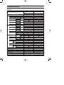
CONTENTS
Precautions
1
Product Specifications
2
Operation Instruction & Installation
3
Disassembly and Reassembly
10
Refrigerating Cycle Diagram
16
Feature & Operation
27
Set Up the Model Option
46
Troubleshooting
49
Exploded Views and Parts List
62
Block Diagram
67
PCB Diagram
68
Wiring Diagram
75
Schematic Diagram
77
DB98_20801A(1)_1
10/8/04 2:38 PM
Page 1
1. Precautions
11) Cut off the power.
● Make sure to cut off the power before repair. If not, you may
be damaged by an electric shock.
12) Do not install an outdoor unit on the apartment outside
wall(or equivalent) for safety.
● Installing an outdoor unit on the apartment outside wall(or
equivalent) is prohibited for the safety purpose. Service will
not be available for the outdoor unit where our servicemen
can not access and the cost of moving the outdoor unit to
the service area will be borne by the customer.
● If requested by the customer, you shall discourage him to
install an outdoor unit on the apartment outside wall(or
equivalent).
13) The air conditioner outdoor unit shall be installed 2m
above ground and kept away from pedestrians to prevent
direct exposure to hot wind. (according to the Building
Facility Standard Regulations)
14) Keep the drain hose outlet free.
● Otherwise, air flow will get slow, which may hinder cooling
capacity.
● Also, dew may be laden on the service valve.
15) Use of Certified Parts
● Use certified parts only. (An electric contact part, if broken
down, shall not be repaired but replaced with a new one.
Remodeling shall be prohibited. In no case, the customer
shall repair the product on his own because this is dangerous enough to bring about breakdown or fire.)
16) Ban on Middle Connection of Power Cord
● Do not cut the power cord in the middle to be connected to
other power cord nor use a middle socket between two
power cords. This is dangerous enough to bring about
breakdown or fire.
17) Check Insulation
● After assembly, be sure to check insulation resistance.
(Use an insulation ohmmeter to measure the insulation
resistance between the power cord and the earthing wire.
Do not supply power until it reads 30MΩ.)
18) Be sure to keep the symmetry of the product.
● Otherwise, you may hear vibration noise.
19) Caution for Children
● Do not keep children off the product while it is in repair.
Otherwise, they might be endangered.
10) Be sure to put the indoor or outdoor unit free of corrosive
gases such as sulfuric water, ammonium, and sulfuric
gas.
● Otherwise, copper tubes or soldered parts could be
corroded causing refrigerant leak.
11) Arrangement of surroundings
● After repair finishes, clean the air conditioner and its
surroundings and inform the customer of what it is like.
Samsung Electronics
1
DB98_20801A(1)_1
10/8/04 2:38 PM
Page 2
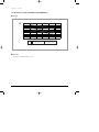
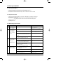
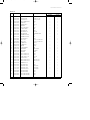
2. Product Specifications
2-1 Table
Model
Item
AS09HPA
Indoor unit
Type
Outdoor unit
Outdoor unit
Wall-mounted
kW
2.70
3.50
Heating
kW
2.90
3.80
Dehumidifying
|/h
1.0
1.4
Cooling
Air Volume
Heating
Performance
Cooling
Noise
Heating
Energy Efficiency Ratio
Cooling
Heating
Power
m3/min
dB
Operating Current
25
8.3 / 7.0 / 5.7
8.0 / 7.4 / 6.8
25
9.5 / 8.9 / 8.3
25
40 / 36 / 32
51 / 51
43 / 38 / 34
53 / 53
51 / 51
43 / 38 / 34
40 / 36 / 32
Cooling
Cooling
Starting Current
Length
840
1,090
850
1,180
3.9
5.0
Outer Dimension
Width x Height
x Depth
Weight(Net)
Refrigerant Pipe
98.0
28
m
2.1
2.1
5G
5G
A
250V-10A
250V-10A
mm
950 x 268 x 165
790 x 548 x 285
950 x 268 x 165
790 x 548 x 285
inch
37.4 x 10.6 x 6.5
31.1 x 21.6 x 11.2
37.4 x 10.6 x 6.5
31.1 x 21.6 x 11.2
kg
9.0
33.8
9.0
36.0
mm x L(m)
ø6.35 x 7.5
ø6.35 x 7.5
GAS
mm x L(m)
ø9.52 x 7.5
ø9.52 x 7.5
D x L(mm)
ø18 x 550
ø18 x 550
Rotary, G4A091JU
Rotary, G8C124JU
Type
Induction Motor(PSC)
Induction Motor(PSC)
Rated Output
Oil Type
Type
Motor
97.4
21
Type
Blower
5.4
98.2
Liquid
Drain Hose
Motor
3.7
97.6
A
Number of Core Wire
Capacity
Compressor
3.22
1-220 / 240-50
%
Heating
Power Cord
3.41
A
Heating
53 / 53
1-220 / 240-50
W
Heating
25
3.21
3.21
W/W
Cooling
Power Factor
Size
7.5 / 6.9 / 6.3
V-Hz
Power Consumption
Type
Rated Output
W
Heat Exchanger
Refrigerant Control Unit
2
Indoor unit
Wall-mounted
Cooling
Power
AS12HPA
930
1,267
DAPHNE FV68S(PVE)
DAPHNE FV68S(PVE)
Cross-flow
Propeller
Cross-flow
Propeller
Resin / steel
steel
Resin / steel
steel
15
50
15
50
2ROW 12STEP
1ROW 24STEP
2ROW 12STEP
2ROW 24STEP
CAPILLARY TUBE
CAPILLARY TUBE
Freezer Oil Capacity
cc
280
500
Refrigerant to Change(R410A)
g
730
950
Protection Device(OLP)
RBC12054-12500
Cooling Test Condition
INDOOR UNIT : DB27˚C WB19˚C
OUTDOOR UNIT : DB35˚C WB24˚C
Maximum Operation Condition
INDOOR UNIT : DB32˚C WB23˚C
OUTDOOR UNIT : DB43˚C WB26˚C
RBC12128-12500
Samsung Electronics
DB98_20801A(1)_1
10/8/04 2:38 PM
Page 3
3. Operation Instruction & Installation
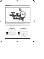
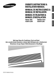
3-1 View of the Unit
3-1-1 Indoor Unit
Air Inlet
Temperature sensor
Power(On/Off) button
Air filter
(under the grille)
Airflow blades
(outlet)
Set temperature &
room temperature
Operation indicator
(Auto-Cool, Cool, Dry, Fan : Blue
Auto-Heat, Heat : Orange)
Auto cleaning indicator
(Blue)
Turbo function indicator
(Blue)
Energy saving indicator
(Blue)
Timer indicator
(Orange)
Anion indicator
(Blue)
Fan speed indicator
(Blue)
Remote control sensor
Samsung Electronics
3
DB98_20801A(1)_1
10/8/04 2:38 PM
Page 4
Operation Instruction & Installation
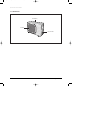
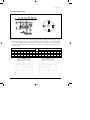
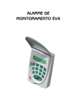
3-1-2 Outdoor Unit
Air Inlet(Rear)
Air Outlet
Connection Valve
4
Samsung Electronics
DB98_20801A(1)_1
10/8/04 2:38 PM
Page 5
3-2 Air Conditioner and Accessories
The following accessories are supplied with the air conditioner.
- The number of each accessory is indicated in parentheses.
3-2-1 Accessories in the Indoor Unit Case
Installation Plate (1)
Remote Control (1)
Batteries for
Remote Control (2)
User’s Manual (1)
TIONS
OWNER’S INSTRUC
INSTRUCCIONES
MANUAL DE
PER L’USO
ISTRUZIONIINSTRU
˝ES
MANUAL DE
TION
MANUEL D’UTILISAISUNG
GEBRAUCHSANWE
Air Conditioner
Splut-type Room stico sistema Split
dom
ad unit Separate
Aire acondicionado
d’aria per ambienti
Condizionatorede ar condicionado tipo Split
Aparelho
type s par
Climatiseur de
Geteilte raumklimaanlage
Installation Manual (1)
TIONS
OWNER’S INSTRUC
INSTRUCCIONES
MANUAL DE
PER L’USO
ISTRUZIONIINSTRU
˝ES
MANUAL DE
TION
MANUEL D’UTILISAISUNG
GEBRAUCHSANWE
Air Conditioner
Splut-type Room stico sistema Split
dom
ad unit Separate
Aire acondicionado
d’aria per ambienti
Condizionatorede ar condicionado tipo Split
Aparelho
type s par
Climatiseur de
Geteilte raumklimaanlage
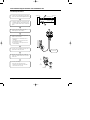
3-2-2 Accessories in the Outdoor Unit Case
5-wire
Assembly Cable (1)
Drain Plug (1)
Rubber Leg (4)
- The flare nuts are attached to the end of each pipe of an evaporator or a service port.
Use the nuts when connecting the pipes.
- The 5-wire assembly cable is optional. If it is not supplied, use the standard cable.
- The drain plug and rubber leg are only included when the air conditioner is supplied without the assembly pipe as seen in the
picture below.
The following connection accessories are optional.
If they are not supplied, you should prepare them before installing the air conditioner.
Assembly Pipe,
ø6.35mm by 7.5m (1)
Assembly Pipe,
ø9.52mm by 7.5m (1)
PE T3 Foam Tube
Insulation (1)
Vinyl Tape,
Width 50mm (1)
Drain Plug (1)
Rubber Leg (4)
Pipe Clamps A (3)
Pipe Clamps B (3)
Cement Nail (6)
M4 x 16 Tapping
Screws (10)
Drain Hose,
length 2m (1)
Putty 100g (1)
- If these accessories are supplied, you can find them in the accessory box.
Samsung Electronics
5
DB98_20801A(1)_1
10/8/04 2:38 PM
Page 6
3-3 Installation
3-3-1 Before Installation
Keep the air conditioner drain hose outlet and inlet free from its surroundings.
In case of breakdown, keep the symmetry and fix it to prevent vibration.
The pipe length shall meet the standard as far as possible.
3-3-2 Installation Procedure
■ Location
Install the product in an area to guarantee the best cooling effect, convenience of piping and electric work, and inexistence of
vibration or wind in the vicinity.
■ Wall Drilling
Drill the wall downward in a diameter of 60 to 65mm.
■ Fixing Indoor Unit & Outdoor Unit
Fix the air conditioner hard enough so that it can not fall to the ground. On the roadside, the outdoor unit shall be installed 2m
above ground and kept away from pedestrians to prevent direct exposure to hot wind.
■ Pipe Spooling & Connecting
You shall cut the pipe straightly with a pipe cutter and grind all the burrs of the cut surface.
Pipe expansion may continue until the pipe surface becomes uneven or torn apart.
Be sure to use a torque wrench to tighten pipes or flare nuts.
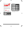
<Torque & Depth>
D
Outer Diameter(D)
Torque(kgf.cm)
Depth(A)
6.35mm(1/4")
140~170
1.3mm
9.52mm(3/8")
250~280
1.8mm
A
■ Leak Test
Put an inert gas like nitrogen in the outdoor unit pipe and put soap bubbles or other test liquids on the pipe surface for the leak test.
■ Drain Hose Connecting
Install the drain hose downward to drain water naturally. Be sure to pour water into the hose to check if it drains well.
■ Electric & Earth Work
Electric and earth work shall meet the "Electric Facility Technology Standard" and the "Internal Wire Regulation" of the Electric
Business Laws.
■ Inspection & Trial Run
Upon completion of the tests, you shall make a trial run while you explain the main functions of the air conditioner to finish the
installation.
6
Samsung Electronics
DB98_20801A(1)_1
10/8/04 2:38 PM
Page 7
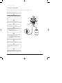
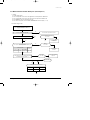
3-4 Installation Diagram of Indoor Unit and Outdoor Unit
3-4-1 Air-Purge Procedure
1) Connect each assembly pipe to the appropriate
valve on the outdoor unit and tighten the flare nut.
Indoor unit
Outdoor unit
A
Gas pipe side
C
B
Liquid pipe side
D
2) Connect the charging hose of low pressure side
of manifold gauge to the packed valve having a
service port (3/8" Packed valve) as shown at the
figure.
3) Open the valve of the low pressure side of
manifold gauge counter-clockwise.
4) Purge the air from the system using vacuum
pump for about 30 minutes.
- After that, please recheck that pressure is
stabilization.
- Close the valve of the low pressure side of
manifold gauge clockwise.
- Remove the hose of the low pressure side
of manifold gauge.
5) Set valve cork of both liquid side and gas side of
packed valve to the open position.
Vacuum Pump
6) Mount the valve stem nuts to the 2-Way and
3-Way valve. And mount the service port cap to
3-Way valve.
A
(gas)
7) Check for gas leakage.
- At this time, especially check for gas
leakage from the 3-Way valve’s stem nuts,
and from the service port cap.
B
(liquid)
Valve stem
Stem cap
Samsung Electronics
7
DB98_20801A(1)_1
10/8/04 2:38 PM
Page 8
Operation Instruction & Installation
3-4-2 Refrigerant Refill(R410A)
Refill an air conditioner with refrigerant when refrigerant has been leaked at installing or using.
1) Purge air(for new installation only).
2) Turn the 3-Way valve clockwise to close,
connect the pressure gauge (low pressure side)
to the service valve, and open the 3-Way valve
again.
Suspension hook
Compound
gauge
High
pressure
gauge
Hand
wheel
3) Connect the tank to refill with refrigerant.
4) Set the unit to cool operation mode.
Finger tight
fittings
For mounting
other and of
hose when
not in use
Connected to
high pressure
side
Charging line
5) Check the pressure indicated by the pressure
gauge(low pressure side).
* Standard pressure is should be 9.0~10.0kg/cm2
in a regular, high operation mode.
6) Open the refrigerant tank and fill with refrigerant
until the rated pressure is reached.
* It is recommended not to pour the refrigerant
in too quickly, but gradually while operating a
pressure valve.
7) Stop operation of the air conditioner.
8) Close the 3-Way valve, disconnect the
pressure gauge, and open the 3-Way valve
again.
9) Close the cap of each valve.
8
Samsung Electronics
DB98_20801A(1)_1
10/8/04 2:38 PM
Page 9
Operation Instruction & Installation
3-4-3 "Pump down" Procedure
Pump down will be carried out when an evaporator is replaced or when the unit is relocated in another area.
1) Remove the caps from the 2-Way valve and the
3-Way valve.
2) Turn the 3-Way valve clockwise to close and
connect a pressure gauge (low pressure side)
to the service valve, and open the 3-Way valve
again.
3-Way Valve
2-Way Valve
3) Set the unit to cool operation mode.
(Check if the compressor is operating.)
4) Turn the 2-Way valve clockwise to close.
5) When the pressure gauge indicates "0" turn the
3-Way valve clockwise to close.
6) Stop operation of the air conditioner.
7) Close the cap of each valve.
Relocation of the air conditioner
• Refer to this procedure when the unit is relocated.
• Carry out the pump down procedure (refer to the details of 'pump down').
• Remove the power cord.
• Disconnect the assembly cable from the indoor and outdoor units.
• Remove the flare nut connecting the indoor unit and the pipe.
• At this time, cover the pipe of the indoor unit and the other pipe using a cap or vinyl plug to avoid foreign
material entering.
• Disconnect the pipe connected to the outdoor unit.
At this time, cover the valve of the outdoor unit and the other pipe using a cap or vinyl plug to avoid foreign
material entering.
• Make sure you do not bend the connection pipes in the middle and store together with the cables.
• Move the indoor and outdoor units to a new location.
• Remove the mounting plate for the indoor unit and move it to a new location.
Samsung Electronics
9
DB98_20801A(1)_1
10/8/04 2:38 PM
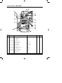
Page 10
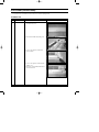
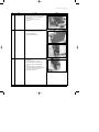
4. Disassembly and Reassembly
Stop operation of the air conditioner and remove the power cord before repairing the unit.
4-1 Indoor Unit
No
Parts
1
Panel Front
Procedure
Remark
1) Stop the air conditioner operation and
shut off the main power.
2) Detach the Front Grille after pushing out it.
3) Loosen 1 of the right screw and detach
the Ass'y display.
4) Loosen 1 of the right screw and detach the
Terminal Cover.
5) Detach the cover PCB-DVM and thermistor
from the Panel Front.
10
Samsung Electronics
DB98_20801A(1)_1
10/8/04 2:38 PM
Page 11
Disassembly and Reassembly
No
Parts
Procedure
Remark
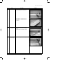
6) Loosen 5 fixing screws of Panel Front.
7) Unlock 2 hooks to fix Panel Front and
Tray Drain.
8) Unlock 2 hooks to fix Panel Front and
Back Body.
2
Tray Drain
1) Detach the connected wire of Stepping
Motor.
2) Pull Tray Drain out from the Back Body.
3
Heat Exchanger
1) Loosen 1 fixing earth screw of right side.
Samsung Electronics
11
DB98_20801A(1)_1
10/8/04 2:38 PM
Page 12
Disassembly and Reassembly
No
Parts
Procedure
Remark
2) Detach the Connection Pipe.
3) Detach the Holder Pipe at the rear side.
4) Loosen 3 fixing screws of left Holder Evap.
5) Loosen 1 fixing screw of right Holder
Motor.
6) Detach the Heat Exchanger from the
indoor unit.
12
Samsung Electronics
DB98_20801A(1)_1
10/8/04 2:38 PM
Page 13
Disassembly and Reassembly
No
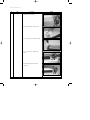
Parts
4
Electrical Parts
(Main PCB)
5
Fan Motor
&
Cross Fan
Samsung Electronics
Procedure
Remark
1) Loosen 4 fixing screws of right Holder
control.
2) Take all the connector of PCB upper side
out.(Including Power Cord)
3) Detach the outdoor unit connection wire
from the Terminal Block.
4) If pulling the main PCB up, it will be taken
out.
1) Loosen 2 fixing screws and detach the
Motor Holder.
2) Loosen 1 fixing screw of Fan Motor.
3) Detach the Fan Motor from the Fan.
4) Detach the Fan from the left Holder
Bearing.
13
DB98_20801A(1)_1
10/8/04 2:38 PM
Page 14
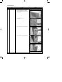
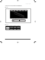
4-2 Outdoor Unit
No
Parts
1
Common Work
Procedure
Remark
1) Loosen each 3 fixing screws on both right
and left Cabinet-Side edge and a fixing
screw on the Cabinet-Front lower to detach
the Cabinet-Front.
2) Loosen 1 fixing screw of the
Ass'y-Control.
3) Loosen 6 fixing screws of the Cabinet-Side
RH.
4) Loosen 2 fixing screws of the Cabinet-Side
LF.
14
Samsung Electronics
DB98_20801A(1)_1
10/8/04 2:38 PM
Page 15
Disassembly and Reassembly
No
Parts
2
Fan & Motor
3
Heat Exchanger
4
Compressor
Samsung Electronics
Procedure
Remark
1) Detach the Nut Flange.(Turn counterclockwise because the screw is right-handed)
2) Detach the Fan.
3) Loosen 4 fixing screws to detach
the Motor.
1) Loosen 2 fixing screws on both sides.
2) Disassemble the pipe in both inlet and
outlet with welding torch.
3) Detach the Heat Exchanger.
1) Loosen the Terminal Cover nut to open the
Terminal Cover.
2) Disassemble the cloth sound felt.
3) Disassemble the pipe in both inlet and
outlet of the Compressor with welding
torch.
4) Disassemble the pipe in both inlet and
outlet of the Condenser with welding torch.
5) Loosen the 3 bolts at the bottom.
6) Detach the Compressor.
15
DB98_20801A(1)_1
10/8/04 2:38 PM
Page 16
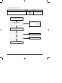
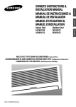
5. Refrigerating Cycle Diagram
5-1 Refrigerating Cycle Diagram
Outdoor Unit
Indoor Unit
✳Note
Capillary tube
T1
2-Way valve
Check valve
Liquid side
Heat
Exchanger
(Evaporator)
Cross fan
Heat
Exchanger
(Evaporator)
Propeller fan
Capillary tube
T2
Gas side
3-Way valve
4-Way valve
Cooling
Compressor
Heating
Gas Leak Check Polnt
16
Samsung Electronics
DB98_20801A(1)_1
10/8/04 2:38 PM
Page 17
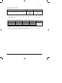
5-2 Refrigerant Cycle Characteristic
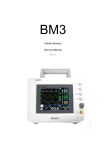
5-2-1 Capacity Distributions
Capacity Distributions according to indoor and outdoor temperature variation.
■ COOLING MODE
- Indoor Temp. Variation : 21.0˚C ~ 32.4˚C
- Outdoor Temp. Variation : 25.0˚C ~ 45.0˚C
■ AS09HPA
Cooling Capacity Distribution
Indoor Temp.( C)
Cooling Capacity(kW)
4.0
3.0
DB32.4 / WB24.0
DB30.6 / WB22.5
DB27.0 / WB19.0
2.0
DB24.0 / WB17.0
DB21.0 / WB15.0
1.0
25.0
35.0
45.0
Outdoor Temp.(DB C)
■ AS12HPA
Cooling Capacity Distribution
6.0
Indoor Temp.( C)
Cooling Capacity(kW)
5.0
4.0
DB32.4/WB24.0
DB30.6/WB22.5
DB27.0/WB19.0
DB24.0/WB17.0
DB21.0/WB15.0
3.0
2.0
1.0
0.0
25
35
45
Outdoor Temp.(DB C)
Samsung Electronics
17
DB98_20801A(1)_1
10/8/04 2:38 PM
Page 18
Refrigerating Cycle Diagram
■ HEATING MODE
- Indoor Temp. Variation : 15.0˚C ~ 25.0˚C
- Outdoor Temp. Variation : 1.0˚C ~ 20.0˚C
■ AS09HPA
Heating Capacity Distribution
Heating Capacity(kW)
4.00
Indoor Temp.( C)
DB15.0
DB20.0
DB25.0
3.00
2.00
1.00
1.0/0.0
7.0/6.0
20.0/15.0
Outdoor Temp.(DB/WB C)
■ AS12HPA
Heating Capacity
Heating Capacity Distribution
6.00
Indoor Temp.( C)
5.00
DB15.0
DB20.0
DB25.0
4.00
3.00
2.00
1.00
0.00
1.0/0.0
7.0/6.0
20.0/15.0
Outdoor Temp.(DB/WB C)
18
Samsung Electronics
DB98_20801A(1)_1
10/8/04 2:38 PM
Page 19
Refrigerating Cycle Diagram
5-2-2 Power Consumption Distributions
Power Consumption Distributions according to indoor and outdoor temperature variation.
■ COOLING MODE
- Indoor Temp. Variation : 21.0˚C ~ 32.4˚C
- Outdoor Temp. Variation : 25.0˚C ~ 45.0˚C
■ AS09HPA
Power consumption Distribution(Cooling mode)
Indoor Temp.( C)
1,100
DB32.4
DB30.6
DB27.0
DB24.0
DB21.5
Power consumption(W)
1,000
/
/
/
/
/
WB24.0
WB22.5
WB19.0
WB19.0
WB15.0
900
800
700
600
500
25
35
45
Outdoor Temp.(DB C)
■ AS12HPA
Power consumption(W)
Power consumption Distribution(Cooling mode)
1,400
Indoor Temp.( C)
1,300
DB32.4
DB30.6
DB27.0
DB24.0
DB21.5
/
/
/
/
/
WB24.0
WB22.5
WB19.0
WB19.0
WB15.0
1,200
1,100
1,000
900
800
25
35
45
Outdoor Temp.(DB C)
Samsung Electronics
19
DB98_20801A(1)_1
10/8/04 2:38 PM
Page 20
Refrigerating Cycle Diagram
■ HEATING MODE
- Indoor Temp. Variation : 15.0˚C ~ 25.0˚C
- Outdoor Temp. Variation : 1.0˚C ~ 20.0˚C
■ AS09HPA
Power consumption Distribution(Heating mode)
Indoor Temp.( C)
1,050
Power consumption(W)
DB25.0
950
DB20.0
DB15.0
850
750
650
1.0/0.0
7.0/6.0
20.0/15.0
Outdoor Temp.(DB/WB C)
■ AS12HPA
Power consumption Distribution(Heating mode)
Indoor Temp.( C)
DB25.0
Power consumption(W)
1,500
1,400
DB20.0
1,300
DB15.0
1,200
1,100
1,000
900
25
35
45
Outdoor Temp.(DB/WB C)
20
Samsung Electronics
DB98_20801A(1)_1
10/8/04 2:38 PM
Page 21
Refrigerating Cycle Diagram
5-2-3 Capacity and Power Consumption Distributions
Capacity and power Consumption distributions according to the length of connecting Pipe between indoor unit and outdoor unit.
■ COOLING MODE
■ AS09HPA
Power consumption(Cooling)
Cooling Capacity
1,100
Power consumption(W)
Coooling Capacity(kW)
4
3
2
1
7.5
1,000
900
800
700
600
500
15.0
7.5
Length of Connecting Pipe(m)
15.0
Length of Connecting Pipe(m)
■ AS12HPA
Power consumption(Cooling)
Cooling Capacity
1,300
Power consumption(W)
Cooling Capacity(kW)
3.70
3.50
3.30
3.10
1,100
1,000
900
2.90
7.5
15.0
Length of Connecting Pipe(m)
Samsung Electronics
1,200
7.5
15.0
Length of Connecting Pipe(m)
21
DB98_20801A(1)_1
10/8/04 2:38 PM
Page 22
Refrigerating Cycle Diagram
■ HEATING MODE
■ AS09HPA
Power consumption(Heating)
Heating Capacity
1,050
Power consumption(W)
Heating Capacity(kW)
4.00
3.00
2.00
1.00
7.5
950
850
750
650
7.5
15.0
Length of Connecting Pipe(m)
15.0
Length of Connecting Pipe(m)
■ AS12HPA
Power consumption(Heating)
Heating Capacity
1,350
Power consumption(W)
Heating Capacity(kW)
4.30
4.10
3.90
3.70
3.50
7.5
15.0
Length of Connecting Pipe(m)
22
1,250
1,150
1,050
950
7.5
15.0
Length of Connecting Pipe(m)
Samsung Electronics
DB98_20801A(1)_1
10/8/04 2:38 PM
Page 23
Refrigerating Cycle Diagram
5-2-4 Low Pressure Distributions
■ COOLING MODE
- Indoor Temp. Variation : 21.0˚C ~ 32.4˚C
- Outdoor Temp. Variation : 25.0˚C ~ 45.0˚C
■ AS09HPA
Low Pressure Distribution(Cooling mode)
Indoor Temp.( C)
Low pressure(kg/cm G)
12.0
DB32.4 / WB24.0
DB30.6 / WB22.5
10.0
DB27.0 / WB19.0
DB24.0 / WB17.0
DB21.0 / WB15.0
8.0
6.0
25
35
45
Outdoor Temp.(DB C)
■ AS12HPA
Low Pressure Distribution(Cooling mode)
Indoor Temp.( C)
Low pressure(kg/cm G)
15.0
13.0
11.0
DB32.4
DB30.6
DB27.0
DB24.0
DB21.5
9.0
/
/
/
/
/
WB24.0
WB22.5
WB19.0
WB19.0
WB15.0
7.0
5.0
25
35
45
Outdoor Temp.(DB C)
Samsung Electronics
23
DB98_20801A(1)_1
10/8/04 2:38 PM
Page 24
Refrigerating Cycle Diagram
5-2-5 Air Volume according to the RPM variation(High/Mid/Low)
■ Indoor Unit
10
9.5
9
8.5
8
7.5
7
6.5
6
5.5
5
High
Mid
Low
12,000BTU-Cooling-Vol.
12,000BTU-Heating-Vol.
19,000BTU-Cooling-Vol.
19,000BTU-Heating-Vol.
RPM
■ Outdoor Unit
The air volume is 25m3/min regardless of model.
24
Samsung Electronics
DB98_20801A(1)_1
10/8/04 2:38 PM
Page 25
Refrigerating Cycle Diagram
5-2-6 Noise Level according to the RPM variation(High/Mid/Low)
■ Indoor Unit
dB 41
39
37
35
33
31
29
27
High
Mid
Low
12,000BTU-Cooling-Noise
12,000BTU-Heating-Noise
19,000BTU-Cooling-Noise
19,000BTU-Heating-Noise
RPM
■ Outdoor Unit
Section
AS09HPA
AS12HPA
Samsung Electronics
Operation
Noise(dB)
Cooling
51
Heating
51
Cooling
53
Heating
53
Remark
25
DB98_20801A(1)_1
10/8/04 2:38 PM
Page 26
5-3 Cautions Of using for R410A
■ HFCs
1. When installing or removing or servicing an air conditioner, do not allow air or moisture to remain in the refrigeration cycle.
2. When evacuating an air conditioner, always use the vacuum pump and sufficiently evacuate an air conditioner.
3. Certainly use the specified lubricant(Polyol ester oil), valve and dryer.
■ Lubricants
1. Synthetic Oils : POE, PVE, PAG, AB
2. POE is made from Acid and Alcohol
1. RCOOH(Carboxylic Acid) + R'OH(Alcohol) ↔ RCOOR'(Ester) + H2O(Water)
3. Hydrolysis causes Metallic Soap
1. RCOOR' + H2O → RCOOH + R'OH
1. FeO + 2RCOOH → Fe(COOR)2(Carboxylic Acid Iron(slurgy))
26
Samsung Electronics
DB98_20801A(1)_1
10/8/04 2:38 PM
Page 27
6. Feature & Operation
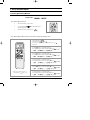
6-1 The Feature of Key in remote control
No
1
NAMED OF KEY
FUNCTION OF KEY
(On/Off)
On/Off button.
Press the
button to stop or run the air conditioner.
(UP)
Temperature adjustment button(UP).
To increase the temperature by the pressing the temperature button.
(DOWN)
Temperature adjustment button(DOWN).
To decrease the temperature by the pressing the temperature button.
2
3
Mode selection button.
Each time you press this button
Mode is changed in the following order
: Auto Mode
: Fan Mode
: Cool Mode
: Heat Mode
: Dry Mode
Fan speed adjustment button.
Each time you press this button, FAN SPEED is changed in the following order.
4
Low
Medium
High
Automatic(rotated :
)
5
Swing button.
It adjusts the airflow to upward and downward.
6
Turbo button.
The air conditioner cools or heats the room as quickly as possible.
After 30 minutes, the air conditioner is reset automatically to the previous mode.
7
Energy saving button.
If you wish to save energy when using your air conditioner, select the Energy saving
mode with the
button.
8
Auto Clean button.
If you want to clean the indoor airconditioner after operation, press the
Samsung Electronics
button.
27
DB98_20801A(1)_1
10/8/04 2:38 PM
Page 28
The Feature of Key in remote control(cont.)
No
9
10
NAMED OF KEY
FUNCTION OF KEY
Sound On/Off button.
Press the
button not to make a buzzer sound.
On Timer button.
The On Timer enables you to switch on the air conditioner automatically after
a given period of time that is from 30 minutes to 24 hours.
To set the operating time, press the
time display.
11
Off Timer button.
The Off Timer enables you to switch off the air conditioner automatically after
a given period of time that is from 30 minutes to 24 hours.
To set the operating time, press the
time display.
12
button one or more times until the required
button one or more times until the required
Timer Set/Cancel button.
After setting On Timer or Off Timer, press the
And press the
button to set it completely.
button again to cancel On Timer or Off Timer set.
13
Anion button.
Press the
button to generate ion from the air conditioner.
14
Sleep button.
The sleep timer can be used when you are cooling or heating your room to switch the
air conditioner off automatically after a period of 6 hours.
15
Digital On/Off button.
If you want to turn off the display during operation press the
28
button.
Samsung Electronics
DB98_20801A(1)_1
10/8/04 2:38 PM
Page 29
6-2 Details for Operation Property
1.
AUTO MODE : In this mode, operation mode(COOL,
HEAT) is selected automatically by the difference
between the setting and room temperature.
4.
DRY MODE : Has 4 states, each determined by room
temperature.
The unit operates in DRY mode.
*Compressor ON/OFF time is controlled compulsorily
(can not set up the fan speed, always breeze).
*Protective function : Low temperature release.
(Prevention against freeze)
5.
TURBO MODE : This mode is available in AUTO, COOL,
HEAT, DRY, FAN MODE.
When this button is pressed at first, the air conditioner is
operated "powerful" state for 30 minutes regardless of the
setting temperature, room temperature.
When this button is pressed again, or when the operating
time is 30 minutes, turbo operation mode is canceled and
returned to the previous mode.
*But, if you press the TURBO button in DRY or FAN
mode that is changed with AUTO mode automatically.
6.
SLEEP MODE : Sleep mode is available only in COOL or
HEAT mode.
The operation will stop after 6 hours.
*In COOL mode : The setting temperature is automatically
raised by 1°C each 1hour When the temperature has
been raised by total of 2°C, that temperature is
maintained.
*In HEAT mode : The setting temperature is automatically
dropped by 1°C each 1 hour.
When the temperature has been dropped by total of
2°C, that temperature is maintained.
7.
FAN SPEED : Manual (3 step), Auto (4 step)
Fan speed automatically varies depending on both the
difference between setting and the room temperature.
8.
COMPULSORY OPERATION :
For operating the air conditioner without the remote
control.
*The operating is the same function that AUTO MODE in
the remote control.
√ In case of Heat pump model.
√ Cooling or heating operation is selected based on
difference of Ts and Tr. Cooling and heating operation
is automatically interchanged during an operation.
√ In case of Cooling only model.
Operation Type
Cool Operation
Room Temp.
Tr ≥ Ts+1.0°C
Compressor ON
Tr ≤ Ts
Compressor OFF
Ts : Setting temperature. Tr : Room temperature.
2.
COOL MODE : The unit operates according to the
difference between the setting and room temperature.
(16°C~30°C)
3.
HEAT MODE(In case of Heat pump model) :
The unit operates according to the difference between the
setting and room temperature.(16°C~30°C)
*Prevention against cold wind : In order to prevent the
cool air from flowing out at the heat mode, the indoor fan
does not operate or operates very slowly in the following
cases At this time, the indoor heat exchanger will be
preheated.
- For 3~5 minutes after the initial operation
- For deicing operation
- The operation of an indoor fan in accordance with the
temperature of an indoor heat exchanger
The temperature of
indoor heat exchanger
Indoor fan speed
below 28˚C
off
28˚C~below 34˚C
LL Speed
34˚C~below 40˚C
L Speed
above 40˚C
Setting Speed
*High temperature release function : It is a function to
detect an outdoor overload by the sensor of an indoor
heat exchanger and to turn the outdoor fan or the
compressor ON/OFF for safety.
*Deice : Deicing operation is controlled by indoor unit's
heat exchanger temperature and accumulating time of
compressor's operation.
Deice ends by sensing of the processing time by deice
condition.
Samsung Electronics
29
DB98_20801A(1)_1
10/8/04 2:38 PM
Page 30
Feature & Operation
9.
SWING : BLADE-H is rotated vertically by the stepping
motor.
*Swing Set : Press the
button under the remote
control is displayed on LCD the
and the blades
move up and down. If the one more time press the
button, blades location is stop.
10. SETTING THE ON/OFF TIMER. :
*ON TIMER : The On Timer enables you to switch on the
air conditioner automatically after a given period of time.
You can set the period of time from 30 minutes to 24
hours.
*OFF TIMER : The Off Timer enables you to switch off
the air conditioner automatically after a given period of
time. You can set the period of time from 30 minutes to
24 hours.
11. GENERATING ANION :
The air conditioner can generate anion with an ionizer in
the indoor unit.
12. Auto Clean
When the air conditioner
is turned
On
Off
30
Mode
Operating time
Auto, Cool, Dry
30 minutes
Heat, Fan
15 minutes
Auto, Cool, Dry
Heat, Fan
30 minutes
13. SELF DIAGNOSIS
Error Mode
DISPLAY 7-SEGMENT
Remark
Operation Off Operation On
Indoor unit room temperature sensor
error (open or short)
OFF
E1
Indoor unit heat exchanger
temperature sensor error(open or short)
OFF
E2
Indoor FAN MOTOR error :
Keep the RPM value 450 below for
15 seconds
OFF
E3
EEPROM error
OFF
E6
All lamp
blinking
All lamp
blinking
Error in option
In case of No option set-up
In case of option data error
14. BUZZER SOUND : Whenever the On/Off button is
pressed or whenever change occurs to the condition
which is set up or select, the compulsory operation mode,
buzzer is sounded "beep".
Samsung Electronics
DB98_20801A(1)_1
10/8/04 2:38 PM
Page 31
Feature & Operation
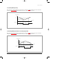
6-2-1 Cooling Mode Operating
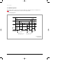
When selecting the Cooling Mode Operation, the unit will operate according to the setting temperature by the remote control and the
operation is as well as the following. Room temperature can be set in 1°C steps in the range of 16 to 30°C.
Room Temp.(°C)
Ts+1
Ts
Time
ON
ON
Compressor
OFF
♦ Ts means Remote Controller setting Temperature
6-2-2 Heating Mode Operation(In case of Heat pump model)
When selecting the Heating Mode Operation, the unit will operate according to the setting temperature by the remote control and the
operation is as well as the following. Room temperature can be set in 1°C steps in the range of 16 to 30°C.
Room Temp.(°C)
Ts+5
Ts+3
Time
ON
Compressor
ON
ON
OFF
Samsung Electronics
31
DB98_20801A(1)_1
10/8/04 2:38 PM
Page 32
Feature & Operation
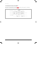
6-2-3 Automatic Operation
When Automatic operation is set by the remote control, the air conditioner senses the difference between room temperature and
setting temperature then automatically selects the operation mode and setting temperature.
1. In case of Heat pump model.
Ts+4
A area
Ts+3
Ts+2
B area
Ts+1
C area
Ts
Ts-1
C' area
Ts-2
B' area
Ts-3
Ts-4
COMPor
A' area
ON
Over 1hour
OFF
Cooling / Heating
Mode
Cooling Mode
Less
than
1hour
Heating Mode
Cooling Mode
• A area : Tr ≥ Ts+3˚C
• C' area : Ts > Tr ≥ Ts-1˚C
• B area : Ts+3˚C > Tr ≥ Ts+2˚C
• B' area : Ts-1˚C > Tr ≥ Ts-3˚C
• C area : Ts+2˚C > Tr ≥ Ts
• A' area : Ts-3˚C > Tr
◆ Tr : Room temperature.
◆ Ts : Setting temperature.
32
Samsung Electronics
DB98_20801A(1)_1
10/8/04 2:38 PM
Page 33
Feature & Operation
● Initial operating (Cooling/Heating) mode setup
● 1. When operation is on with the automatic mode at power reset, or when selecting the automatic mode at the other mode
●
●
●
●
before, not the automatic mode.
1. 1) "Room Temperature ≥ Setting Temperature"
1. 1) ➞ Automatic cooling operation with the setting temperature as a target
1. 2) "Room Temperature < Setting Temperature"
1. 1) ➞ Automatic heating operation with the setting temperature as a target
● 2. Turned off with automatic mode selected and turned on again
● 1. 1) If cooling operation was running in the previous automatic mode.
Room temperature (Tr) area
when the power is turned on.
While the power is turned down
Mode configuration for
the power on.
A, B, C area
Independent to time
Set cooling mode
C' area
B' area
A' area
Within 1 hour from the power off.
Set cooling mode
1 hour after the power off
Set heating mode
Within 1 hour from the COMPor off
Set cooling mode
1 hour after the COMPor off
Set heating mode
After 3 minutes delay of the COMPor
Set heating mode
● 1. 2) If heating operation was running in the previous automatic mode.
Room temperature (Tr) area
when the power is turned on.
While the power is turned down
Mode configuration for
the power on.
A', B', C' area
Independent to time
Set heating mode
Within 1 hour from the power off.
Set heating mode
1 hour after the power off
Set cooling mode
Within 1 hour from the COMPor off
Set heating mode
1 hour after the COMPor off
Set cooling mode
After 3 minutes delay of the COMPor
Set cooling mode
C area
B area
A area
2. In case of Cooling only model.
Operating Type
Cool Operation
Room Temp.
Tr ≥ Ts+1.0˚C
Compressor ON
Tr ≤ Ts
Compressor OFF
◆ In case the Room Temp. ≥ Ts+1.0˚C the unit is operated Compressor.
◆ In case the Room Temp. ≤ Ts the unit is not operated Compressor.
◆ Tr : Room temperature.
◆ Ts : Setting temperature.
Samsung Electronics
33
DB98_20801A(1)_1
10/8/04 2:39 PM
Page 34
Feature & Operation
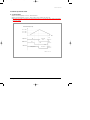
6-2-4 Dry Operation Control
● Operation pattern
✳ Ts=Remote Control Set Temp.
Room Temp.(˚C)
(I-Mode)
Ts+4
(II-Mode)
Ts+3
Ts+2
(III-Mode)
Ts+2
Ts
Ts-1
(IV-Mode)
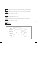
● Operation Specification
◆
1. ON/OFF Time by Dry Modes
1
1
1
1
1
◆
Operation Cycle(Min.)
COMPOR &
Outdoor Fan
I-Mode
II-Mode
III-Mode
ON Time
6 Min.
5 Min.
4 Min.
OFF Time
4 Min.
5 Min.
6 Min.
IV-Mode
COMPOR=OFF
1) Select a dry operation mode (I, II, III or IV) based on the room temperature.
"Room Temp. > Ts+4" = Dry I-Mode
"Room Temp. < Ts+1" = Dry III-Mode
Other than Dry I-Mode and III-Mode = Dry II-Mode
In Dry III-Mode, "Room Temp. ≤ Set Temp.-1" = Dry IV-Mode
2. COMP OR and Indoor Fan Operation Cycle
COMPOR
Operation
ON
Indoor Fan
Operation
OFF
ON
OFF
ON
OFF
LL
Initial setup
6 min.
Operation
3 min
1st CYCLE
3 min
2nd CYCLE
3 min
Judge the next dry mode after 3 min. from COMPOR ON.
34
Samsung Electronics
DB98_20801A(1)_1
10/8/04 2:39 PM
Page 35
Feature & Operation
6-2-5 Sleeping Operation
● AT COOLING MODE
When you set the sleep mode, the following movement will start to avoid over cooling.
◆ The indoor fan speed is fixed by setting the remote control.
◆ The setting temperature will rise by 1°C at the starting of operation and by 1°C 1 hour later.
◆ The operation will stop after 6 hours.
6h
1h
1h
Ts+2
1°C up
Ts+1
1°C up
Ts
Stop
Start
● AT HEATING MODE
When you set the sleep mode, the following movement will start to avoid overheating.
◆ The indoor fan speed is fixed by setting the remote control.
◆ The setting temperature will be dropped by 1°C at the starting of operation and by 1°C 1 hour later.
◆ The operation will stop after 6 hours.
Stop
Start
Ts+5
1°C down
Ts+4
1°C down
Ts+3
Ts+3
Ts+2
Ts+1
1h
1h
6hr
Samsung Electronics
35
DB98_20801A(1)_1
10/8/04 2:39 PM
Page 36
Feature & Operation
6-2-6 Turbo Operation (Cooling or Heating Mode)
If turbo operation is selected during heating or cooling mode, compressor is operated for 30 minutes regardless of room temperature.
After 30minutes of turbo operation the unit will operate in normal state.
High(HEAT)
Turbo(COOL)
<Indoor FAN Speed>
Setting Speed
Setting Speed
30 min
<COMP_or Control>
<Operation MODE>
COMP or ON
TURBO Operation
TURBO Operation
Start
36
TURBO Operation
End
Samsung Electronics
DB98_20801A(1)_1
10/8/04 2:39 PM
Page 37
Feature & Operation
6-2-7 Energy saving operation control
● In case of Cooling Only model
l
The Energy saving mode is applicable to only in both the COOL mode and AUTO mode.
● In case of Heat Pump model
l
The Energy saving mode is applicable to only in the COOL mode.
● Energy saving operation specification
- If you select the Energy saving mode during automatic operation, the setting temperature(Ts) will be fixed to "the standard value
+2°C"(26°C).
- If you select the Energy saving mode during cooling operation, you may set the room temperature from "26°C to 30°C",
but if you hope to control the room temperature below 26°C in the Energy saving mode, the room temperature will be
compelled to be 26°C.
- If you select the Energy saving mode, the up/down louver will enter the "Swing" status.
● ◆ Operation pattern A : In the Energy saving mode when Room Temperature(Tr) equals to the Setting Temperature(Ts) or over.
Temperature
Tg +ß
Energy saving
mode
Ts+1
Ts
General operation mode
Tg
→
Time
COMP_or
ON
Energy saving mode starting
OFF
● ◆ Operation pattern B : In the Energy saving mode when Room Temperature(Tr) is below the Setting Temperature(Ts).
Temperature
Energy saving Ts+1
Energy saving Ts
Tg +ß
Energy saving
mode
Tg +ß
Tg←Tg+α
Tr
Ts
Tg←Tg+α
Tg
COMP_or
Samsung Electronics
ON
Energy saving
mode starting
Energy saving
pattern mode B
→
→
General operation
mode
Time
Change the Energy
saving pattern A.
OFF
37
DB98_20801A(1)_1
10/8/04 2:39 PM
Page 38
Feature & Operation
6-2-8 Indoor fan control in the Heating Mode
Indoor fan is controlled depending on the temperature of indoor heat exchanger in the heating mode.
● INDOOR FAN CONTROL
◆ When compressor begins operating
The temperature of indoor heat exchanger
Indoor fan speed
below 28°C
off
28°C ~ below 34°C
LL speed
34°C ~ below 40°C
L speed
above 40°C
setting speed
◆ When compressor stops operating
The temperature of indoor heat exchanger
Indoor fan speed
above 20°C
UL speed
below 20°C
off
after 10 minutes when compressor stops operating
off
When compressor is off
When compressor is on
40°C
34°C
28°C
20°C
Setting speed
L Speed
LL Speed
OFF
UL
ON
Compressor
38
OFF
OFF
Samsung Electronics
DB98_20801A(1)_1
10/8/04 2:39 PM
Page 39
Feature & Operation
6-2-9 Overload protection control
● AT HEATING MODE
◆ If indoor heat exchanger temp. is over 53°C, outdoor fan turns off.
◆ If indoor heat exchanger temp. is over 60°C, outdoor compressor stops and Indoor fan speed is low.
◆ After compressor and fan are off if indoor heat exchanger temp. is below 50°C, indoor fan and outdoor compressor and outdoor
fan operate normally.
Indoor Heat Exchanger Temp.
60˚C + offset
53˚C + offset
50˚C + offset
Time
Compressor
3min Delay
ON
ON
OFF
Outdoor Fan
ON
ON
OFF
2Sec
Indoor Fan
Setting Speed
Low Speed
*offset = 0, 1, 2, 3˚C
Samsung Electronics
39
DB98_20801A(1)_1
10/8/04 2:39 PM
Page 40
Feature & Operation
6-2-10 Low Temp Release
● AT COOLING MODE
◆ If the temperature of indoor heat exchanger is below -1°C for over 6minutes, the outdoor fan turns off.
◆ If the temperature of indoor heat exchanger increase over 5°C during the first protection function, the first freezing protection
function is released and the outdoor fan turns on.
◆ If the temperature of indoor heat exchanger increase over 0°C during 6 minutes counting, 6 minutes counter is cleared.
◆ If the temperature of indoor heat exchanger maintains for a minute at -4°C during the 6 minutes counting, switch off the
compressor.
◆ If the compressor is off by Low Temp. Release, 5 minutes release is impossible.
◆ Operation pattern
Indoor Heat exchanger Temp.(˚C)
5[˚C]
0[˚C]
-1[˚C]
6min
6min
COUNT COUNT
ON
OFF
6min
COUNT
ON
6min
Low temp.
release
OFF
Low temp.
release
ON
3sec
COMP_or
ON
OFF
ON
2sec
Outdoor FAN
ON
OFF
ON
Indoor FAN
Setting Fan speed
"LL"
Setting Fan speed
*LL = Low FAN speed – 35rpm
40
Samsung Electronics
DB98_20801A(1)_1
10/8/04 2:39 PM
Page 41
Feature & Operation
6-2-11 Defrost control
Defrost operation is controlled by sensing the temperature of indoor heat exchanger.
◆ How to sense defrost conditions
A condition
The temperature of indoor heat exchanger is checked in intervals of 1 minute. In case the temperature of indoor heat exchanger drops more
than 0.5°C for 6 minutes, it is considered as one cycle. If it happens 3 times continuously, It is said that "A condition" is satisfied.
B condition
If the temperature of indoor heat exchanger is below about 40±3°C when the compressor is on, it is considered as defrost "B condition"
C condition
When the accumulating time of compressor ON is over 20 minutes.
D condition
When the accumulating time of compressor ON is over 3Hr.
E condition
When operating time of compressor without stopping is over 6 minutes.
F condition
If the compressor is off(thermo off) when the temperature of indoor heat exchanger is below about 46°C, it is considered as one cycle.
If it happens 2 times continuously, It is said that "F condition" is satisfied.
G condition
When the accumulating time of compressor ON is over 90 minutes.
◆ Defrost operation conditions
A✕B✕C condition or
B✕D✕E condition
F✕G condition
Defrost time : 5~8 minutes
◆ Operation pattern
Defrost Time
Defrost
Compressor
1min
ON
ON
OFF
OFF
Outdoor Fan
ON
ON
more than 58sec
Thermo ON
OFF
2sec
4Way Valve
ON
ON
55sec
55sec
OFF
Indoor Fan
Setting Speed
ON
1min
OFF
Samsung Electronics
Low Speed
41
DB98_20801A(1)_1
10/8/04 2:39 PM
Page 42
Feature & Operation
6-2-12 Auto Clean Mode
1.
When the air conditioner is turned
Mode
On
Off
Operating time
Auto, Cool, Dry
30 minutes
Heat, Fan
15 minutes
Auto, Cool, Dry
Heat, Fan
30 minutes
2. Indoor Fan Airflow Control
2. After Heat Mode : Ultra Low(510 rpm)
2. Except Heat Mode : Low
COMP_or
ON
OFF
ON
OFF
Outdoor Fan
Indoor Fan
Setting Fan Speed
Low Fan speed
(UL airflow on Heat mode)
OFF
30 minutes
(15 minutes on heat mode or fan mode)
Start “Auto clean mode”
42
Power Off
Samsung Electronics
DB98_20801A(1)_1
10/8/04 2:39 PM
Page 43
Feature & Operation
6-2-13 Test Operation Method
1. Press the ON/OFF button of the indoor unit for at least 5 seconds.
2. Check the operation of the set mainly for the following points.
◆ 1) OPERATION MODE : COOLING
◆ 2) FAN SPEED : HIGH
◆ 3) AIR FLOW DIRECTION : SWING
◆ 4) DISPLAY : OPERATING LED ON
◆ 5) OUT DOOR LOAD : OUT FAN ON, COMP ON
3. Check if the set is in normal operation.
4. Press the ON/OFF button again to switch the power off.
Samsung Electronics
43
DB98_20801A(1)_1
10/8/04 2:39 PM
Page 44
6-3 Circuit Description
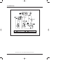
6-3-1 Indoor Fan Control
ZERO CROSSING PARTS
■
Use SSR(Solid State Relay) of Micom to change the ON Time until the 220V sine wave equals the fan motor rpm to control. In the
meantime, the Zero Crossing part will recognize AC220V as 0V to determine the Switching Timing.
As the Fan Control Port of Micom detects the "High" signal and the signal turns into "Low" past TR-Array(UL2003), the LED of SSR
obtains 12V, the same input wave with "2" and the Gate of Photo Triac obtains the operating voltage at the same time to determine
the time to turn on SSR. Now the indoor fan motor can operate at the desired rpm.
High RPM
44
Low RPM
Voltage
Voltage
Current
Current
Samsung Electronics
DB98_20801A(1)_1
10/8/04 2:39 PM
Page 45
Feature & Operation
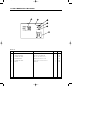
6-3-2 Stepping Motor Control
S1
M
S4
S2
S3
■
As shown in the above figure, let the electric currents in sequence flow through the 4 windings to revolve the stepping motor. Of 3
methods of 4 couple stepping switch sequence, 1 Phase Exciter Method, 2 Phase Exciter Method, and 1-2 Phase Exciter Method,
the last method was adopted for this circuit. Based on this method, the signals come in the order of S1, S2, S3, and S4 to create
magnetic force and one frequency forms a cycle. When S1, S2, S3, and S4 receive the following signals respectively, the stepping
motor begins operation.
Power OFF (Closing) CCW ("1"=HIGH)
Power ON (Opening) CW ("0"=LOW)
Switch
1
2
3
4
5
6
7
8
1
2
3
4
5
6
7
8
1
1
0
0
0
0
0
0
S1
0
0
0
0
0
1
1
1
0
1
1
1
0
0
0
0
S2
0
0
0
1
1
1
0
0
0
0
0
1
1
1
0
0
S3
0
1
1
1
0
0
0
0
0
0
0
0
0
1
1
1
S4
1
1
0
0
0
0
0
0
Power OFF
Power ON
S1
S1
S2
S2
S3
S3
S4
S4
Samsung Electronics
45
DB98_20801A(1)_1
10/8/04 2:39 PM
Page 46
7. Set Up the Model Option
7-1 Setting Option Setup Method
ex) Option No. :
Step 1 : Enter the Option Setup mode.
1st
Take out the batteries of remote control.
2nd
Press the temperature
insert the battery again.
3rd
Make sure the remocon display shown as
button simultaneously and
.
Step 2 : Enter the Option Setup mode and select your option according to the following procedure.
1
The default value is
Otherwise, push the
.
button to
.
Every time you push the button, the display panel reads
or
repeatedly.
2
3
button to set the display panel to
.
Every time you push the button, the display panel reads
...
repeatedly.
2
3
1
Push the
button to set the display panel to
.
Every time you push the button, the display panel reads
...
repeatedly.
4
5
Push the
6
4
Push the
button to set the display panel to
.
Every time you push the button, the display panel reads
...
repeatedly.
5
Push the
button to set the display panel to
.
Every time you push the button, the display panel reads
...
repeatedly.
6
✳ Setting is not required if you must
a value which has a
default.
46
Push the
button to set the display panel to
.
Every time you push the button, the display panel reads
...
repeatedly.
Samsung Electronics
DB98_20801A(1)_1
10/8/04 2:39 PM
Page 47
Set Up the Model Option
7
Press
button, then the default value is
.
8
Push the
button to set the display panel to
.
Every time you push the button, the display panel reads
...
repeatedly.
9
8
9
Push the
button to set the display panel to
.
Every time you push the button, the display panel reads
...
repeatedly.
7
10
10
11
Push the
12
button to set the display panel to
.
Every time you push the button, the display panel reads
...
repeatedly.
11
Push the
button to set the display panel to
.
Every time you push the button, the display panel reads
...
repeatedly.
12
Push the
✳ Setting is not required if you must
a value which has a
default.
button to set the display panel to
.
Every time you push the button, the display panel reads
...
repeatedly.
Step 3 : Upon completion of the selection, check you made right selections.
Press the Mode Selection key,
The display part shows
Press the Mode Selection key,
The display part shows
to set the display part to
and check the display part.
.
to set the display part to
and check the display part.
.
Step 4 : Pressing the ON/OFF button (
)
When pressing the operation ON/OFF key with the direction of remote control for unit, the sound ''Ding'' or ''Diriring'' is
heard and the OPERATION ICON(
) lamp of the display is flickering at the same time, then the input of option is completed. (If the diriring sound isn't heard, try again pressing the ON/OFF button.)
Step 5 : Unit operation test-run
First, Remove the battery from the remote control.
Second, Re-insert the battery into the remote control.
Third, Press ON/OFF key with the direction of remote control for set.
• Error Mode
1st If all lamps of indoor unit are flickering, plug out, plug in battery again and press the ON/OFF key to retry.
2nd If the unit is not working properly or all lamps are continuously flickering after setting the option code, see if the correct option code is
set up for its model.
Samsung Electronics
47
DB98_20801A(1)_1
10/8/04 2:39 PM
Page 48
Set Up the Model Option
■ OPTION ITEMS
REMOCON
SEG1
SEG2
SEG3
SEG4
SEG5
SEG6
SEG7
SEG8
SEG9 SEG10 SEG11 SEG12
AS09HPA
0
2
8
0
2
5
1
2
1
2
2
8
AS12HPA
0
2
7
3
2
7
1
7
1
2
6
c
MODEL
48
Samsung Electronics
DB98_20801A(1)_1
10/8/04 2:39 PM
Page 49
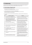
8. Troubleshooting
8-1 Items to be checked first
1.
The input voltage should be rating voltage ±10% range.
The airconditioner may not operate properly if the voltage is out of this range.
2.
Is the link cable linking the indoor unit and the outdoor unit linked properly?
The indoor unit and the outdoor unit shall be linked by 5 cables.
Check the terminals if the indoor unit and outdoor unit are properly linked by the same number of cables.
Otherwise the airconditioner may not operate properly.
3.
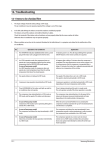
When a problem occurs due to the contents illustrated in the table below it is a symptom not related to the malfunction of the
airconditioner.
No
Operation of air conditioner
Explanation
1
The OPERATION indication LED(BLUE) blinks when a
power plug of the indoor unit is plugged in for the first time.
It indicates power is on. The LED stops blinking if the operation ON/OFF button on the remote control unit is pushed.
2
In a COOL operation mode, the compressor does not
operate at a room temperature higher than the setting
temperature that the INDOOR FAN should operate.
[In case of heat pump model]
In a HEAT operation mode, the compressor does not
operate at a room temperature lower than the setting
temperature that indoor fan should operate.
In happens after a delay of 3 minutes when the compressor
is reoperated. The same phenomenon occurs when a power
is on.
As a phenomenon that the compressor is reoperated after a
delay of 3 minutes, the indoor fan is adjusted automatically
with reference to a temperature of the air blew.
3
Fan speed setting is not allowed in DRY(
The speed of the indoor fan is set to LL in DRY mode.
Fan speed is selected automatically in AUTO mode.
4
Compressor stops operation intermittently in DRY(
mode.
5
Timer LED(YELLOW) of the indoor unit lights up and the
air conditioner does not operate.
Timer is being activated and the unit is in ready mode.
The unit operates normally if the timer operation is cancelled.
6
The compressor stops intermittently in a COOL mode or
DRY mode, and fan speed of the indoor unit decreases.
The compressor stops intermittently or the fan speed of the
indoor unit decreases to prevent inside/outside air frozen
depending on the inside/outside air temperature.
7
[In case of heat pump model]
Compressor of the outdoor unit is operating although it is
turned off in a HEAT mode.
When the unit is turned off while de-ice is activated,
the compressor continues operation for up to 9 minutes
(maximum) until the deice is completed.
8
[In case of heat pump model]
The compressor and indoor fan stop intermittently in
HEAT mode.
The compressor and indoor fan stop intermittently if room
temperature exceeds a setting temperature in order to protect
the compressor from overheated air in a HEAT mode.
9
[In case of heat pump model]
Indoor fan and outdoor fan stop operation intermittently
in a HEAT mode.
The compressor operates in a reverse cycle to remove
exterior ice in a HEAT mode, and indoor fan and outdoor fan
do not operate intermittently for within 20% of the total heater
operation
Samsung Electronics
) mode.
)
Compressor operation is controlled automatically in DRY
mode depending on the room temperature and humidity.
49
DB98_20801A(1)_1
10/8/04 2:39 PM
Page 50
Troubleshooting
4.
Indoor unit observes operation condition of the air conditioner, and displays self diagnosis details on the display panel.
Error Mode
LAMP
7-segment Display
Indoor unit room temperature sensor error (open or short)
Indoor unit heat exchanger temperature sensor error (open or short)
Indoor fan motor malfunction
EEPROM error
Option error (option wasn't set up or option data error)
5.
Operation with abnormal motion
No
1
2
50
Display Flickering
Abnormal condition
No response from
the remote control
operation signal.
Unable to operate the
outdoor unit
Inspection
• Plug out and plug in 5 seconds
later.
• Press the TURBO button with the
remote control.
• In 3 minutes, check the voltage
between the indoor unit terminal
block N(1) and 1.
Initial Diagnosis
Able to operate the
remote control.
OK
Unable to operate
the remote control.
Press the
(ON/OFF) button in the
indoor unit.
• If it operates, the remote control and
indoor unit receiver are in trouble.
• If not, the indoor unit is in trouble.
AC198V ~ AC242V
Problem with the outdoor unit or PCB
No power source
displayed.
Problem with the relay (RY71) or PCB
Samsung Electronics
DB98_20801A(1)_1
10/8/04 2:39 PM
Page 51
8-2 Fault Diagnosis by Symptom
8-2-1 No Power (completely dead)-Initial diagnosis
1. Checklist :
1) Is input voltage normal?
2) Is AC power linked correctly?
3) Is input voltage of DC regulator IC KA7805 (IC02) normal? (11VDC-12.5VDC)
4) Is output voltage of DC regulator IC KA7805 (IC02) normal? (4.5VDC-5.5VDC)
2. Troubleshooting procedure
Unplug the power cord and
plug it after 5 seconds
Press the Power Button on the
remote control unit to
operate the air conditioner
operate
◆ Check the display board
does not operate
◆ Check the indoor unit
control board
Check whether 2 wires
of power cord are
connected correctly to the
terminal block and control board.
No
Reconnect wires correctly
Yes
Check whether the fuse on the
control board is normal.
FUSE: 3.15[A]/250[V]
No
Replace fuse
Yes
Check the output of SMPS
on the control board.
Input power: AC230±15%[V]
IC02 Input: DC 12[V]
IC02 output: DC 5[V]
No
PCB should be replaced
Yes
◆ Check the setting temperature
Samsung Electronics
51
DB98_20801A(1)_1
10/8/04 2:39 PM
Page 52
Troubleshooting
8-2-2 Room temperature sensor failure
Error Mode
LAMP
7-segment Display
Indoor unit room temperature sensor error(open or short)
Detach the assembly sensor from the
ASS'Y PCB CN43 connector and measure
the sensor resistance with an ohmmeter (tester).
Is the sensor resistance value
10KΩ ±3% at the room temperature
of 25˚C?
No
ASS'Y Sensor Replace
SENSOR Resistance Value : 20˚C-12.09kΩ
SENSOR Resistance Value : 30˚C-8.31kΩ
SENSOR Resistance Value : 35˚C-6.94kΩ
SENSOR Resistance Value : 40˚C-5.83kΩ
Yes
Connect the sensor to CN43,
supply power, and measure the voltage of
#1 and #2 of the CN43 connector.
Below 0.5V?
Yes
Poor ASS'Y PCB Replace
No
Yes
Over 4.9V?
Poor ASS'Y PCB Replace
No
MICOM Error or Connector(CN43) check
52
Samsung Electronics
DB98_20801A(1)_1
10/8/04 2:39 PM
Page 53
Troubleshooting
8-2-3 Room Pipe sensor failure
Error Mode
LAMP
7-segment Display
Indoor unit heat exchanger temperature sensor error(open or short)
1. Check the assembly condition of the sensor connector(CN43) on the indoor unit Main PCB and if not assembled, reassemble the
connector accurately.
2. Detach the room pipe sensor connector(CN43) and check the resistance between connector 3 and 4.
Temperature(˚C)
Resistance Value(Kohm)
Temperature(˚C)
Resistance Value(Kohm)
15
14.68
30
8.31
20
12.09
35
6.94
25
10
40
5.83
Others
The data tolerance
is ±3%.
If the above data is not met, replace the room pipe sensor.
3. Assemble the room pipe sensor to PCB, plug in, and check the voltage of connector 3 and 4. If the resistance is below 0.5V or
over 4.9V, replace the indoor Main PCB. (short or disconnected in the PCB board)
Samsung Electronics
53
DB98_20801A(1)_1
10/8/04 2:39 PM
Page 54
Troubleshooting
8-2-4 When the Indoor Unit Fan Does Not Operate. (Initial Diagnosis)
Error Mode
LAMP
7-segment Display
Indoor unit heat exchanger temperature sensor error(open or short)
1. Checklist :
1) Is the indoor unit fan motor properly connected with the connector (CN72)?
2) Is the AC voltage correct?
3) Is HALL IC in indoor fan motor properly connected with the connector (CN44)?
4) Is the running capacitor (CR71) properly connected with PCB board?
2. Troubleshooting procedure
After unplugging out the power cord should
be reconnected within 5 seconds.
Yes
No
Check as in the procedure "No power".
Does the OPERATION lamp blink?
Yes
Does the Solid State Relay(SS71) work properly?
Test rod location
+
-
SS71-
SS71-
No
Micom is
out of order.
Micom should be replaced
Normal
Voltage
12V
Yes
No
Is the supply voltage of the fan motor sufficient?
Test rod location
PCB CN72
Condition
pin #3 and #5
Fan operating
PCB is
out of order.
PCB should be replaced.
Normal
voltage
About AC 180V
Motor Fan-Capacitor is out of order
Yes
Fan motor is out of order.
54
Replace Motor
Fan-Capacitor
Fan motor should be replaced.
Samsung Electronics
DB98_20801A(1)_1
10/8/04 2:39 PM
Page 55
Troubleshooting
8-2-5 When the Outdoor Unit Does Not Operate. (Initial Diagnosis)
1. Checklist :
1) Is input voltage normal?
2) Is the set temperature of the remote control higher than room temperature in COOL mode?
3) Is the set temperature of the remote control lower than room temperature in HEAT mode?
4) Is the POWER IN connector (CN71) linked correctly?
5) Is the outdoor unit properly connected with the TERMINAL BLOCK connector(N(1), 1, 2, 3)?
2. Troubleshooting procedure
After unplugging out the power cord should be
reconnected within 5 seconds.
No
Does the OPERATION lamp blink?
Check as in the procedure "No Power".
Yes
Yes
Does the timer lamp blink during operation ?
Room temperature sensor is
out of order
!
No
#
+
-
Condition
Normal
Voltage
IC4 Pin No.38
GND
RY71 ON
DC 4.8V
Micom is
out of order.
No
Is the power relay RY71 operated by adjusting the
room temperature?
Test rod location
Sensor Should be
replaced
@
PCB should be
checked.
No
Power relay is
out of order
Is rating voltage ±10% range applied relay between
Terminal block No. N(1) and No. 1
Yes
Power relay should be
replaced.
Outdoor unit is
out of order.
!
Yes
No
@
Is the room sensor normal resistor?
10°C
20°C
30°C
17.96kΩ
12.09kΩ
8.3kΩ
Yes
#
Samsung Electronics
55
DB98_20801A(1)_1
10/8/04 2:39 PM
Page 56
Troubleshooting
8-2-6 When the Up/Down Louver Motor Does Not Operate. (Initial Diagnosis)
1. Checklist :
1) Is input voltage normal?
2) Is the Up/Down louver motor properly connected with the connector (CN61)?
2. Troubleshooting procedure
Remove power cord and plug in again in approx. 5 seconds.
No
Is STD lamp blinking?
Check as in the procedure
"No Power".
Yes
Yes
Does operation start when swing button of the
remote control unit pushed?
Normal
No
Voltage at pin #57~#60 of micom (IC04) change?(Squarewave)
No
Micom (IC04) is faulty.
Yes
No
Voltage at pin #2 ~ #3 of CN61(motor connector)
change?(Squarewave)
Driver IC05/06 (ULN2003A) is faulty.
Yes
Up/Down louver motor is faulty.
8-2-7 In the HEAT mode, When there is no warm air current. Check this first;
1. Is the set temperature of Remote Control lower than room temperature in Heat mode?
2. Is the Indoor PCB properly connected with the CN71 connector?
After training on, the heating operation
should start in 5 minutes.
Yes
Normal
No
Is the number #38 of Micom (IC04) DC 5.0V?
No
Abnormal Micom
Yes
Is the number checking #11 of IC05 (ULN2003A) LOW?
No
Abnormal IC05
Yes
Is the voltage between CN71 #1 and CN71 #5 rating voltage ±10% range
No
Abnormal RY73
Yes
Abnormal 4-Way valve of Outdoor Unit.
or connecting Cable
PCB should be replaced.
4-Way valve should be replaced
or connecting Cable Check.
56
Samsung Electronics
DB98_20801A(1)_1
10/8/04 2:39 PM
Page 57
Troubleshooting
8-2-8 When the remote control is not receiving
1. Check if the connector was normally assembled.
2. Put the set in operation and check the voltage of No. 15(+) and No. 16(-) of the main PCB CN91 while operating the
remote control. When the voltage descends below 3V, the assembly module PCB is normal and the main PCB is poor.
Then replace the main PCB.
3. Replace the assembly display PCB because the module PCB is poor if the voltage between No. 15~16 of CN91
maintains 5V after the remote control starts operation.
Samsung Electronics
57
DB98_20801A(1)_1
10/8/04 2:39 PM
Page 58
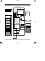
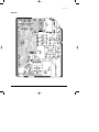
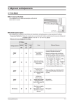
8-3 PCB Inspection Method
8-3-1 Pre-inspection Notices
1. Check if you pulled out the AC power plug when you eliminate the PCB or front panel.
2. Don't hold the PCB side not impose excessive force on it to eliminate the PCB.
3. Don't pull the lead wire but hold the whole housing to connect or disconnect a connector to the PCB.
8-3-2 Inspection Procedure
1. Check connector connection and peeling of PCB or bronze coating pattern when you think the PCB is broken.
2. The PCB is composed of the 3 parts.
1. ● Main PCB Part : MICOM and surrounding circuit, relay, room fan motor driving circuit and control circuit,
sensor driving circuit, power circuit of DC12V and DC5V, and buzzer driving circuit.
1. ● Display part : LED lamp
1. ● Switch part : Switch
8-3-3 Detailed Inspection Procedure
No
Procedure
1
Plug out and pull the PCB
out of the electronic box.
Check the PCB fuse.
1) Is the fuse disconnected? (F701)
2
Supply power.
If the operating lamp
twinkles at this time,
the above 1)~3) have
no relation.
Checking the power voltage.
3
4
58
Press the ON/OFF button
and operate TURBO
mode.
But, exclude the
RESERVE operation.
Inspection Method
Cause
• Overcurrent
• Indoor Fan Motor Short
• AC Part Pattern Short of the MAIN PCB
1) Is the DB71input voltage AC200V~AC240V?
• Power Cord is fault, Fuse open. Wrong
Power Cable Wiring, AC Part is faulty.
2) Is the voltage between both terminals of the
C103 on the 2nd side of the transformer DC12V
±0.5V?
• Switching Trans or Power Circuit is faulty
3) Is the voltage between both terminals of OUT
and GND of IC02(KA78L05) DC5V ±0.5V?
• Power Circuit is faulty, Load Short
Checking the power voltage.
1) Check the voltage of the relay(RY71) coil(IC05 PIN
#11 and GND : 0V, PIN#6 and GND : 5V) during
operation(3 minutes after TURBO operation).
• Relay(RY71) Coil Disconnection, IC05 is
faulty
2) Check the voltage of both terminals of
terminal block 1 and N(1) after 3 minute
operation.: AC220V
• Relay(RY71) Contact is faulty
Press the ON/OFF button. 1) Is the voltage over AC180V being imposed
on terminal #3 and #5 of the fan motor
1. FAN Speed [High]
connector(CN72)?
2. Continuous Operation
• Fan Motor of the indoor is faulty
2) The fan motor of the indoor unit doesn't run.
• Fan Motor Connector(CN72) is faulty
3) The power voltage between terminal #3 and #5
of the connector(CN72) is 0V.
• ASS'Y Main PCB is faulty
• Connection is faulty
Samsung Electronics
DB98_20801A(1)_1
10/8/04 2:39 PM
Page 59
Troubleshooting
8-3-4 Temperature Sensor Feature Conversion Table(Room Temperature Sensor); 103AT
Temperature Sensor Resistance Temperature Sensor Resistance Temperature Sensor Resistance Temperature Sensor Resistance
[˚C]
[˚C]
[˚C]
[˚C]
[Kohm]
[Kohm]
[Kohm]
[Kohm]
70
69
68
67
66
65
64
63
62
61
60
2.229
2.296
2.365
2.437
2.512
2.589
2.669
2.752
2.838
2.928
3.021
49
48
47
46
45
44
43
42
41
40
4.300
4.444
4.594
4.749
4.912
5.080
5.256
5.439
5.630
5.828
29
28
27
26
25
24
23
22
21
20
8.622
8.944
9.281
9.632
10
10.380
10.780
11.200
11.630
12.090
9
8
7
6
5
4
3
2
1
0
18.700
19.480
20.290
21.150
22.050
22.990
23.900
25.030
26.130
27.280
59
58
57
56
55
54
53
52
51
50
3.116
3.216
3.319
3.426
3.537
3.652
3.772
3.897
4.026
4.161
39
38
37
36
35
34
33
32
31
30
6.033
6.246
6.468
6.699
6.941
7.192
7.455
7.729
8.015
8.313
19
18
17
16
15
14
13
12
11
10
12.560
13.060
13.570
14.120
14.680
15.280
15.900
16.550
17.240
17.960
-1
-2
-3
-4
-5
-6
-7
-8
-9
28.470
29.720
31.040
32.430
33.890
35.430
37.050
38.760
40.560
Temperature Sensor Characteristic Curve
Temperature
(˚C)
70
60
50
40
30
At the temperature of 25˚C(10KΩ)
20
10
0
-10
-9
5
10
15
20
25
30
35
40
Resistance Value (Kohm)
Samsung Electronics
59
DB98_20801A(1)_1
10/8/04 2:39 PM
Page 60
8-4 Main Part Inspection Method
Part
Room Temperature Sensor
Room Fan Motor
Breakdown Inspection Method
Measure resistance with a tester
Normal
At the normal temperature 37kΩ~ 8.3kΩ(-7˚C~+30˚C) *Refer to Table 8-4-4.
Abnormal
∞, 0Ω . . . Open or Short
Measure the resistance between terminals of the connector (CN72) with a tester.
Normal
Abnormal
Outdoor Fan Motor
At the normal temperature (10˚C ~ 30˚C)
Compare terminal
Resistance
Remark
Yellow, Blue
404.4Ω ± 10%
Main
Yellow, Red
340Ω ± 10%
Sub
∞, 0Ω . . . Open or Short
Measure the resistance between motor wires with a tester.
Normal
At the normal temperature (10˚C ~ 30˚C)
Compare terminal
Abnormal
Stepping Motor
60
Resistance
Remark
Yellow, Red
360Ω ± 10%
Main
Black, Yellow
328Ω ± 10%
Sub
∞, 0Ω . . . Open or Short
Measure the resistance between the red wire and each terminal wire with a tester.
Normal
About 300Ω at the normal temperature (20˚C ~ 30˚C)
Abnormal
∞, 0Ω . . . Open or Short
Samsung Electronics
DB98_20801A(1)_1
10/8/04 2:39 PM
Page 61
MEMO
Samsung Electronics
61
DB98_20801A(1)_1
10/8/04 2:39 PM
Page 62
9. Exploded Views and Parts List
9-1 Indoor Unit
17
14
6
14-1
15
11
7
14-2
14-3
12
23
14-4
3
16
14-5
18
23-1
14-6
3-1
3-2
19
13
3-4
9
9-2
10
21
23-2
3-3
9-3
18
20
9-1
1
1-1
5
4
2-5
2-4
8
1-3
2-1
2-5-1
2
2-6
2-2
1-2
22
2-3
You can search for the updated part code
number through the ITSELF.
URL : http://itself.sec.samsung.co.kr
62
Samsung Electronics
DB98_20801A(1)_1
10/8/04 2:39 PM
Page 63
Exploded Views and Parts List
■
Parts List
Q'TY
No.
Code No.
1
DB92-00633A
DB92-00633B
DB64-01210A
DB93-02831A
DB63-01103A
DB94-00629A
DB63-01104A
DB61-02049A
DB61-02053A
DB73-00234A
DB94-00062L
DB67-00510A
DB95-20138A
DB93-02960A
DB61-02056A
DB64-01211A
DB93-02806A
DB93-01369A
DB63-01106A
DB63-01107A
DB61-02050A
DB61-02052A
DB93-02804A
DB93-02804B
DB96-03835A
DB96-03951A
DB60-00198A
DB60-00203B
DB96-03834A
DB96-03952A
DB67-60030A
DB94-00455A
DB94-00627A
DB31-00270A
DB94-00626A
DB61-02057A
DB61-02047A
DB61-02048A
DB63-01105A
DB91-00287A
DB93-01383G
DB61-02051A
DB67-00508A
DB70-00514A
DB70-00515A
DB70-00516A
DB93-01549B
DB93-02531S
DB92-00643A
DB90-01829A
DB63-01108A
DB64-01276A
1-1
1-2
1-3
2
2-1
2-2
2-3
2-4
2-5
2-5-1
2-6
3
3-1
3-2
3-3
3-4
4
5
6
7
8
9
9-1
9-2
9-3
10
11
12
13
14
14-1
14-2
14-3
14-4
14-5
14-6
15
16
17
18
19
20
21
22
23
23-1
23-2
Samsung Electronics
Description
ASS'Y PANEL FRONT
ASS'Y PANEL FRONT
PANEL FRONT
ASS'Y SPEAKER
FILTER-PRE
ASS'Y TRAY DRAIN
TRAY DRAIN
BLADE-H
BLADE-V
RUBBER-CAP DRAIN
ASS'Y DRAIN-HOSE
DRAIN-CUFF
ASS'Y MOTOR-STEPPING
ASS'Y DISPLAY
HOLDER DISPLAY
WINDOW DISPLAY
ASS'Y PCB DISPLAY
ASS'Y MODULE PCB
COVER TERMINAL
COVER PCB-DVM
HOLDER EVAP
HOLDER MOTOR
ASS'Y CONTROL IN
ASS'Y CONTROL IN
ASS'Y EVAP TOTAL
ASS'Y EVAP TOTAL
SPACER-EVAP MID
SPACER-EVAP UP
ASS'Y EVAP
ASS'Y EVAP
SPRING-SENSOR
ASS'Y BEARING-RUBBER
ASS'Y-CROSS FAN
MOTOR FAN-IN
ASS'Y BACK BODY
BODY BACK
BUSH BODY LF
BUSH BODY RH
COVER-IONIZER
ASS'Y ELECTRIC-IONIZER
ASS'Y C/W ION
HOLDER-PIPE
CAP SCREW
PLATE-HANGER
PLATE CONTACT
PLATE-CONTROL IN
ASS'Y-CONNECTOR POWER
ASS'Y REMOCON
ASS'Y GRILLE
ASS'Y COVER DISPLAY
COVER DISPLAY
INLAY DISPLAY
Specification
ASS'Y
ASS'Y
HIPS
ASS'Y
PP
ASS'Y
ABS
ABS
PP
CR
ASS'Y
ABS
24BYJ48
ASS'Y
HIPS
HIPS
ASS'Y
ASS'Y
HIPS V0
HIPS
ABS
PP
ASS'Y
ASS'Y
ASS'Y
ASS'Y
PVC
PVC
FP1.3, H-FIN, 2x12
FP1.5, H-FIN, 2x12
STS 301
ASS'Y
ø83 x 719
YDK-20S4D8C-1
ASS'Y
HIPS
HIPS
HIPS
HIPS
ASS'Y
ASS'Y
HIPS
HIPS
SGCC-M, T0.8
SUS 304
SGCC-M
ASS'Y
ARH-1315
ASS'Y
ASS'Y
PC
ACRYL
AS09HPA
AS09HPA
AS12HPA
AS12HPA
(With Melody) (Without Melody) (With Melody) (Without Melody)
1
1
1
1
1
1
1
2
1
1
1
1
1
1
1
1
1
1
1
1
1
1
1
1
1
1
1
1
1
1
1
1
1
1
1
1
1
1
3
1
2
1
1
1
1
1
1
1
1
1
1
1
1
1
2
1
1
1
1
1
1
1
1
1
1
1
1
1
1
1
1
1
1
1
1
1
1
1
1
1
1
1
1
1
1
3
1
2
1
1
1
1
1
1
1
1
1
1
1
1
1
1
2
1
1
1
1
1
1
1
1
1
1
1
1
1
1
1
1
1
1
1
1
1
1
1
1
1
1
1
1
1
1
3
1
2
1
1
1
1
1
1
1
1
1
1
1
1
1
2
1
1
1
1
1
1
1
1
1
1
1
1
1
1
1
1
1
1
1
1
1
1
1
1
1
1
1
1
1
1
3
1
2
1
1
1
1
1
1
1
63
DB98_20801A(1)_1
10/8/04 2:39 PM
Page 64
9-2 Outdoor Unit
21
22-1
22-6
23
22
22-7
22-4
15
22-2
2
22-5
11
24
7
12
3
1
10
14
6
20
18
22-3
17
16
8
19
13
4
5
9
64
Samsung Electronics
DB98_20801A(1)_1
10/8/04 2:39 PM
Page 65
Exploded Views and Parts List
■
Parts List
Code No.
1
6021-000281
NUT-HEXAGON
2
DB67-50063A
FAN-PROPELLER
3
DB31-10058C
MOTOR FAN OUT
220/240V, 50/60Hz
1
1
4
DB90-01524B
ASS'Y CABINET-FRONT
ASS'Y
1
1
5
DB63-00847A
GUARD FAN
PP
1
1
6
DB64-00982A
CABINET-SIDE LF
SECC-P
1
1
7
DB64-00992A
HANDLE-LF
PP
1
1
8
DB90-01525C
ASS'Y-CABI SIDE RH
ASS'Y
1
1
9
DB63-00853A
COVER-CONTROL
ABS
1
1
10
DB90-01295C
ASS'Y-BASE OUT
ASS'Y
1
1
11
DB61-02065A
BRACKET MOTOR
SGCC-M
1
1
12
DB61-02066A
BRACKET-VALVE
GALVANIZED STEEL
1
1
13
DB73-00067A
GROMMET-ISOLATOR
NR
-
3
DB73-00070A
GROMMET-ISOLATOR
NR
3
-
14
DB94-00631A
ASS'Y PARTITION
ASS'Y
1
1
15
DB96-03836A
ASS'Y COND
ø7 FP1.5, LOUVER, 2x24
-
1
DB96-03837A
ASS'Y COND
ø7 FP1.4, LOUVER, 2x24
1
-
16
Description
Specification
Q'TY
No.
AS09HPA
AS12HPA
M6, ZPC, STS410
1
1
AS+G/F 20%, ø405
1
1
G8C124JU1EL
COMPRESSOR
G8C124
-
1
G4A091JU1EL
COMPRESSOR
G4A091
1
-
17
DB63-20002A
GASKET
EPDM
1
1
18
DB63-10165D
COVER TERMINAL
PBT
1
1
19
DB60-30028A
NUT-WASHER
HEX2C M8 ZPC
3
3
20
DB60-30018A
NUT-FLANGE
M5, SM20C
1
1
21
DB71-00093A
BAR-STEEL
HSWR
1
1
22
DB93-02916A
ASS'Y CONTROL OUT
ASS'Y
-
1
DB93-02916B
ASS'Y CONTROL OUT
ASS'Y
1
-
22-1
DB70-00523A
PLATE-CONTROL OUT
SGCC-M
1
1
22-2
DB33-00049A
SOLENOID-ASS'Y
ASS'Y
1
1
22-3
DB35-00028B
RELAY PROTECTOR O/L
RBC12128-12500
-
1
DB35-00028A
RELAY PROTECTOR O/L
RBC12054-12500
1
-
22-4
DB65-40049E
TERMINAL BLOCK
4P
1
1
22-5
DB93-01547D
ASS'Y LEAD WIRE
ASS'Y
1
1
22-6
2501-001237
CAPACITOR-COMP
35uF/450VAC
-
1
2501-001238
CAPACITOR-COMP
40uF/450VAC
1
-
22-7
2301-001375
CAPACITOR-MOTOR
1.5uF/450VAC
1
1
23
DB96-03828A
ASS'Y VALVE 4WAY
ASS'Y
-
1
DB96-03840A
ASS'Y VALVE 4WAY
ASS'Y
1
-
24
DB96-03829A
ASS'Y TUBE CAPILLARY
ASS'Y
-
1
DB96-03839A
ASS'Y TUBE CAPILLARY
ASS'Y
1
-
Samsung Electronics
65
DB98_20801A(1)_1
10/8/04 2:39 PM
Page 66
9-3 Ass'y-Control In : DB93-02804B
■
Parts List
No.
Code No.
1
DB61-02054A
CASE-CONTROL
ABS
1
2
DB65-00103C
ASS'Y-TERMINAL BLOCK
ASS'Y
1
3
DB93-02808B
ASS'Y-MAIN PCB
ASS'Y
1
4
DB93-02809A
ASS'Y-MELODY PCB
ASS'Y
-
5
DB70-00516A
PLATE-TERMINAL LOW
SGCC-M T1.2
1
6
DB61-00171A
HOLDER-WIRE CLAMP
ABS
1
7
6001-000929
SCREW-MACHINE
PH M3 x L22
1
8
6001-001054
SCREW-MACHINE
TH M4 x L10
2
9
DB93-02827A
C/W MAIN TO DISPLAY
ASS'Y
1
10
DB39-00643N
C/W STEP MOTOR UP/DOWN
ASS'Y
1
11
DB32-00020A
ASS'Y-THERMISTOR
4P(103AT)
1
12
DB93-02881A
C/W MELODY TO SPEAKER
ASS'Y
-
13
DB93-02828A
C/W MELODY TO MAIN
ASS'Y
-
SPEAKER WIRE TIE
-
-
14
66
Description
Specification
Q'TY
Remark
Samsung Electronics
DB98_20801A(1)_1
10/8/04 2:39 PM
Page 67
10. Block Diagram
* : OPTION
CONTROLLER
IC-MCU
HEAT EXCHANGER SENSOR
• BLADE CONTROL
• INDOOR FAN MOTOR CONTROL
• COMPRESSOR CONTROL
ROOM TEMPERATURE SENSOR
• OUTDOOR FAN MOTOR CONTROL
SIGNAL
INFRARED SIGNAL
RESET
CIRCUIT
• 4-WAY VALVE CONTROL SIGNAL
• TEMPERATURE CONTROL
• TIMER
• BUZZER CONTROL
• ANION CONTROL
OSCILLATION
CIRCUIT
MODE
(AUTO, COOL, DRY,
FAN, HEAT)
TURBO OPERATION
TEMPERATURE
OPERATION
AUTO CLEAN
TURBO
ENERGY SAVING
TIMER
ANION
FAN SPEED
ZERO
VOLTAGE
DETECT
REMOTE CONTROL
POWER ON/OFF
DISPLAY PART
• COMPRESSOR CONTROL
SIGNAL
• OUTDOOR FAN MOTOR
CONTROL SIGNAL
• 4-WAY VALVE CONTROL
SIGNAL
TRIGGER
SIGNAL
INDOOR FAN MOTOR
SSR
• STEPPING MOTOR
CONTROL SIGNAL
• BUZZER CONTROL SIGNAL
FAN SPEED SELECT
(H/M/L/AUTO)
BLADE-H
MOVING SELECT
ON, OFF TIMER
SELECT/CANCLE
• ANION CONTROL SIGNAL*
• COMPRESSOR DRIVE
• OUTDOOR FAN MOTOR
DRIVE
• 4-WAY VALVE DRIVE
• STEPPING MOTOR DRIVE
TEMPERATURE
SELECT(UP/DOWN)
COMPRESSOR
OUTDOOR FAN MOTOR
4-WAY VALVE
BUZZER
ANION
• BUZZER DRIVE
• ANION DRIVE
STEPPING MOTOR
: BLADE UP/DOWN
SLEEP OPERATION
ANION SELECT
DC 5V
BUZZER CONTROL PART
VOLTAGE REGULATOR
AUTO CLEAN SELECT
SPEA KER
ENERGY SAVING SELECT
DC 12V
SOUND ON/OFF SELECT
DIGITAL
OPTION
SMPS POWER BLOCK
ON/OFF
AC INPUT
Samsung Electronics
67
DB98_20801A(1)_1
10/8/04 2:39 PM
Page 68
11. PCB Diagram
11-1 ASS'Y MAIN PCB : DB93-02482A
■ TOP
68
Samsung Electronics
DB98_20801A(1)_1
10/8/04 2:39 PM
Page 69
PCB Diagram
■ BOTTOM
Samsung Electronics
69
DB98_20801A(1)_1
10/8/04 2:39 PM
Page 70
PCB Diagram
■
Parts List
Location No.
Description
Specification
BD71
DIODE-BRIDGE
DF06S,600V,1A,SMD-4,TP
BZ61
BUZZER-PIEZO
85DB,-,-,2KHZ,-
C101
CAP-AL
15uF,20%,450V,GP,TP,13x20mm,5m
C102
CAP-CHIP
100nF+80-20%,50V,Y5V,TP,2012
C103
CAP-AL
1000uF,20%,25V,GP,TP,10x20.5
C104
CAP-CHIP
100nF,+80-20%,50V,Y5V,TP,2012
C105
CAP-AL
470uF,20%,16V,GP,TP,10x12.5,5
C106
CAP-CHIP
100nF,+80-20%,50V,Y5V,TP,2012
C107
C-CERAMIC,DISC
2.2NF,20%,400V,Y5U,TP,12.5x6mm,10
C108
C-CERAMIC, DISC
2.2NF,20%,400V,Y5U,TP,12.5x6mm,10
C201
CAP-CHIP
100nF,+80-20%,50V,Y5V,TP,2012
C202
CAP-CHIP
10nF,+80-20%,50V,Y5V,TP,2012
C203
CAP-CHIP
10nF,+80-20%,50V,Y5V,TP,2012
C204
CAP-CHIP
100nF,+80-20%,50V,Y5V,TP,2012
C301
CAP-CHIP
100nF,+80-20%,50V,Y5V,TP,2012
C302
CAP-CHIP
100nF,+80-20%,50V,Y5V,TP,2012
C401
CAP-CHIP
1nF,10%,50V,X7R,TP,2012
C402
CAP-CHIP
100nF,+80-20%,50V,Y5V,TP,2012
C403
CAP-CHIP
100nF,+80-20%,50V,Y5V,TP,2012
C404
CAP-CHIP
10nF,+80-20%,50V,Y5V,TP,2012
C405
CAP-CHIP
1nF,10%,50V,X7R,TP,2012
C501
CAP-CHIP
100nF,+80-20%,50V,Y5V,TP,2012
C502
CAP-CHIP
100nF,+80-20%,50V,Y5V,TP,2012
C503
CAP-CHIP
100nF,+80-20%,50V,Y5V,TP,2012
C504
CAP-CHIP
100nF,+80-20%,50V,Y5V,TP,2012
C601
CAP-AL
47uF,20%,50V,GP,TP,6.3x11,5
C801
CAP-CHIP
10nF,+80-20%,50V,Y5V,TP,2012
C901
CAP-CHIP
100nF,+80-20%,50V,Y5V,TP,2012
CD11
DIODE-TVS
ST02D-200,185/200/215V,200W,DO-214
CN43
CONNECTOR-HEADER
BOX,4P,1R,2mm,STRAIGHT,SN
CN44
CONNECTOR-HEADER
BOX,3P,1R,2.5mm,STRAIGHT,SN
CN61
CONNECTOR-HEADER
BOX,5P,1R,2mm,STRAIGHT,SN
CN71
CONNECTOR-HEADER
1WALL,3P,1R,7.92mm,STRAIGHT,SN,BL
CN72
CONNECTOR-HEADER
1WALL,3P,1R,7.92mm,STRAIGHT,SN,WH
CN82
CONNECTOR-HEADER
BOX,3P,1R,2mm,STRAIGHT,WHT
CN91
CONNECTOR-HEADER
BOX,15P,1R,2mm,ANGLE,SN
CR71
C-FILM,MPPF
1.2uF,10%,450Vac,BK,38x18x30,3
D101
DIODE-RECTIFIER
SHG2D,200V,2A,DO-204AC,TP
D701
DIODE-RECTIFIER
UF4007,1KV,1A,DO-41,TP
F701
FUSE
250VAC/3.15A
70
Samsung Electronics
DB98_20801A(1)_1
10/8/04 2:39 PM
Page 71
PCB Diagram
■
Parts List (cont.)
Location No.
Description
Specification
F701
FUSE-CLIP
250V,7.5A,30mohm
FT71
SSU10V-1500
15MH,+50,-30%
IC01
IC-PWM CONTROLLER
TNY266,DIP,8P,300MIL,PLASTIC,-0.3/7
IC02
IC-POSI.ADJUST REG
78L05A,TO-92,3P,-,PLASTIC,4.6
IC04
IC MICOM
S2C848AXZZ-QTRA,-,64,+5V,10MHZ,STM-0309-OA,32
IC05
TR-ARRAY
ULN2003AFW,NPN,7,1W,SOP-16,ST,1000
IC06
TR-ARRAY
ULN2003AFW,NPN,7,1W,SOP-16,ST,1000
IC07
IC-SOURCE DRIVER
7062783AFW,SOL,18P,500MA,TP
IC07
IC-EEPROM
93LC56,128x16Bit,SOP,8P,150MIL,-,2.5V,-
NTC1
THERMISTOR-NTC
22ohm,1.4A,3100K,9.5MW/C,-,7.0-
PC01
PHOTO-COUPLER
TR,130-260%,200mW,DIP-4,ST,PC123YB2J00F
PC02
PHOTO-COUPLER
TR,50-150%,200mW,DIP-4,ST,PC814X1YJ00F
Q201
TR-SMALL SIGNAL
2SC2412K,NPN,200mW,SOT-23,TP,1
Q401
TR-SMALL SIGNAL
2SC2412K,NPN,200mW,SOT-23,TP,1
Q601
TR-SMALL SIGNAL
2SC2412K,NPN,200mW,SOT-23,TP,1
Q602
TR-SMALL SIGNAL
MMST2907A,PNP,200mW,SOT-23,TP,100-
Q603
TR-SMALL SIGNAL
2SC2412K,NPN,200mW,SOT-23,TP,1
R101
R-CHIP
100ohm,5%,1/10W,DA,TP,2012
R102
R-CHIP
2.2K,5%,1/10W,DA,TP,2012
R103
R-COMPOSITION
12Mohm,5%,1/2W,AA,TP,3.4x9mm
R104
R-COMPOSITION
12Mohm,5%,1/2W,AA,TP,3.4x9mm
R105
R-CHIP
470ohm,5%,1/10W,DA,TP,2012
R201
R-CHIP
47Kohm,5%,1/4W,DA,TP,3216
R202
R-CHIP
47Kohm,5%,1/4W,DA,TP,3216
R203
R-CHIP
47Kohm,5%,1/4W,DA,TP,3216
R204
R-CHIP
47Kohm,5%,1/4W,DA,TP,3216
R205
R-CHIP
47Kohm,5%,1/4W,DA,TP,3216
R206
R-CHIP
47Kohm,5%,1/4W,DA,TP,3216
R207
R-CHIP
47Kohm,5%,1/4W,DA,TP,3216
R208
R-CHIP
47Kohm,5%,1/4W,DA,TP,3216
R209
R-CHIP
10Kohm,5%,1/10W,DA,TP,2012
R210
R-CHIP
1Kohm,5%,1/10W,DA,TP,2012
R211
R-CHIP
1Kohm,5%,1/10W,DA,TP,2012
R212
R-CHIP
1Kohm,5%,1/10W,DA,TP,2012
R301
R-CHIP
1Kohm,5%,1/10W,DA,TP,2012
R302
R-CHIP
1Kohm,5%,1/10W,DA,TP,2012
R409
R-CHIP
1Kohm,5%,1/10W,DA,TP,2012
R410
R-CHIP
1Mohm,5%,1/10W,DA,TP,2012
R401
R-CHIP
1Kohm,5%,1/10W,DA,TP,2012
R402
R-CHIP
1Kohm,5%,1/10W,DA,TP,2012
Samsung Electronics
71
DB98_20801A(1)_1
10/8/04 2:39 PM
Page 72
PCB Diagram
■
Parts List (cont.)
Location No.
Description
Specification
R403
R-CHIP
6.8Kohm,5%,1/10W,DA,TP,2012
R404
R-CHIP
1Kohm,5%,1/10W,DA,TP,2012
R405
R-CHIP
330ohm,5%,1/10W,DA,TP,2012
R406
R-CHIP
330ohm,5%,1/10W,DA,TP,2012
R407
R-CHIP
6.8Kohm,1%,1/10W,DA,TP,2012
R408
R-CHIP
6.8Kohm,1%,1/10W,DA,TP,2012
R501
R-CHIP
10Kohm,5%,1/10W,DA,TP,2012
R502
R-CHIP
1Mohm,5%,1/10W,DA,TP,2012
R602
R-CHIP
1Kohm,5%,1/10W,DA,TP,2012
R604
R-CHIP
1Kohm,5%,1/10W,DA,TP,2012
R605
R-CHIP
10Kohm,5%,1/10W,DA,TP,2012
R606
R-CHIP
4.7Kohm,5%,1/10W,DA,TP,2012
R607
R-CHIP
470ohm,5%,1/10W,DA,TP,2012
R608
R-CHIP
470ohm,5%,1/10W,DA,TP,2012
R609
R-CHIP
560ohm,5%,1/10W,DA,TP,2012
R610
R-CHIP
1Kohm,5%,1/10W,DA,TP,2012
R611
R-CHIP
1Kohm,5%,1/10W,DA,TP,2012
R908
R-CHIP
10Kohm,5%,1/10W,DA,TP,2012
R909
R-CHIP
4.7Kohm,5%,1/10W,DA,TP,2012
RY71
RELAY-POWER
12VDC,0.9W,25000MA,SPST,20MS,10MS
RY72
RELAY-MINIATURE
12VDC,200MW,3000MA,1FORMA,10MS,5MS
RY73
RELAY-MINIATURE
12VDC,200MW,3000MA,1FORMA,10MS,5MS
SS71
SSR
12Vdc,-,2A,1mS,1mS
ST11
SW-TRANS
TRANS SWITCHING;JT1916-09,-,200V~240V,-,-
VA71
VARISTOR
560V,2500A,17.5x7.5mm,TP
X501
RESONATOR-CERAMIC
10MHZ,0.5%,BK,8x3x5.5mm
XC71
C-FILM,MPPF
100nF,10%,275V,BK,24.5x6x14.5
XC72
C-FILM,MPPF
100nF,10%,275V,BK,24.5x6x14.5
ZD11
DIODE-ZENER
BZX84C3V6,3.6,350mW,SOT-23,TP
ZD12
DIODE-ZENER
BZX84-C11,10.4-11.6V,350MW,SOT-23,TP
72
Samsung Electronics
DB98_20801A(1)_1
10/8/04 2:39 PM
Page 73
11-2 ASS'Y DISPLAY PCB : DB93-02806A
■
Parts List
No.
Description
Specification
Q'TY
Remark
1
SNA
1
ASS'Y DISPLAY REFLECTOR
2
PCB-DISPLAY
FR-4 T1.6
1
SNA
3
TACT SWITCH
KPT-1105A
1
SNA
4
RESISTOR
200ohm, 2W
4
SNA
5
CONNECTOR WIRE
3P
1
SNA
6
CONNECTOR
SMW200-15P
1
SNA
Samsung Electronics
73
DB98_20801A(1)_1
10/8/04 2:39 PM
Page 74
11-3 ASS'Y MODULE PCB : DB93-01369A
■
Parts List
No.
74
Description
Specification
Q'TY
Remark
1
PCB MODULE
FR1 T1.6
1
SNA
2
CONNECTOR-HEADER
BOX, 3P, 1R, 2mm, ANGLE, SN
1
SNA
3
C-CERAMIC, MLC-AXIAL
1nF, 10%, 50V, Y5P, TP, 1.9 x 3.5, -
1
SNA
4
DIODE-SWITCHING
1N4148, 100V, 200mA, DO-35, TP
1
SNA
5
C-CERAMIC, MLC-AXIAL
100nF, +80-20%, 50V, Y5V, TP, 3.5 x 1
1
SNA
6
MODULE
346HF12N
1
SNA
Samsung Electronics
DB98_20801A(1)_1
10/8/04 2:39 PM
Page 75
12. Wiring Diagram
12-1 Indoor Unit
Code No : DB98-20360A
This Document can not be used without Samsung's authorization.
Samsung Electronics
75
DB98_20801A(1)_1
10/8/04 2:46 PM
Page 76
12-2 Outdoor Unit
C1
MOTOR CAPACITOR
FM1
FAN MOTOR
C2
COMP CAPACITOR
O.L.P
OVER LOAD PROTECTOR
Code No : DB98-15123A
This Document can not be used without Samsung's authorization.
76
Samsung Electronics
DB98_20801A(1)_1
10/8/04 2:47 PM
Page 77
13. Schematic Diagram
13-1 Indoor Unit
This Document can not be used without Samsung's authorization.
Samsung Electronics
77
DB98_20801A(1)_1
10/8/04 2:47 PM
Page 78
MEMO
78
Samsung Electronics
DB98_20801A(1)_1
10/8/04 2:47 PM
Page 79
MEMO
Samsung Electronics
79
DB98_20801A(1)_1
10/8/04 2:47 PM
Page 80
MEMO
80
Samsung Electronics
DB98_20801A(1)_co
10/8/04 2:33 PM
Page 2
ELECTRONICS
This Training Manual is a property of Samsung Electronics Co., Ltd.
Any unauthorized use of Manual can be punished under applicable
International and/or domestic law.
© Samsung Electronics Co., Ltd. Oct. 2004.
Printed in Korea.
Code No. DB98-20801A(1)