1
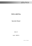
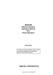
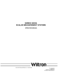
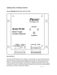
ELECTRONIC COUNTERS, POWER METERS, VOLTMETER
POWER METER
ML4803A
100 kHz to 90 GHz
For Measuring Power in Quasi-Millimeter and Millimeter Wave Bands
4
GPIB
The ML4803A consists of an indicator, which displays the detected
electric signals as the power, and power sensors, which detect power and convert it to electric signals. Several types of power sensors
are provided for accurately measuring power in a frequency range of
100 kHz to 90 GHz. The ML4803A has various functions to meet all
power measurement requirements, from low frequency to super-high
frequency such as the millimeter waveband.
Features
• Abundant functions
(1) Three measurement modes
The ML4803A can measure absolute values in units of “W” or “dBm”
in addition to relative values in units of “dB” or “%” . When return loss
is measured in absolute value measurement, VSWR can also be displayed.
(2) Automatic sensor sensitivity correction
The sensitivity of coaxial power sensor is corrected automatically by
a one-touch operation using the built-in calibration oscillator.
• Excellent operability and efficient measurement with memory
function
(1) The corrections required in measurements (calibration coefficient,
corrected value of attenuation or gain and reference value in relative measurements) can be easily set using the rotary encoder.
(2) Since the amount of correction for 30 points corresponding to
measured frequencies can be stored beforehand, it need not be
set each time the measured frequency changes. This function improves measurement efficiency.
(3) The amount of correction set is retained even when the power
supply is turned off.
• Three power supplies
The ML4803A can be operated on AC, DC, or batteries and can
therefore be used anywhere.
• Super-wide coaxial-type amorphous sensors
(1) Supper-wide band: 100 kHz to 32 GHz
(2) Wide dynamic range: –30 to +20 dBm
(3) Low VSWR and high response speed
(4) 75 Ω power sensor is provided
The amorphous detection element is field-replaceable.
• Diode sensor suitable for low-level and wide-band measure-
ments
(1) Wide band: 100 kHz to 26.5 GHz
(2) Low-level measurement: –70 to –20 dBm
(3) Compact and lightweight
(4) 75 Ω power sensor
• Quasi-millimeter and millimeter waves can also be measured.
The conventional waveguide-type power sensors can be used by connecting them to the ML4803A using adapter MA4002A/B.
For product ordering information, see pages 4-7.
www.anritsu.com
233
ELECTRONIC COUNTERS, POWER METERS, VOLTMETER
Specifications
• ML4803A indicator
Frequency range
100 kHz to 90 GHz
For high level: MA4701A, MA4703A, MA4705A, MA4601A, MA4603A
For low level: MA4702A, MA4704A, MA4602A, MA4604A
MP737A, MP738A, MP712A[ ] , MP713A[ ] (used with MA4002A Adapter)
MP714A[ ], MP715A[ ], MP716A[ ], MP717A[ ] (used with MA4002B Adapter)
W, dBm, or dB (REL) can be selected. 4-digit digital display (20% over range is equipped)
Compact analog indicator is built-in (values cannot be used.)
Coaxial types
Sensor
For quasi-millimeter and
millimeter waves
Display
Calibration coefficient, offset value, and
reference level setting
Calibration coefficient: 0 to 10 dB (accuracy: 0.01 dB)
Offset value: 0 to ±99.99 dB (accuracy: 0.01 dB)
Reference level: –99.99 to +99.99 dBm (accuracy: 0.01 dB)
Power range
MA4701A/4703A/4705A/4601A/4603A full-scale values: –20, –10, 0, +10, +20 dBm (10 µW to 100 mW)
MA4702A/4704A/4602A/4604A full-scale values: –60, –50, –40, –30, –20 dBm (1 nW to 10 µW)
MP series sensors full-scale values: –20, –10, 0, +10, +20 dBm (10 µW to 100 mW)
Automatic or manual (range hold) can be selected.
When manual is selected, an arbitrary range can be set unrelated to input levels.
Selected range (when range is held) is displayed on range lamps 1 to 5.
An under range or over range is also displayed.
Range switching
Range display
Accuracy
Accuracy (at indicator)
WATT mode: ±0.5%, dBm mode: ±0.02 dBm, dB (REL) mode: ±0.02 dB
Zero adjustment
Automatically performed by pressing push-button key
Zero setting
MA series sensors: ±0.5% of full scale (typical value) at the highest sensitivity range (range 1)
MP series sensors: ±1.0% of full scale (typical value) at the highest sensitivity range (range 1)
Zero shift between each
range
MA series sensors: ±0.2% of full scale after zero set at the highest sensitivity range
MP series sensors
±0.8% of full scale: Range 2 after zero set at the highest sensitivity range
±0.5% of full scale: Range 3 to 5 after zero set at the highest sensitivity range
Calibration oscillator
50 MHz calibration oscillator is built in. Output connector: N (J)
Output power: 1.00 mW (0 dBm)
Accuracy: Set to within 0.7% at factory (NIST traceable) ±1.2% worst case for one year
Averaging
4 sample rates can be selected.
Low-level TTL (0 to +0.25 V) in zero set mode
High-level TTL (5 ±0.25 V) when zero set mode is cancelled
DC voltage proportional to indicated value is output (1 V in full-scale display).
Output impedance: 1 kΩ, Output connector: BNC
RF blanking output
Recorder output
Remote-control
GPIB is standard.
Front panel functions other than the power switch can be controlled externally.
SH1, AH1, T5, L4, SR1, RL1, PP0, DC1, DT0, C0
Memory function
Up to 30 frequencies, calibration coefficient, offset value, and reference level data combinations can be stored.
Power
supply
+10
–15 %,
50/60 Hz, <20 VA
AC power supply
100 V
DC power supply
+7 to +12 V, ≤13 VA
External battery pack
Continuous operation with MZ5003A Battery Pack: 5 hours
0˚ to 50˚C
Operating temperature
Dimensions and mass
213 (W) x 88 (H) x 250 (D) mm, ≤3 kg
EMC*1
EN55011: 1991, Group 1, Class A
EN50082-1: 1992
Safety
EN61010-1: 1993 (Installation Category ΙΙ, Pollution Degree ΙΙ)
*1: Electromagnetic Compatibility
• Coaxial-type power sensors
Amorphous power sensor
Model
Frequency range
MA4701A
MA4703A
MA4705A
MA4601A
MA4603A
10 MHz to 18 GHz
50 MHz to 26.5 GHz
50 MHz to 32 GHz
100 kHz to 5.5 GHz
100 kHz to 2 GHz
50 Ω
Nominal impedance
Maximum VSWR
1.4 (10 to 30 MHz)
1.18 (30 to 50 MHz)
1.1 (50 MHz to 2 GHz)
1.18 (2 to 12.4 GHz)
1.28 (12.4 to 18 GHz)
Measured power range
–30 to +20 dBm (1 µW to 100 mW)
Maximum input power
300 mW in average
Linearity
±3% in only +10 to +20 dBm range
Input connector
Dimensions and mass
234
1.15
1.10
1.15
1.20
1.25
(50 to 100 MHz)
(0.1 to 2 GHz)
(2 to 12.4 GHz)
(12.4 to 18 GHz)
(18 to 26.5 GHz)
1.15
1.10
1.15
1.20
1.25
1.50
75 Ω
(50 to 100 MHz)
(0.1 to 2 GHz)
(2 to 12.4 GHz)
(12.4 to 18 GHz)
(18 to 26.5 GHz)
(26.5 to 32 GHz)
N
APC-3.5
34 (W) x 25 (H) x 98 (L)
mm, ≤200 g
34 (W) x 25 (H) x 87 (L) mm, ≤200 g
www.anritsu.com
1.3
1.2
1.1
1.2
(100 to 300 kHz)
(0.3 to 1 MHz)
(1 MHz to 4 GHz)
(4 to 5.5 GHz)
N
1.4 (100 to 300 kHz)
1.15 (300 kHz to 2 GHz)
NC
34 (W) x 25 (H) x 98 (L) mm, ≤200 g
For product ordering information, see pages 4-7.
ELECTRONIC COUNTERS, POWER METERS, VOLTMETER
Diode power sensor
Model
MA4702A
MA4704A
MA4602A
MA4604A
10 MHz to 18 GHz
50 MHz to 26.5 GHz
100 kHz to 5.5 GHz
100 kHz to 2 GHz
1.4 (10 to 30 MHz)
1.15 (30 MHz to 4 GHz)
1.2 (4 to 8 GHz)
1.3 (8 to 18 GHz)
1.15 (50 MHz to 4 GHz)
1.2 (4 to 8 GHz)
1.3 (8 to 18 GHz)
1.54 (18 to 26.5 GHz)
Frequency range
50 Ω
Nominal impedance
Maximum VSWR
Measured power range
–70 to –20 dBm (0.1 nW to 10 µW)
Maximum input power
200 mW in average/peak, 0 Vdc
Linearity
±2% in only –30 to–20 dBm range
Input connector
N
Dimensions and mass
75 Ω
1.3 (100 to 300 kHz)
1.15 (300 kHz to 3 GHz)
1.2 (3 to 5.5 GHz)
1.4 (100 to 300 kHz)
1.2 (300 kHz to 2 GHz)
N
NC
APC-3.5
34 (W) x 25 (H) x 98 (L) mm, ≤200 g 34 (W) x 25 (H) x 87 (L) mm, ≤200 g
34 (W) x 25 (H) x 98 (L) mm, ≤200 g
• Waveguide sensors
For quasi-millimeter waveband
Model
MP737A
MP738A
MP712A[ ]
MP713A[ ]
Frequency range
17 to 22 GHz
21.7 to 33 GHz
18 to 26.5 GHz
26.5 to 40 GHz
Maximum VSWR
1.6
1.5
1.6
Measured power range
–30 to +20 dBm (1 µW to 100 mW)
Maximum input power
+22 dBm (160 mW)
Linearity error
±3% only +10 to +20 dBm range
4
MP714A[ ]
33 to 50 GHz
1.5
Dimensions and mass
52ø x 103L mm, ≤450 g
52ø x 78L mm, ≤700 g
Required adapter type
MA4002A
MA4002B
For millimeter waveband
Model/Order No.
MP715A[ ]
MP716A[ ]
MP717A[ ]
Frequency range
40 to 60 GHz
50 to 75 GHz
60 to 90 GHz
Maximum VSWR
1.4
Measured power range
–30 to +20 dBm (1 µW to 100 mW)
MA4002B
Maximum input power
+22 dBm (160 mW)
J0364
Linearity error
±3% in only +10 to +20 dBm range
Dimensions and mass
52ø x 78L mm, ≤700 g (including cord)
Required adapter type
MA4002B
Model
J0365
MP47A
Please select the type of flanges from the below and put its number in the mark [ ].
Blank: JIS flange, 1: MIL flange, 4: UG flange
Ordering information
Please specify model/order number, name, and quantity when ordering.
Model/Order No.
MA4001A
MA4002A
J0064B
Name
ML4803A
Main frame
Power Meter
J0370A
J0017
F0018
W0081AE
W0081BE
Standard accessories
Sensor connecting cord, 1.5 m:
Power cord, 2.5 m:
Fuse, 0.5 A:
ML4803A operation manual:
ML4803A service manual:
MA4601A
MA4603A
MA4701A
MA4703A
MA4705A
MA4602A
MA4604A
MA4702A
MA4704A
MP712A[ ]
MP713A[ ]
MP714A[ ]
MP715A[ ]
MP716A[ ]
MP717A[ ]
MP737A
MP738A
Sensors
Amorphous Power Sensor (coaxial-type)
Amorphous Power Sensor (coaxial-type)
Amorphous Power Sensor (coaxial-type)
Amorphous Power Sensor (coaxial-type)
Amorphous Power Sensor (coaxial-type)
Diode Power Sensor (coaxial-type)
Diode Power Sensor (coaxial-type)
Diode Power Sensor (coaxial-type)
Diode Power Sensor (coaxial-type)
Waveguide Type Sensor*1
Waveguide Type Sensor*1
Waveguide Type Sensor*1
Waveguide Type Sensor*1
Waveguide Type Sensor*1
Waveguide Type Sensor*1
Waveguide Type Sensor*1
Waveguide Type Sensor*1
MP721D
J0077
J0063
J0078
J0395
J0064A
J0064C
J0366
1
1
1
1
1
pc
pc
pc
copy
copy
J0368
J0632A
J0632B
*1: Refer to the data sheet for ML4803A. Specify waveguide type when ordering.
For product ordering information, see pages 4-7.
J0367
J0633A
J0633B
J0633C
J0633D
J0633E
J0633F
J0633G
J0633H
J0369
B0183
B0184
B0185
B0186
J0370C
J0370E
J0370G
MZ5003A
J0371
J0008
www.anritsu.com
Name
Optional accessories
Range Calibrator (for indicator full-scale calibration)
Sensor Adapter for quasi-millimeter wave
(for MP712A/713A/737A/738A)
Sensor Adapter for millimeter wave
(for MP714A/715A/716A/717A)
APC-3.5 to N conversion connector
(required for MP4703A/4704A/4705A)
NC-J•N-P conversion connector for sensitivity calibration
(required for MA4603A/4604A)
Attenuator for sensitivity calibration (30 dB, required for
MA4602A/4604A/4702A/4704A)
Fixed Attenuator (20 dB, N-type, 2 W, DC to 12.4 GHz)
Fixed attenuator (20 dB, N-type, 2 W, DC to 18 GHz)
Fixed attenuator (30 dB, N-type, 10 W, DC to 12.4 GHz)
Fixed attenuator (20 dB, N-type, 10 W, DC to 18 GHz)
Fixed attenuator (30 dB, N-type, 30 W, DC to 8.6 GHz)
7 GHz band coaxial waveguide connector
(5.8 to 8.2 GHz, N-J to BRJ-7)
10 GHz band coaxial waveguide connector
(10.0 to 15.0 GHz, N-J to BRJ-120)
10 GHz band coaxial waveguide connector
(8.2 to 13.0 GHz, N-J to BRJ-10)
18 GHz band coaxial waveguide connector
(17.7 to 21.2 GHz, SMA-J to FUBR180)
22 GHz band coaxial waveguide connector
(18 to 26.5 GHz, APC-3.5-J to UG-5971U)
30 GHz band coaxial waveguide connector
(26.5 to 34 GHz, APC-3.5-J to UG-5991U)
18 GHz band coaxial waveguide connector
(17.7 to 22 GHz, SMA-J to FUBR180)
26 GHz band coaxial waveguide connector
(22 to 33 GHz, K-J to FUBR260)
Conversion connector (NC-J • BNC75-J)
Conversion connector (NC-J • BNC75-P)
Conversion connector (NC-P • BNC75-J)
Conversion connector (NC-P • BNC75-P)
Conversion connector (NC-P • SP3C-J)
Conversion connector (NC-J • SP3C-P)
Conversion connector (NC-P • SP3C-J)
Conversion connector (NC-P • SP3C-P)
Taper waveguide: WRJ-320 (FUBR320)/WRJ-260 (FUBR260)
Rack mount kit-1 (for one ML4803A)
Rack mount kit-2 (for two ML4803A)
Carrying bag
Protective front cover
Sensor cord, 2.5 m (for extension)
Sensor cord, 5 m (for extension)
Sensor cord, 10 m (for extension)
Battery Power Supply (for DC operation)
DC power cord (for +7 to +12 V power supply)
GPIB cable, 2 m
235
ELECTRONIC COUNTERS, POWER METERS, VOLTMETER
List of power meter components
When ordering sensors, refer to the following figure to order required
components that are sold separately.
MA4701A/4601A Coaxial
Sensor (connector: N)
MA4703A/4705A Coaxial
Sensor (connector: APC-3.5)
J0364 conversion
connector
(APC-3.5•N)
(sold separately)
ML4803A Power Meter
MA4603A Coaxial Sensor
(75 Ω)
J0365 conversion
connector (for sensitivity calibration, NCJ•N-P)
(sold separately)
Sensor connection cord
MA4702A/4602A
Coaxial Sensor (for low level,
connector: N)
MP47A 30 dB Attenuator
(for sensitivity calibration)
(sold separately)
MA4704A Coaxial Sensor (for
low level, connector: APC-3.5)
MA4604A Coaxial Sensor
(for low level, connector: NC)
MZ5003A Battery Power Supply
J0364 conversion connector (APC-3.5•N)
MP47A 30 dB
Attenuator (for sensitivity calibration)
(sold separately)
(sold separately)
J0365 conversion connector (for sensitivity
calibration, NC-J•N-P)
MP47A 30 dB
Attenuator (for sensitivity calibration)
(sold separately)
(sold separately)
MA4002A Adapter
(sold separately)
MP737A/738A/712A/
713A[ ] Quasi-Millimeter
Wave Sensor
MA4002B Adapter
(sold separately)
MP714A[ ] /715A[ ] /
716A[ ] /717A[ ]
Millimeter Wave Sensor
MA4001A Range Calibrator
236
www.anritsu.com
For product ordering information, see pages 4-7.