1
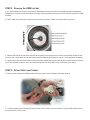
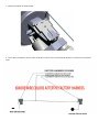
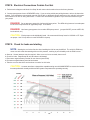
INNOVATIONS
PLEASE READ INSTRUCTIONS CAREFULLY
BEFORE STARTING INSTALLATION
Congratulations on your purchase of the LX fuel module from Fore Innovations. This fourth generation product is the
culmination of all our experience with in-tank fuel systems. Please take a few moments to familiarize yourself with this
manual in order to properly install this product.
Due to the sensitive nature of this product and the possibility of installation error, we recommend this product for off-road
use only. Exercise all safety precautions with any tools/chemicals/other devices that you use during installation. If you
encounter any unfamiliar tasks during installation, allow an experienced professional to complete the installation.
This product requires a thorough understanding of all components of a high performance fuel system to implement and
install correctly. By attempting to install or installing this product, Fore Innovations, LLC does not accept responsibility for
personal injury or property damage. If you encounter any questions or concerns during installation, please contact us at
386-767-3817.
This system supports the use of high performance fuel pumps that provide over four times the performance of the OEM
fuel pump. Properly upgraded wiring and plumbing must be used. The actual requirements may vary drastically depending on the particular application and may require additional parts to complete installation. Please contact us if you have
any questions regarding the support requirements of this product.
Please reference the following boldface terms during these instructions by their significance:
DANGER:
This term is used when immediate or long term human safety may be at risk, as well as safety of the
product and your vehicle or surrounding environment (i.e. installation facility)
CAUTION: This term is used when product or vehicle component damage may be at risk
NOTE(S): This term is used for specific information regarding the product or installation that should be given additional consideration by the customer or installer.
Please reference the following diagram during installation for terminology.
DANGER: Gasoline and gasoline vapors are hazardous to your health and safety.
Exercise extreme caution
by wearing eye protection and working in a well ventilated area. Ensure that all sources of flame or spark are
eliminated from the working area while gasoline vapors are present.
Your fuel lines are under pressure. Please exercise care when relieving pressure.
Gasoline soaked rags may catch fire when stored in confined areas EVEN WITHOUT exposure to spark. Allow
gasoline soaked rags to dry in a well ventilated environment before disposal.
At all times during installation and testing, keep an appropriate fire extinguishing device accessible.
CAUTION: If you damage the wire seal or you need the wires replaced, contact Fore Precision for an assessment. Special chemicals and procedures are required to properly and safely repair the wire seal.
PACKAGE CONTENTS:
Fore Innovations LX Fuel Hat (fuel pumps will be preinstalled if purchased with hat)
Hardware Package:
4 x shrink wrap segments (fuel resistant)
4 x crimp connectors
1 x large hose clamp
1 x small hose clamp
2 x tie wraps (fuel resistant)
SCOPE OF THIS DOCUMENT:
These are not all-inclusive instructions for upgrading a fuel system. These instructions cover the installation of ONLY the
Fore Innovations fuel hat for the LX/LC platform. Since the scope of this installation can require a wide range of additional
parts, we cannot cover them in this manual. Please consult the individual manuals for installation of the individual components. This product requires the installer have general knowledge of installation and operation of all components of a fuel
system. However, if you have particular questions regarding any aspect of your fuel system, please contact us.
CONFIGURATIONS AND INSTALLATION OPTIONS
RETURNLESS CONFIGURATION
This configuration is recommended for <700 rwhp applications. (or less than 12 psi) In this case, the OEM feed line is
adequate and does not require an upgrade. Either Walbro GSS342 or GT Supercar fuel pumps may be used. The feed
and return ports on the top of the fuel hat will need to be plugged. (use P/N 200015K to plug the feed and return ports) In
a returnless configuration, we do NOT recommend the use of the DCSS405 pumps due to the small OEM fuel pressure
regulator.
RETURN CONFIGURATION WITH STATIC REGULATION
This configuration is recommended for high performance naturally aspirated or nitrous applications. In this case, the OEM
fuel pressure regulator and feed line is disabled (use P/N 14-901) and an external regulator is used with a filter plug (use
P/N 100037) in the manfold reference port. The fuel pressure will be maintained at the set pressure regardless of the
manifold vacuum.
RETURN CONFIGURATION WITH BOOST (MANIFOLD) REFERENCE
This configuration is recommended for high performance forced induction applications so that the pressure difference
across injectors is kept constant despite the change in manifold vacuum/pressure. The OEM fuel pressure regulator and
feed line is disabled, (use 14-901) an external fuel pressure regulator is used, but the manifold reference port on the regulator is connected to the intake manifold. The fuel pressure will be set to an initial “base” value, and the fuel pressure will
be modulated at a 1:1 ratio as manifold pressure/vacuum varies.with the battery terminals.
NOTES ON COMPONENT USAGE
Do not use any other fuel pumps other than what is supplied by Fore Innovations. We use geniune Walbro (TI Automotive) fuel pumps. Several [domestic and foreign] companies have attempted to copy these pumps and do not meet our
reliability and performance expectations.
Only use Fore Innovations F1i, F2i, or F4i fuel pressure regulators. Many other aftermarket regulators are not sized properly to accomodate a Fore fuel hat.
DANGER: Do not use any fuel line other than recommended by Fore Innovations. Specifically, do not use any
“push-lock” or “socketless” fuel line on pressurized fuel lines. (use is acceptable on return lines, which are not pressurized)
MAJOR OPTIONS / ACCESSORIES:
15-100: F1i adjustable fuel pressure regulator
15-200: F2i adjustable fuel pressure regulator
15-400: F4i adjustable fuel pressure regulator
16-100: 10 micron fuel filter
11-101/102: Hemi fuel rails for 5.7/5.9/6.2/6.4
23-901: FC2 Dual Channel Controller
Fittings, and other accessories as required by the installer
SPECIALTY ITEMS REQUIRED FOR INSTALLATION:
Heat gun
Crimp tool (for 18 gauge wire)
Factory service manuals
Basic hand tools
STEP 1: Prepare the car and work area for installation.
a. Drive car or drain fuel until the fuel level is approximately one quarter tank of fuel remaining. Higher levels of fuel may
cause a significant fuel spill when the tank is opened.
b. Park car in an area that is well protected from wind, dust, dirt, etc. The intent is to keep blowing dirt and debris from
entering the exposed fuel system.
c. Set up a ventilation fan to PULL harmful and dangerous gasoline fumes from the work area. Gasoline vapors are
heavier than air and will stay close to the ground, so keep this in mind if you are planning to work under the car while supported by jack stands. (i.e. running fuel line, wires, etc).
d. Prepare a clean work area on a workbench for disassembly of the factory fuel hat and assembly of the Fore Precision
fuel hat.
e. Disconnect only the negative terminal on battery and position the loose wire so that it cannot accidentally make contact
f. Relieve pressure on fuel system by following the procedure in the factory service manual.
STEP 2: Remove the OEM fuel hat
a. It is not necessary to remove the fuel tank for installation since the fuel hats are accessible through the passenger
comparment. Remove the rear seat bench according to the procedure in the factory service manual to expose the OEM
fuel hats.
b. FIRST, label driver side fuel hat car side wiring harness as follows, THEN cut off black plastic connector.
c. Remove the lockring on the driver side fuel hat according to the factory service manual, then partially lift the fuel hat
out of the tank. Disconnect all in-tank connections before separating fuel hat from vehicle. Set on prepared workbench.
d. Observe there are three hoses and two wires remaining INSIDE the fuel tank after the driver side fuel hat is removed.
Cut off the electrical connector on the two wires and replace with the included crimp connectors (3/16” male)
STEP 3: Driver Side Level Sender
a. Remove level sender from OEM assembly as shown: (wires may be different colors than picture)
b. Cut level sender wires so that at least three inches of wire remain on the level sender. Crimp included male connectors on wire ends. (3/16” male)
c. Install level sender as shown below:
d. Due to the inconsistency of wire colors inside the fuel tank, refer to the following diagram to connect the level sender
wires:
NOTES: (Regarding wiring)
a. Use supplied shrink wrap over level sender wires. Shrink wrap is not intended to seal the connection, but only to
prevent the level sender wires from contacting each other, causing erratic level sender readings and/or alarm codes.
b. Level senders are not individually polarity sensitive, so they cannot be hooked up “backwards.”
c. The car’s computer distinguishes fuel levels between the driver/passenger side, so it is critical that the wiring diagram
be followed.
c. Position pump and level sender wires to prevent interference with the level sender arm. Use included tie wrap if necessary.
STEP 4: Install Fuel Hat
a. Install hose clamps to venturi discharge line and internal return line ends through driver side tank opening. It may be
required to loosen clamps to slip over hose ends.
c. Place assembly near tank opening and connect passenger side sender wires. Carefully use a heat gun to shrink the
supplied shrink wrap over the crimped level sender connectors.
d. Lower assembly into tank and connect venturi discharge and internal return lines to appropriate their respective fittings.
Tighten hose clamps.
e. Reinstall lockrings according to the factory service manual.
STEP 5: Fuel Connections
RETURNLESS CONFIGURATIONS ONLY:
Install -8 o-ring plugs in feed and return ports at top of fuel hat.
RETURN CONFIGURATIONS ONLY:
a. Install 90 degree fittings and orient so that both the feed and return fittings point towards the REAR driver side wheel.
NOTE:
Use low profile 90 degree swivel fittings on ports at top of fuel hat. (use PN 200030, AN-8 to ORB8
male 90 degree fitting)
NOTE:
It may be necessary to loosen the fuel tank to feed fuel lines to fuel hat. Follow instructions outlined in
the factory service manual for removing and reinstalling fuel tank to accomplish. Do not lower more than necessary; it is possible to disconnect the tank vent and/or EVAP lines located between the fuel tank and sheetmetal.
b. Connect fuel lines and ensure fuel tank is secured according to the factory service manual.
STEP 8: Electrical Connections Outside Fuel Hat
a. Reference the diagram and labels from Step 3d and connect level sender wires to the factory harness.
b. Connect pump power wires to UPGRADED wires. If you are using a third party wiring harness, refer to the instruction
manual. Fore Innovations recommends controller P/N 23-901 to adequately power and protect your vehicle’s fuel system.
See manual for 23-901 for wiring instructions. Contact Fore Innovations for guidance if you are unsure about wiring to
your pumps.
DANGER: Do not attempt to power this fuel hat with factory wires. The OEM wiring harness is not adequate
for the current requirements of upgraded pumps. Fire hazard!
DANGER: Use factory pump power wire to retain OEM pump control. (pumps ON/OFF, prerun at KEY ON,
inertia switch, etc.)
CAUTION:
Each pump must be individually fused. We recommend 20 amp fuses for GSS342 or GT Super
car pumps. Use 25 amp fuses on each DCSS405 fuel pump.
STEP 9: Check for leaks and starting
NOTE:
Starting the car for the first time after installing the fuel hat may be difficult. The vehicle’s ECM may
revert to a safe mode after starting with zero fuel pressure, resulting in poor drivability until the ECM is reset.
a. Start car. Several attempts may be required. Allow car to run for ten seconds, then turn off.
b. Check for leaks. Repeat step 9a until all leaks are eliminated.
c. Disconnect negative battery terminal for ten minutes (reset ECM)
d. Reconnect negative battery terminal and restart.
e. Take the car on a short drive and continue to monitor for fuel leaks.
CAUTION:
A custom tune from a shop with a reputable tuning record is MANDATORY to ensure the installation was performed correctly and that all fuel system components are operating correctly.
Please take a moment are read through our FAQ section for this product:
Q: I noticed that your fuel hat does not have a “basket” to keep fuel surrounding the pumps like the OEM fuel hat. Why
does Fore Innovations omit this feature?
A: Through extensive testing, we have found that the basket is not required on the LX/LC fuel tank, and actually a restriction on our high capacity modules. The basket is included on the OEM hat as part of the fuel tank supplier’s standard
product. We found through testing that retaining the basket is actually counterproductive in two pump configurations
because the volume of the basket is too small (limited by tank height and opening diameter), and refill provisions are inadequate. (less than 8 seconds of fuel available in a triple pump assembly with a basket) Our fuel hats may be operated
down to the fuel gage indicating “empty” with no adverse affects.
Q: Can I operate this product in E85?
A: Yes. Ensure the other components in your fuel system are compatible with E85 as well. Often, E85 requires more
frequent filter changes.
Q: What kind of fuel filter do I need to put in line after the fuel hat?
A: A 10 micron filter is needed to protect your fuel injectors. The included prefilters are 40 micron elements to protect
the pumps. We recommend our F10 filter PN 16-100
Q: How does a Fore Innovations fuel hat compare with an external fuel pump?
A: The Fore Innovations dual DCSS405 fuel hat outperforms nearly every external fuel pump on the market. In the back
of this manual, we have included a performance chart in three different units to assist in any comparisons.
Q: Does the fuel hat interfere with the crossover function of the OEM fuel hat?
A: Our fuel hat does not interfere with the OEM crossover function.
Q: What value should I set my base fuel pressure?
A: You should set your fuel pressure at 40psi in a boost referenced, return style fuel system to allow pressure headroom
for boost, maximize pump capability, and to reduce workload on the fuel pumps. Myths regarding the vehicle’s computer
“preferring” a specific fuel pressure are incorrect as the vehicle has no sensor to report fuel pressure to the computer.
The OEM system runs at ~60psi to prevent vapor lock in the fuel rails in the OEM returnless fuel system. Many tuners
prefer to maintain this high base pressure in a return system because their tuning development does not accomodate
lower fuel pressures.
Q: What size fuel lines should I run?
A: -8 feed and -8 return are adequate for our LX fuel hat with the largest pumps. (DCSS405 pumps)