1
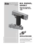
Air Lift PERFORMANCE ™ Kits 75677/78635 Audi A6 C6 Platform Rear Application MN-804 • (021506) • ERN 8261 (With and Without Shocks) INSTALLATION GUIDE For maximum effectiveness and safety, please read these instructions completely before proceeding with installation. Failure to read these instructions can result in an incorrect installation. Air Lift Performance 2 MN-804 Air Lift Performance TABLE OF CONTENTS Introduction. . . . . . . . . . . . . . . . . . . . . . . . . . . . . . . . . . . . 2 Notation Explanation. . . . . . . . . . . . . . . . . . . . . . . . . . . . . . . . . . . . . . . . . . . . . . . . . 2 Important Safety Notices . . . . . . . . . . . . . . . . . . . . . . . . . . . . . . . . . . . . . . . . . . . . . 2 Installation Diagram . . . . . . . . . . . . . . . . . . . . . . . . . . . . . 3 Hardware List . . . . . . . . . . . . . . . . . . . . . . . . . . . . . . . . . . . . . . . . . . . . . . . . . . . . . . 3 Installing the Air Suspension. . . . . . . . . . . . . . . . . . . . . . 4 Preparing the Vehicle . . . . . . . . . . . . . . . . . . . . . . . . . . . . . . . . . . . . . . . . . . . . . . . . 4 Stock Suspension Removal. . . . . . . . . . . . . . . . . . . . . . . . . . . . . . . . . . . . . . . . . . . 4 Air Suspension Installation . . . . . . . . . . . . . . . . . . . . . . . . . . . . . . . . . . . . . . . . . . . . 7 Damping Adjustment. . . . . . . . . . . . . . . . . . . . . . . . . . . . . . . . . . . . . . . . . . . . . . . . . 9 Aligning the Vehicle. . . . . . . . . . . . . . . . . . . . . . . . . . . . . . . . . . . . . . . . . . . . . . . . . . 9 Before Operating. . . . . . . . . . . . . . . . . . . . . . . . . . . . . . . 10 Installation Checklist. . . . . . . . . . . . . . . . . . . . . . . . . . . . . . . . . . . . . . . . . . . . . . . . 10 Post-installation checklist . . . . . . . . . . . . . . . . . . . . . . . . . . . . . . . . . . . . . . . . . . . . 10 Product Use, Maintenance and Servicing. . . . . . . . . . . 11 Suggested Driving Air Pressure and Maximum Air Pressure . . . . . . . . . . . . . . . . . 11 Maintenance Guidelines . . . . . . . . . . . . . . . . . . . . . . . . . . . . . . . . . . . . . . . . . . . . . 11 Troubleshooting Guide . . . . . . . . . . . . . . . . . . . . . . . . . . . . . . . . . . . . . . . . . . . . . . 11 Frequently Asked Questions. . . . . . . . . . . . . . . . . . . . . . . . . . . . . . . . . . . . . . . . . . 11 Tuning the Air Pressure. . . . . . . . . . . . . . . . . . . . . . . . . . . . . . . . . . . . . . . . . . . . . . 12 Checking for Leaks. . . . . . . . . . . . . . . . . . . . . . . . . . . . . . . . . . . . . . . . . . . . . . . . . 12 Fixing Leaks . . . . . . . . . . . . . . . . . . . . . . . . . . . . . . . . . . . . . . . . . . . . . . . . . . . . . . 12 Warranty and Returns Policy. . . . . . . . . . . . . . . . . . . . . 13 Replacement Information. . . . . . . . . . . . . . . . . . . . . . . . 13 Contact Information . . . . . . . . . . . . . . . . . . . . . . . . . . . . 13 MN-804 1 Air Lift Performance Introduction The purpose of this publication is to assist with the installation, maintenance and troubleshooting of this Audi Performance suspension kit. It is important to read and understand the entire installation guide before beginning installation or performing any maintenance, service or repair. The information includes a hardware list, tool list, step-by-step installation information, maintenance tips, safety information and a troubleshooting guide. Air Lift Company reserves the right to make changes and improvements to its products and publications at any time. For the latest version of this manual, contact Air Lift Company at (800) 248-0892 or visit our website at www.airliftcompany.com. NOTATION EXPLANATION Hazard notations appear in various locations in this publication. Information which is highlighted by one of these notations must be observed to help minimize risk of personal injury or possible improper installation which may render the vehicle unsafe. Notes are used to help emphasize areas of procedural importance and provide helpful suggestions. The following definitions explain the use of these notations as they appear throughout this guide. DANGER INDICATES IMMEDIATE HAZARDS WHICH WILL RESULT IN SEVERE PERSONAL INJURY OR DEATH. WARNING INDICATES HAZARDS OR UNSAFE PRACTICES WHICH COULD RESULT IN SEVERE PERSONAL INJURY OR DEATH. CAUTION INDICATES HAZARDS OR UNSAFE PRACTICES WHICH COULD RESULT IN DAMAGE TO THE MACHINE OR MINOR PERSONAL INJURY. NOTE Indicates a procedure, practice or hint which is important to highlight. IMPORTANT SAFETY NOTICES The installation of this kit does not alter the Gross Vehicle Weight Rating (GVWR) or payload of the vehicle. Check your vehicle’s owner’s manual and do not exceed the maximum load listed for your vehicle. Gross Vehicle Weight Rating: The maximum allowable weight of the fully loaded vehicle (including passengers and cargo). This number — along with other weight limits, as well as tire, rim size and inflation pressure data — is shown on the vehicle’s Safety Compliance Certification Label. Payload: The combined, maximum allowable weight of cargo and passengers that the vehicle is designed to carry. Payload is GVWR minus the Base Curb Weight. 2 WARNING DO NOT INFLATE AIR SPRINGS WHILE OFF OF THE VEHICLE. DAMAGE TO ASSEMBLY MAY RESULT AND VOID WARRANTY. CAUTION DO NOT WELD TO, OR MODIFY LIFESTYLE STRUTS/SHOCKS IN ANY WAY. DAMAGE TO UNIT MAY OCCUR AND WILL VOID WARRANTY. MN-804 Air Lift Performance Installation Diagram HARDWARE LIST Item Part # A B C D E F G H I J 13310 11801 58526 13308 21745 18454 13983 17461 26967 21853 Description................................. Qty Spacer, Lower (2.4”).............................2 Roll Plate...............................................4 Air Spring..............................................2 Spacer, Rear Upper..............................2 1/4 MNPT X 1/4 PTC, Straight..............2 3/4-16 Nylon Hex Jam Nut....................2 Centering Spacer..................................2 3/8-24 X 3.5 Hex Cap Screw................2 Shock....................................................2 1/4MNPT X 3/8PTC, Straight................2 F E OR J D B I C B A G H STOP! MN-804 fig. 1 Missing or damaged parts? Call Air Lift customer service at (800) 248-0892 for a replacement part. 3 Air Lift Performance Installing the Air Suspension NOTE The following instructions for factory suspension removal are based on a vehicle with coil spring suspension. if your vehicle is equipped with factory air suspension, please reference the factory service manual for the proper removal procedure. PREPARING THE VEHICLE 1. Support the vehicle with jack stands or a hoist at approved lifting points. 2. Remove the rear wheels. NOTE If equipped with a headlight alignment system, disconnect the range control linkage first (fig. 2). fig. 2 STOCK SUSPENSION REMOVAL 1. Support the hub assembly before beginning work. 2. Remove the inner fender liners from both sides (fig. 3). fig. 3 4 MN-804 Air Lift Performance 3. Unbolt the upper and lower shock mounts and remove from vehicle (figs. 4-6). fig. 4 fig. 5 fig. 6 MN-804 5 Air Lift Performance 4. If retaining the factory shocks, continue on to step 5. Remove the nut from the top of the shock rod. Retain the upper mounting bracket for later use (fig. 7). fig. 7 5. Remove swaybar link to lower control arm bolts (fig. 8). Then remove rear coil springs and upper and lower rubber isolators (figs. 9 & 10). fig. 9 fig. 8 fig. 10 6. Directly above the upper coil spring perch, remove the rubber plug (figs. 11-12). fig. 11 6 fig. 12 MN-804 Air Lift Performance AIR SUSPENSION INSTALLATION 1. If retaining the factory shocks, continue on to step 2. Remove the nyloc nut from the top of the supplied shock rod. Leave the washer and spacer on the shock rod as received and cap with the OEM upper mount. Thread the nyloc nut on the shock rod (figs. 13 & 14). DO NOT USE AN IMPACT WRENCH. If an impact wrench is used, damage will occur to the shock. Tighten the nyloc nut on the shock rod to 27 Nm (20 ft-lbs). fig. 13 fig. 14 2. Attach the shock to the vehicle chassis and torque upper bracket bolts to 35 Nm (26 ft-lbs). Attach but do not tighten the lower shock mount at this time. 3. Collapse the air spring and install into lower coil spring pocket with the threaded boss going through the vehicles upper coil spring perch (figs. 16 and 17). With the air spring assembly fully seated at the upper spring seat, check the clearance around the roll plate. fig. 15 fig. 16 fig. 17 4. Carefully slide the plastic nut through the hole above the upper coil spring perch and thread onto the threaded boss (fig. 18). A flathead screwdriver can be used to lock the nut in place while the air spring is spun until tightened against the upper spring perch (fig. 19). fig. 19 fig. 18 MN-804 7 Air Lift Performance 5. Thread the supplied centering spacer, washer and bolt and thread into the air spring assembly through the lower control arm (fig. 20). Torque to 20 Nm (15 ft-lbs). fig. 20 SOME TRIMMING OF THE PLASTIC LOWER CONTROL ARM COVER MAY BE NEEDED TO PROPERLY FIT CENTERING SPACER. 6. If using 3/8 PTC fittings, install now by wrapping fitting threads with Teflon tape or thread sealant and torque 1 and 3/4 turns beyond hand tight. Some enlarging of the hole may assist in the installation of the 3/8” fittings. 7. Insert air line through hole into the air spring fitting. At this point, securely route the air line away from heat sources and suspension components (fig. 21). Best practice is to route the air line behind the fender liner paying close attention to shock travel. Failure to protect the line from the shock may result in kinky hose. EXAMPLE ROUTING fig. 21 8. Compress the suspension fully and check clearance around the air spring and air line. 9. Reattach the inner fender liners and wheels. 10. Fully compress the suspension using a jack. With the suspension compressed, review the best routing for the leader hose that is clear of all suspension components and axle. Routing should also allow for the suspension to extend without kinking or pulling the line tight or rubbing on other components. Following the brake line routing is often a good place to start. Check clearances to all other components. 11. With the suspension fully compressed, take a measurement from the fender to some reference point – typically the center of the axle. Record this measurement as Max Compression. 12. Cycle the suspension to Max Extension and record the measurement from the same reference points. 13. Add ME and MC then divide by 2. Set the suspension to this point. This position will give 50% stroke in either direction and is a starting point for ride height (fig. 22). Formula for Calculating Ride Height (ME+MC)÷2=MID STROKE 8 fig. 22 MN-804 Air Lift Performance 13. With the suspension at this position, loosen, then re-torque the lower control arm bolts to manufacturer’s specifications (Table 1). Torque Specifications Location Nm lb-ft Shock rod nut 27 20 Shock eye bolt 150 + 90˚ 110 + 90˚ 27 20 120 89 Air spring lower bolt Wheel lugs Air fitting (use thread sealant) 1-and-3/4 turns beyond hand-tight Table 1 DAMPING ADJUSTMENT The shocks in this kit have 30 settings, or “clicks”, of adjustable compression and rebound damping characteristics. Damping is changed through the shock rod using the supplied adjuster (figs. 23 and 24) or a 3mm allen wrench. Turn the adjuster clockwise and the damping settings are hardened. Turn the adjuster counterclockwise and the damping is softened. Each shock is preset to “-13 clicks”. This means that the shock is adjusted 13 clicks away from full stiff. Counting down from full stiff is the preferred method of keeping track of, or setting, damping. This setting was developed on a 2006 Audi A6 Quattro and may need to be adjusted to different vehicles and driving characteristics. fig. 23 fig. 24 ALIGNING THE VEHICLE 1. Using the control system, set the vehicle height to the new custom ride height. 2. If the custom ride height is lower than stock, we recommend loosening all pivot points (bolts, nuts) on any control arm, strut arm or radius rod that contains bushings (fig. 7). Once they have been loosened, re-torque to stock specifications. NOTE MN-804 It may be necessary to cycle the suspension to loosen the bushing up from its mount. This will help re-orient the bushing at its new position based on the custom ride height. 9 Air Lift Performance Before Operating CAUTION MAKE SURE THE FRONT WHEELS ARE STRAIGHT WHEN DEFLATING AND REINFLATING AIR BAGS. 1. Inflate and deflate the system (do not exceed 125 PSI) to check for clearance or binding issues. With the air springs deflated, check clearances on everything so as not to pinch brake lines, vent tubes, etc. Clear lines if necessary. 2. Inflate the air springs to 75PSI - 90PSI and check all connections for leaks. 3. Air Lift part #27669 or #27671, AutoPilot V2 Air Management System, is highly recommended for this product. 4. Please continue by reading the Product Use, Maintenance and Servicing section. INSTALLATION CHECKLIST Clearance test — Inflate the air springs to 75-90 PSI and make sure there is at least ½” clearance from anything that might rub against each sleeve. Be sure to check the tire, brake drum, frame, shock absorbers and brake cables. Leak test before road test — Inflate the air springs to 75PSI - 90PSI and check all connections for leaks. All leaks must be eliminated before the vehicle is road tested. Heat test — Be sure there is sufficient clearance from heat sources, at least 6” for air springs and air lines. If a heat shield was included in the kit, install it. If there is no heat shield, but one is required, call Air Lift customer service at (800) 248-0892. Fastener test — Recheck all bolts for proper torque. Road test — The vehicle should be road tested after the preceding tests. Inflate the springs to recommended driving pressures. Drive the vehicle 10 miles and recheck for clearance, loose fasteners and air leaks. Operating instructions — If professionally installed, the installer should review the operating instructions with the owner. Be sure to provide the owner with all of the paperwork that came with the kit. Technician’s Signature__________________________________ Date__________________ POST-INSTALLATION CHECKLIST Overnight leak down test — Recheck air pressure after the vehicle has been used for 24 hours. If the pressure has dropped more than 5 PSI, then there is a leak that must be fixed. Either fix the leak yourself or return to the installer for service. Air pressure requirements — I understand the air pressure requirements of my air spring system. Regardless of load, the air pressure should always be adjusted to maintain adequate ride height at all times while driving. Thirty day or 500 mile test — I understand that I must recheck the air spring system after 30 days or 500 miles, whichever comes first. If any part shows signs of rubbing or abrasion, the source should be identified and moved, if possible. If it is not possible to relocate the cause of the abrasion, the air spring may need to be remounted. If professionally installed, the installer should be consulted. Check all fasteners for tightness. 10 MN-804 Air Lift Performance Product Use, Maintenance and Servicing Suggested Driving Air Pressure Maximum Air Pressure 60 PSI 125 PSI FAILURE TO MAINTAIN ADEQUATE MINIMUM PRESSURE (OR PRESSURE PROPORTIONAL TO LOAD) WILL RESULT IN BOTTOMING OUT, OVER-EXTENSION OR RUBBING AGAINST ANOTHER COMPONENT AND WILL VOID THE WARRANTY. MAINTENANCE GUIDELINES NOTE By following these steps, vehicle owners will obtain the longest life and best results from their air spring. 1. Check the air pressure before driving. 2. Never inflate beyond 125 PSI. 3. If you develop an air leak in the system, use a soapy water solution to check all air line connections, before deflating and removing the spring. 4. When increasing load, always adjust the air pressure to maintain normal ride height. Increase or decrease pressure from the system as necessary to attain normal ride height for optimal ride and handling. Remember that loads carried behind the axle (including tongue loads) require more leveling force (pressure) than those carried directly over the axle. CAUTION FOR YOUR SAFETY AND TO PREVENT DAMAGE TO YOUR VEHICLE, DO NOT EXCEED MAXIMUM GROSS VEHICLE WEIGHT RATING (GVWR), AS INDICATED BY THE VEHICLE MANUFACTURER. ALTHOUGH YOUR AIR SPRINGS ARE RATED AT A MAXIMUM INFLATION PRESSURE OF 125 PSI, THE AIR PRESSURE ACTUALLY NEEDED IS DEPENDENT ON YOUR LOAD. 5. Always add air to the springs in small quantities, checking the pressure frequently. Sleeves require less air volume than a tire and inflate quickly. 6. Should it become necessary to raise the vehicle by the frame, make sure the control system is turned off before lifting. TROUBLESHOOTING GUIDE 1. Leak test the air line connections, the threaded connection into the air spring, and all fittings in the control system. 2. Inspect the air lines to be sure none are pinched. Tie straps may be too tight. Loosen or replace the strap and replace leaking components. 3. Inspect the air line for holes and cracks. Replace as needed. 4. Look for a kink or fold in the air line. Reroute as needed. If the preceding steps do not solve the problem, it is possibly caused by a failed air spring — either a factory defect or an operating problem. Please call Air Lift at (800) 248-0892 for assistance. FREQUENTLY ASKED QUESTIONS Q. Will installing air springs increase the weight ratings of a vehicle? No. Adding air springs will not change the weight ratings (GAWR, GCWR and/or GVWR) of a vehicle. Exceeding the GVWR is dangerous and voids the Air Lift warranty. Q. How long should air springs last? MN-804 If the air springs are properly installed and maintained they can last indefinitely. 11 Air Lift Performance Q. Will raising the vehicle on a hoist for service work damage the air springs? No. The vehicle can be lifted on a hoist for short-term service work such as tire rotation or oil changes. However, if the vehicle will be on the hoist for a prolonged period of time, support the axle with jack stands in order to take the tension off of the air springs. TUNING THE AIR PRESSURE Pressure determination comes down to three things — level vehicle, ride comfort, and stability. 1. Level vehicle If the vehicle’s headlights are shining into the trees or the vehicle is leaning to one side, then it is not level. Raise the air pressure to correct either of these problems and level the vehicle. 2. Ride comfort If the vehicle has a rough or harsh ride it may be due to either too much pressure or not enough. Try different pressures to determine the best ride comfort. See Air Lift suggested driving air pressure. 3.Stability Stability translates into safety and should be the priority, meaning the driver may need to sacrifice a perfectly level and comfortable ride. Stability issues include roll control, bounce, dive during braking and sponginess. Tuning out these problems usually requires additional air pressure, strut damping, or both. CHECKING FOR LEAKS 1. Inflate the air spring to 80 PSI. 2. Spray all connections and the inflation valves with a solution of 1/5 liquid dish soap and 4/5 water. Spot leaks easily by looking for bubbles in the soapy water. 3. After the test, deflate the springs to the minimum pressure required to restore the system to normal ride height. 4. Check the air pressure again after 24 hours. A 2 - 4 PSI loss after initial installation is normal. Retest for leaks if the loss is more than 5 lbs. FIXING LEAKS 1. If there is a problem with a swivel fitting: a. Check the air line connection by deflating the spring and removing the line by pulling the collar against the fitting and pulling firmly on the air line. Trim 1” off the end of the air line. Be sure the cut is clean and square (see fig. 25). Reinsert the air line into the push-to-connect fitting. b. Check the threaded connection by tightening the swivel fitting another ½ turn. If it still leaks, deflate the air spring, remove the fitting, and re-coat the threads with thread sealant. Reinstall by hand tightening as much as possible and then use a wrench for an additional two turns. 2. If the preceding steps have not resolved the problem, call Air Lift customer service at (800) 248-0892. fig. 25 12 MN-804 Air Lift Performance Warranty and Returns Policy Air Lift Company warrants its performance products for one year to the original purchaser against manufacturing defects one year from the date of purchase when used on cars and trucks as specified under normal operating conditions. The warranty does not apply to products that have been improperly applied, improperly installed, or which have not been maintained in accordance with installation instructions furnished with all products. The consumer will be responsible for removing (labor charges) the defective product from the vehicle and returning it, transportation costs prepaid, to the dealer from which it was purchased or to Air Lift Company for verification. Air Lift will repair or replace, at its option, defective products or components. A minimum $10.00 shipping and handling charge will apply to all warranty claims. Before returning any defective product, you must call Air Lift at (800) 2480892 in the U.S. and Canada (elsewhere, (517) 322-2144) for a Returned Materials Authorization (RMA) number. Returns to Air Lift can be sent to: Air Lift Company • 2727 Snow Road • Lansing, MI • 48917. Product failures resulting from abnormal use or misuse are excluded from this warranty. The loss of use of the product, loss of time, inconvenience, commercial loss or consequential damages is not covered. The consumer is responsible for installation/reinstallation (labor charges) of the product. Air Lift Company reserves the right to change the design of any product without assuming any obligation to modify any product previously manufactured. This warranty gives you specific legal rights and you may also have other rights that may vary from state-to-state. Some states do not allow limitations on how long an implied warranty lasts or allow the exclusion or limitation of incidental or consequential damages. The above limitation or exclusion may not apply to you. There are no warranties, expressed or implied including any implied warranties of merchantability and fitness, which extend beyond this warranty period. There are no warranties that extend beyond the description on the face hereof. Seller disclaims the implied warranty of merchantability. (Dated proof of purchase required.) Replacement Information If you need replacement parts, contact the local dealer or call Air Lift customer service at (800) 248-0892. Most parts are immediately available and can be shipped the same day. Contact Air Lift Company customer service at (800) 248-0892 first if: • Parts are missing from the kit. • Need technical assistance on installation or operation. • Broken or defective parts in the kit. • Wrong parts in the kit. • Have a warranty claim or question. Contact the retailer where the kit was purchased: • If it is necessary to return or exchange the kit for any reason. • If there is a problem with shipping if shipped from the retailer. • If there is a problem with the price. Contact Information If you have any questions, comments or need technical assistance contact our customer service department by calling (800) 248-0892, Monday through Friday, 8 a.m. to 8 p.m. Eastern Time. For calls from outside the USA or Canada, our local number is (517) 322-2144. You may also contact customer service anytime by e-mail at [email protected]. For inquiries by mail, our address is PO Box 80167, Lansing, MI 48908-0167. Our shipping address for returns is 2727 Snow Road, Lansing, MI 48917. You may also contact our sales team anytime by e-mail at [email protected] or on the web at www.airliftperformance.com. MN-804 13 Need Help? Contact our customer service department by calling (800) 248-0892, Monday through Friday. For calls from outside the USA or Canada, our local number is (517) 322-2144. Thank you for purchasing Air Lift Performance products! Air Lift Performance • 2727 Snow Road • Lansing, MI 48917 or PO Box 80167 • Lansing, MI 48908-0167 Toll Free (800) 248-0892 • Local (517) 322-2144 • Fax (517) 322-0240 • www.airliftperformance.com Printed in the USA