1
SERVICE MANUAL
REFRIGERATION
ELECTROLUX ZANUSSI
ELETTRODOMESTICI S.p.A.
VIA GIARDINI CATTANEO, 3
Publication
number
ES-1 Coolant
loading unit
Functional
characteristics
I - 33170 PORDENONE (ITALY)
Fax (0434) 394096
599 34 45 79
001030
EN/SERVICE/MI
1/7
NEW ES-1 COOLANT LOADING UNIT
M1
M2
V
T4
S
R3
I
VAC 2
R2
VAC 1
R1
VAC 3
T3
T1
VS
T2
L1
L2
H
VAC
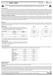
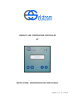
T1: vacuum line
T2: vacuum line
T3: loading line (R134a/R600a)
T4: connector tube between loading unit and coolant
cylinder support (R134a/R600a)
L1: valve for separation of R134a section and R600a
section
L1: valve for separation of R600a vacuum section and
R600a section
VAC: valve for separation of pump and vacuum section
VAC1: valve for vacuum lines T1-T2
VAC2: vacuometer valve
VAC3: valve for separation of vacuum/load section
VS: pressure gauge safety valve
V: mechanical vacuometer
M1: low-pressure pressure gauge (R600a)
M2: low-pressure pressure gauge (R134a)
R1: pressure gauge valve (R134a)
R2: pressure gauge valve (R600a)
R3: valve on coolant cylinder support
S: vacuum sensor (future applications)
I: liquid gas flow indicator
H: three-way coupling (future applications)
2/7
INTRODUCTION
Separation of the vacuum section from the loading section
During vacuum operations, any residue and pollutants present in the cooling circuit tend to accumulate in the
tubes and the circuit of the coolant loading unit. On the old type of units, the gas flows through the same
section and the same tube connected to the low-pressure section, drawing all the residue and pollutants that
have accumulated during vacuum operations into the cooling circuit.
The design of the new unit is based on the separation of the vacuum section from the loading section (by valve
VAC3). This prevents the residue and pollutants that accumulate in the lines and in the vacuum section during
pumping operations from re-entering the cooling circuit together with the cooling gas during the coolant loading
phase.
In view of the necessity of increased precision in the quantity of gas loaded, the loading cylinder for R134a has
been eliminated; in this way, the unit becomes more flexible, and is able to operate in identical conditions with
both R134a circuits and R600a circuits.
Vacuum operations in R134a and R600a circuits
The ester oil present in R134a circuits is chemically incompatible with the mineral oil used in R600a circuits.
Therefore, in order to avoid mixing the oils that accumulate in the circuit and in vacuum lines T1 and T2 during
vacuum operations on an R134a circuit with mineral oil accumulating during the same operations on an R600a
circuit, it is advisable to use two separate tubes, one for use with R134a and the other for use with R600a.
In addition, in order to avoid mixing the oils in the vacuum section, it is necessary to clean the section (using a
flow of liquid gas) using R134a. Obviously, valves L1 and L2 and VAC3 must be opened during this procedure.
Close VAC2 and VAC, open the valves of the three-way couplings or unscrew the Hansen couplings.
The sections in the loading circuit, it will be seen, never come into contact with residue, pollutants or oil.
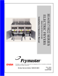
CHARACTERISTICS
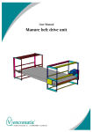
Sections of the coolant loading unit
The loading unit consists of three sections:
1. Section for vacuum operations
2. Section for loading with R600a
3. Section for loading with R134a.
The section for vacuum operations can be separated from the R600a loading section by closing valve VAC3.
The sections for loading with R600a and/or R134a can be separated from each other by closing valves L1 and
L2.
1
2
3
VAC 2
VAC 1
R1
R2
VAC 3
L2
L1
SECTION FOR VACUUM
OPERATIONS
R600a LOADING
SECTION
3/7
R134a LOADING
SECTION
Location of leaks
Separation of the various sections and the use of the various valves makes it possible to identify the part of the
loading unit where the leak occurs. The following pages contain a step-by-step description of the procedure
used to check for and identify possible leaks.
CHECKING THE LOADING UNIT FOR LEAKS
The procedure used to check the loading unit for leaks consists of an initial inspection of the levels indicated by
the pressure gauges in order to ensure that the circuit does not contain pressurized gas; the second phase
consists of a vacuometer check, which may be performed using the mechanical vacuometer fitted to the
loading unit itself or, if preferred, a digital vacuometer. Naturally, the reading provided by the digital vacuometer
will be more accurate than is possible with the mechanical version; this may therefore be considered to be a
further check.
N.B.: The Hansen or three-way couplings, too, are subject to leaks. Therefore, the checks described in this
document must all be carried out with the couplings fitted to the R134a and R600a loading lines (tubes
T4 and T3) and on the vacuum lines (tubes T1 and T2).
Visual inspection of low-pressure manometers
a) The initial situation assumes that the last operation performed using the loading unit was a coolant load
(R134a or R600a), therefore that vacuum lines T1 and T2, load line T3 and tube T4 are correctly connected
and complete with Hansen or three-way couplings, that valves L1 and L2 are closed, valve VAC2 (which
protects the vacuometer) and valve VAC (which excludes the pump) are closed.
b) First, inspect pressure gauges M1 and M2 to check that the loading sections 1 and 2 of the circuit are not
pressurized by the gas loaded previously. Then check that the pressure shown on the low-pressure
pressure gauge for the R134a or the R600a is not in excess of zero.
If the pressure gauge reading indicates a pressure that is greater than zero, i.e. that the circuit contains
residual pressurized gas, it is necessary to drain off this residual gas through the load lines T3 by loosening
the female Hansen coupling or (in the case of a three-way coupling) by opening the valve. When the lowpressure pressure gauge indicates zero, re-tighten the coupling.
c) Open valves L1, L2, VAC1, VAC3 and VAC2 in order to place the sections in communication with each
other.
d) Switch on the pump.
e) Open valve VAC, which intercepts the tube between the pump and the vacuum section.
f) After about one minute, check that the low-pressure pressure gauge indicates the minimum reading (i.e. –1
bar).
N.B. The purpose of this initial phase of the control procedure is to ensure that the circuit contains no pressure
that might damage the vacuometer. Consequently, the vacuometer must never be used during this
phase (valve VAC must always remain closed).
Check using mechanical vacuometer (with the pump in operation)
g) Open VAC2 and check that the vacuometer indicator moves to the "maximum vacuum" position (i.e. the
rightmost position, towards the end of the scale, at which the pointer stops and stabilizes with the pump in
operation).
h) If the "maximum vacuum" position is reached (i.e. if the pointer stops on zero), proceed to step i).
Otherwise, if the vacuometer pointer does not reach zero, this means that there is a relatively significant
leak or that it is necessary to change the oil (which reduces the efficiency of the pump).
In this case, all parts of the loading unit must be checked, one by one, as described in step m) in order to
identify the leak. If no leaks are found, the oil should be changed (even if it has been changed recently).
i) Wait a few minutes (about 3 to 5), then close VAC in order to exclude the pump.
l) Wait a few more minutes and check that the pointer on the vacuometer does not start to rise. If the pointer
remains stationary, then there are no leaks in the circuit, otherwise proceed from to m).
4/7
m) Localization of the leak (with the pump in operation):
VAC
VS
1) Vacuum section: with valve VAC3
closed, check for leaks:
a) in the connections between the
vacuum line (T1 and T2) and the section
of the circuit (the valves must be securely
tightened and the seal inside the tube
must be efficient).
b) in the connections between the
vacuometer and the loading unit.
c) in safety valve VS.
d) in vacuum lines T1 and T2.
e) in the Hansen or three-way couplings
(with valves closed) connected to vacuum
lines T1 and T2.
VAC2
VAC3
VAC1
T1/T2
2) T600a / R134a section: with valve VAC3 open, check for leaks:
a) in the connections between load line T3 and the loading unit.
b) in the connection between the pressure gauge and the section of the circuit.
c) In the connections between the R600a section and the two adjacent sections (vacuum and R134a).
d) in the connection between loading tube T4-cylinder support/loading section.
e) in loading line T3 (R134a/R600a) with the valve closed.
f) in the Hansen coupling connected to loading line T3.
g) in tube T4 attached to the R600a/R134a cylinder (open L1 and/or L2).
VAC3
R3
R2
L2
L1
R2
5/7
Check using digital vacuometer (with the pump in operation)
VAC
VAC1
g) Open VAC and VAC1 leaving VAC2 closed and wait until the "maximum vacuum" position is reached; these
pumps reach a maximum vacuum of 0.350 mmHg (indication on TIF vacuometers); however, the pressure
may be lower, depending on the performance of the pump.
h) If the "maximum vacuum" position is reached, proceed to step i), otherwise, there is either a major leak or
the oil requires changing. In this case, first check for the existence of a leak as described in step m); if no
leaks are found, the oil must be changed (even if it has been changed recently).
i) Wait for two minutes, then close VAC in order to exclude the pump. Record the "maximum vacuum" position
indicated by the vacuometer at the moment of closing VAC; this value indicates the maximum vacuum
reached.
l) Wait for one or two minutes: during this period, the reading indicated by the digital vacuometer will rise even
if there are no leaks, because the instrument can detect the slight increase in pressure that occurs in all
loading units. However, this increase must be gradual rather than rapid. In other words, over a period of
about two minutes, the pressure should not increase beyond 1.5 mmHg more than the "maximum vacuum"
value reached previously; i.e. the value indicated must be less than "maximum vacuum" + 1.5 mmHg. If
this is not the case, there is a leak which must be localized as described in step m) of the procedure using a
mechanical vacuometer.
Example: After about two minutes of operation of the pump, the value indicated by the vacuometer is stable
at a "maximum vacuum" of 0.350 mmHg. Close VAC to exclude the pump and wait another couple of
minutes to see how rapidly the value indicated by the digital vacuometer rises. If, after two minutes, the
value indicated is less than 0.350 ("maximum vacuum") + 1.5 (pressure increase) = 1.850 mmHg, then there
are no leaks from the loading unit.
If the procedures described in step h) or step m) do not have any effect, it is advisable to return the
loading unit to the manufacturer for repairs.
N.B. It is advisable to perform the procedure for checking the tightness of the loading unit more than once, in
order to avoid random errors.
6/7
OIL CHANGES
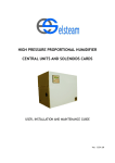
Procedure for changing the oil
1) Remove filler cap C.
2) Remove screw B to drain the used oil.
3) Replace and tighten screw B and fill with fresh oil until the level reaches the midway point of the level
indicator (A).
** DEGASSING
VALVE
C - OIL FILLER CAP
A – OILLEVEL
INDICATOR
B - DRAIN TAP
Frequency of oil changes
If the pump is used only once daily, the oil should be changed monthly.
However, it is necessary to take into consideration the conditions of the circuit in which the vacuum is created.
For example, in the case of a damaged roll-bond evaporator into which water has penetrated, the oil must be
changed after each intervention.
In addition, even if the pump is not utilized, the oil absorbs humidity and must in any case be changed.
**Degassing valve/steam vent: unscrew by between 1/4 turn and 1 turn (maximum) to degas if the
circuit contains humidity or residual gas during the final phase of draining in order to reach the
"maximum vacuum" level.
COMPONENTS INCLUDED IN THE LOADING UNIT KIT
1) Support for liquid gas cylinder (A).
2) Electronic precision balance (B).
3) Gas loading tube (C).
A
C
B
7/7