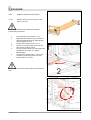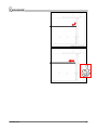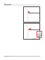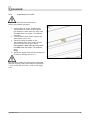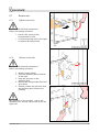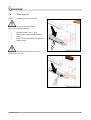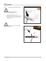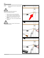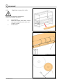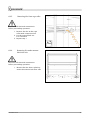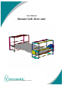
1
User Manual
Manure belt drive unit
©2005 Vencomatic bv - um-MBA/MBR-01-en/May’05
© 2005 Vencomatic ® B.V. – Nederland
All rights reserved.
The provided information can in no way be reproduced and/or published, in any form or by any
means (electronic of mechanical), without prior written permission from Vencomatic ® B.V.
The provided information is based on general data concerning the -at the time of the release
known- constructions, material characteristic and work methods, so changes are reserved.
The provided information is valid for the product in the standard type. Vencomatic ® B.V. can
therefore not be held responsible for damage resulting from a standard type deviant
specification of the product.
The provided information is made with all possible care, but Vencomatic ® B.V. cannot be held
responsible for errors or the results of errors in the information.
The by Vencomatic ® B.V. used usernames, trading names, trademarks, etc can according to
trading laws not be used.
Table of contents
Manure belt drive unit .................................................................................................................. 1
1
FOREWORD ..................................................................................................... 4
1.1
1.2
1.3
1.4
1.5
1.6
1.7
1.8
1.9
1.10
1.11
1.12
1.13
1.14
1.15
2
2.1
2.2
2.3
3
3.1
4
4.1
5
5.1
6
6.1
6.2
6.3
6.4
6.5
6.6
6.7
6.8
7
7.1
8
9
This manual................................................................................................................... 4
Manual .......................................................................................................................... 4
Document codes............................................................................................................ 4
Stickers on the machine................................................................................................. 5
Icons in this document .................................................................................................. 6
Available documentation ............................................................................................... 6
List of terms .................................................................................................................. 7
Service and technical support ........................................................................................ 7
Identification of the system ........................................................................................... 8
The machine and the environment................................................................................. 8
Discard the machine ...................................................................................................... 8
General safety instructions ............................................................................................ 9
Taken safety measures for this machine ......................................................................10
CE-marking, intended use............................................................................................10
Warranty regulations ...................................................................................................11
GENERAL DESCRIPTION................................................................................. 12
Description Manure belt drive unit...............................................................................12
Purpose / use ..............................................................................................................12
Productspecifications...................................................................................................12
TECHNICAL DATA ......................................................................................... 13
Technical data Manure belt drive unit ..........................................................................13
TRANSPORT .................................................................................................. 14
Transport safety regulations........................................................................................14
STORAGE ...................................................................................................... 15
Storage safety regulations ...........................................................................................15
OPERATION .................................................................................................. 16
Operation elements .....................................................................................................16
Emergency stop ...........................................................................................................16
Clean Manurebelt ........................................................................................................16
Manure belt .................................................................................................................17
Scraper ........................................................................................................................22
Pinch roller ..................................................................................................................23
Return unit ..................................................................................................................27
Removing dirt ..............................................................................................................28
SETTINGS ...................................................................................................... 33
Settings table...............................................................................................................33
MAINTENANCE .............................................................................................. 34
FAILURE ........................................................................................................ 36
9.1
Failure table.................................................................................................................36
10
INDEX .................................................................................................... 38
um-mbar-01-en
3
1
Foreword
1.1
This manual
This manual is made as a reference book for the machine that is mentioned on the cover of this
document. Only qualified users can use and maintain this machine in a safe way. Keep the
manual in the same place near the machine. If the manual gets lost order a new one via your
supplier.
This manual provides you with information about safety, technical specifications, operation and
maintenance. Take your time to read this document carefully before using the machine.
The machine is developed with all care and meets the CE-marking. Therefore it is not allowed to
modify the machine.
The machine is inspected thoroughly before delivery to you.
Note the registration number of the machine. You can find this number on the production label
of the machine. Make sure to have this number at hand in case you want to contact the service
department of you supplier.
Vencomatic is not responsible for damage or injury caused by not following the instructions
mentioned in this manual.
1.2
Manual
Everyone working with or near the machine should know the contents of this manual. Follow the
instructions in the manual. The management should instruct the personnel according to this
document and follow all regulations and suggestions.
Never change the order of the to do actions.
Keep this manual during the lifetime of this machine in the same place near the machine. The
manual should be at the users disposal.
1.3
Document codes
The document code consists of six parts:
•
•
•
•
•
•
Field 1: document type
Field 2: product type
Field 3: version number
Field 4: language code
Field 5: month of publication
Field 6: year of publication
um-mbar-01-en
4
1.4
Stickers on the machine
Following stickers are applied to the machine. See picture below.
um-mbar-01-en
5
1.5
Icons in this document
In the manual of this machine the following icons are used:
Careful
Procedures that can cause damage to the product, surroundings or environment.
This damage can occur if procedures are not carried out carefully.
Warning
Danger for electricity / electrical power.
Remarks, suggestions and advices.
Pull out the plug first before proceeding operation.
Consult the indicated Information source first.
Protect against water and moisture.
Watch out!
Procedure that needs extra attention.
1.6
Available documentation
The following documentation of the Manure belt drive unit is available:
•
User manual (Manure belt drive unit MBA 01-en/May -2005)
um-mbar-01-en
6
1.7
List of terms
In this manual the following terms are used:
Technician
A trained -and therefore acquainted with the applied
technique- expert familiar with the possible dangers of
the machine. Technicians have a minimum age of 19
years. They have a solid knowledge of transport
techniques. Technicians are authorized to transport,
install, place in operation and repair the machine.
Authorized user
See 'User'. The 'authorized user' is also authorized to
install and commission the machine.
User
The customer using the machine according to the
purpose detailed in the concerning user manual. The user
is responsible for the operation and the in the user
manual described periodic adjustment, cleaning and
maintenance of the machine.
Transportbandsysteem
Aanduiding voor elke mogelijke variant van de machine.
Component
Aanduiding voor ieder los te schakelen deel van de
machine.
Flock
Indication for the economic life cycle of the chickens.
1.8
Service and technical support
When an item is not discussed in this manual contact your local Vencomatic dealer for
information about specific procedures.
um-mbar-01-en
7
1.9
Identification of the system
The production label is placed on the drive unit. See picture below.
The number on the production label represents the order number.
1.10
The machine and the environment
1.10.1
Packaging material
The packaging material mainly consists of:
•
•
•
(corrugated) cardboard
(untreated) wood
plastic packaging material
Inform the customer to inquire about the possibilities for recycling and environmentally friendly
disposal / re-use of the packaging materials.
1.11
Discard the machine
Discarded machines should be disposed of in an environmentally friendly way according to the
local regulations. The used materials can be subdivided roughly in:
•
•
•
•
•
•
plastic (egg carrier on chain, dirt tray, various plugs)
untreated metal (shafts)
coated metal (motor and bearing block)
galvanized metal (sheet metal, fastening materials, legs)
aluminum (side profiles of section)
oil and grease (in motor, bearing block and oil lubrication system)
If an electrical control panel is supplied:
The printed circuit board(s) and their components in the control panel are electrical waste.
um-mbar-01-en
8
1.12
General safety instructions
Vencomatic B.V. will not accept any claim for damage or injury caused by not following the safety
regulations and safety instructions, or carelessness during:
•
•
•
•
•
•
transport,
installation,
commissioning,
operation,
maintenance,
troubleshooting and repair,
of the machine and possible accessories. Depending on specific working circumstances or
additional accessories, additional safety regulation can be needed. If during previous the
aforementioned activities a potential danger occurs, please contact Vencomatic B.V. immediately.
1.12.1
•
•
•
•
Installation manual / user manual
Every technician has to know the contents of the installation manual. The technician must
follow the instructions in the installation manual conscientiously.
Every (authorized) user has to know the contents of the user manual and follow the
instructions in the user manual conscientiously.
Never change the order of the “to do” actions.
Store this manual carefully.
1.12.2
Stickers and instructions on the machine
Stickers, symbols and instructions are an integral part of this machine’s safety precautions. It is
therefore not allowed to cover them up and / or remove them. They have to be present and
legible during the whole life cycle of the system.
•
Replace or repair illegible stickers, symbols and instructions immediately.
1.12.3
Technician
Transport, installation and commissioning of the machine is allowed for authorized and trained
technicians only. (See 'Terms and Definitions'.) While carrying out their work they are always fully
responsible for compliance of local safety regulations and guidelines. Temporary personnel and
persons in training are allowed to work with the machine under supervision of an authorized
technician only.
1.12.4
Authorized users
An authorized user is the customer using the machine. This use is in accordance with the
purpose of the user guide. The user is responsible for the operation of the machine. The user
takes care of periodic adjustment, cleaning and maintenance of the machine. These items are
written down in the user manual.
The ‘authorized user’ is also authorized for installation and commissioning of the machine.
um-mbar-01-en
9
1.12.5
Technical specifications
The technical specifications cannot be changed.
1.12.6
Modifications
Modification of (or parts of) the machine is not allowed. Use original (spare)parts advised by the
manufacturer only.
1.13
Taken safety measures for this machine
The following safety measure protections are present:
•
•
•
Guard for transfer brush on drive unit.
Warning stickers, see ‘Stickers on the machine’.
Electrical protection, see ‘Manual Electrical Control Panel’.
1.14
CE-marking, intended use
1.14.1
Machinery directive
The machine is constructed according to the machinery directive. Therefore the machine is CEmarked.
CE-marking means that the machine at the time of delivery met the CE-requirements applied to
the machine at that moment. The responsibility for CE-conformity for the machine expires
entirely or partly and changes to the buyer if the following conditions are not observed:
The CE-marking is applied only to the machine.
•
•
•
The machine can only be used in observance with the contents of this user manual.
The machine can only be used within the range of the products specifications.
The original state of the machine cannot be changed without written authorization of
Vencomatic B.V.
1.14.2
Purpose Manure belt drive unit
The Manure belt drive unit is a machine ton drive the manure belt.
Every other or further use is not regarded conform the purpose. Vencomatic is not responsible
for damage or injury because of this. The machine is constructed according to the valid
requirements and standards. Use the machine only in technical perfect state, conform previous
mentioned purpose.
1.14.3
Use according to purpose
The "Use according to purpose" as recorded in the EN 292-1 is the use where the technical
product according to its specifications -including its possibilities according to the sales brochureis capable of. When in doubt this is the use that seems obvious resulting from construction, type
and function of the product. “Use according to purpose” also includes following the instructions
in the user guide.
um-mbar-01-en
10
1.15
Warranty regulations
The warranty regulations applied to the machine are recorded in the terms of delivery and
payment of Vencomatic BV, registered at the chamber of commerce in Eindhoven with number
873/94.
The warranty has a validity of 12 months.
The warranty expires if:
•
•
•
•
•
•
The warranty validity is past 12 months.
Not authorized changes and / or modifications are applied to the machine.
Parts and consumer goods that are not supplied by the manufacturer are applied.
The maintenance is not carried out according to the indications in the manual.
The machine in not set up conform the guideline indicated by Vencomatic.
The machine is installed incompetently.
um-mbar-01-en
11
2
General description
2.1
Description Manure belt drive unit
The Manure belt drive unit is not made up of modular components. This means that different
positions are not possible.
2.2
Purpose / use
The Manure belt drive unit is designed to drive a manure belt.
2.3
Productspecifications
Only manure belts driven with this machine.
um-mbar-01-en
12
3
Technical data
3.1
Technical data Manure belt drive unit
3.1.1
General Manure belt drive unit
Description
General
Material
Sendzimir, RVS, PUR, PA, SBR
3.1.2
Dimensions Manure belt drive unit
3.1.3
Electrical installation Manure belt drive unit
Description
Power (Watt)
Mains voltage
(V)
Oil V (liter) **
Motor SK01-71 L/4 0.37KW n=27
0.37
3x230 / 3x400
0.25
Motor SK25-80 L/4 0.75KW n=25
0.75
3x230 / 3x400
0.7
Motor SK305-90 L/4 1.1KW n=22
1.1
3x230 / 3x400
1.4
* motor type to be installed after consultation with dealer
** Oil: 100% synthetic, class ISO VG 220
Electrical data is subject to changes.
um-mbar-01-en
13
4
Transport
4.1
Transport safety regulations
See also 'General safetyprescription and -instructions '.
um-mbar-01-en
14
5
Storage
5.1
Storage safety regulations
•
•
•
•
•
See also 'General safety instructions'.
Respect the surrounding conditions. Never store the system in a room where the temperature
can get under +10 °C. Lower temperatures can damage sensitive parts.
Store the system in a dry and dust free room.
Place the system on a level floor.
Never place heavy products on top of lighter products.
um-mbar-01-en
15
6
Operation
6.1
Operation elements
The machine is operated from the central
control panel.
6.2
Emergency stop
On the electrical control panel there is
an emergency stop.
See also ‘Manual Electrical Control Panel’
for further information.
6.3
Clean Manurebelt
1. Tighten scraper
2. Switch on manure belt drive unit on the
central control panel
3. Let the manure belt make one rotation
4. Switch off manure belt drive unit on the
central control panel
5. Loosen scraper
Never run the manure belt unattended
um-mbar-01-en
16
6.4
Manure belt
6.4.1
check manure belt position
Disconect all electrical connections before
proceeding operation.
1. Check if the manure belt does not
touches the sides. At the manure belt
drive side as well as the return side
•
•
Position manure belt in figure
271500.06.0.02.007.01.0-xx is
incorrect
Position manure belt in figure
271500.06.0.02.008.01.0-xx is
correct
um-mbar-01-en
17
um-mbar-01-en
18
6.4.2
Regulate manure belt position
6.4.2.1
Manure belt position to much on the
right or the left
Disconect all electrical connections before
proceeding operation.
1.
2.
3.
4.
5.
6.
Loosen bolts on position 1 en 2
Regulate the manure belt position in
the desired direction by twisting the
adjustingbolt ¼ turn
Fasten bolts on position 1 en 2
Switch on manure belt drive unit on
the central control panel
Let the manure belt run and judge the
regulation (see also: 6.3 Clean
Manurebelt)
If necessary repeat step 1 up to and
including 5 till the position of the
manure belt is correct
Never carry out these instructions on the motor
side.
um-mbar-01-en
19
um-mbar-01-en
20
um-mbar-01-en
21
6.5
Scraper
6.5.1
Tighten scraper
Disconect all electrical connections before
proceeding operation.
1. Hook the lever by lifting and moving
sideways
2. Repeat step 1 for the left side of the
Manure belt drive unit
6.5.2
Release scraper
Disconect all electrical connections before
proceeding operation.
1. Release the lever by lifting and moving
sideways
2. Repeat step 1 for the left side of the
Manure belt drive unit
um-mbar-01-en
22
6.6
Pinch roller
6.6.1
Tighten pinch roller
Disconnect all electrical connections
before proceeding operation.
1. Turn the adjusting bolt to the right
to tighten the pinch roller
The position of the pinch roller should be
equal for left-hand side as well as for the
right-hand side, this to prevent the deviation
of the manure belt
6.6.2
Loosen pinch roller
Disconnect all electrical connections
before proceeding operation.
1. Turn the adjusting bolt to the left
to loosen the pinch roller
The position of the pinch roller should be
equal for left-hand side as well as for the
right-hand side, this to prevent the deviation
of the manure belt
um-mbar-01-en
23
6.6.3
Check pinch roller position
Disconnect all electrical connections
before proceeding operation.
1. Check the pinch roller position in
the belt adjusting unit. This
should be in the middle of the range.
Pay attention: this check should be done when
the system is in standstill mode.
•
Position of the pinch roller in
figure 271500.06.0.02.023.00.0-xx
is correct
•
Position of the pinch roller in
figure 271500.06.0.02.024.00.0-xx
is incorrect
•
Position of the pinch roller in
figure 271500.06.0.02.025.00.0-xx
is incorrect
um-mbar-01-en
24
um-mbar-01-en
25
6.6.4
Adjusting Pinch roller
Disconnect all electrical connections
before proceeding operation.
1. Loosen the bolt in the middle of the
tensionbeam so that it is tensionfree
Pay attention: these bolts are only used
fore MBA from 2.0 meter +35 sections
and lager
2. Loosen pinch roller till the springs are
tensionfree (see 6.6.2)
3. Fasten the bolt in middle of the
tensionbeam till it gets under tension.
Than turn the bolt 3 more times.
Pay attention: these bolts are only used
fore MBA from 2.0 meter +35 sections
and
larger
4. Fasten the pinch roller till the springs are
pushed in halfway (see 6.6.1)
Pay attention: adjust the (red) spring right and
left side equally. Take smale steps for example:
1 turn on the left and than 1 turn on the right
side.
um-mbar-01-en
26
6.7
Return unit
6.7.1
Tighten return unit
Disconect all electrical connections
before proceeding operation.
1. Check if the spring of the
fixing handle is fixed
1. Turn the adjusting bolt to the right
to tighten the manure belt
6.7.2
Release return unit
Disconect all electrical connections
before proceeding operation.
1. Release fixing handle
2. Turn the adjusting bolt a little bit
to the right
3. Keep the pressure on the
adjusting bolt
4. Remove the fixing handle from the
gear wheel
5. Gentlely release the pressure from
the adjusting bolt (release fork
spanner)
Pay attention!. Carry out Step 1 up to and
including 5 for the left-side as well as for the
right-side
um-mbar-01-en
27
6.8
Removing dirt
6.8.1
Removing dirt from scraper
Disconect all electrical connections
before proceeding operation.
1.
2.
3.
Release scraper (see: 1.5.2)
Remove dirt with the added filling
knife
Brush off the remaining dirt with the
added brush
After cleaning always check if the electrical
components are dry
um-mbar-01-en
28
6.8.2
Removing dirt from pinch roller
Disconect all electrical connections
before proceeding operation.
1. Release scraper (see: 1.5.2)
2. Remove dirt with the added filling knife
3. Brush off the remaining dirt with the
added brush
After cleaning always check if the electrical
components are dry
um-mbar-01-en
29
6.8.3
Removing dirt from the manurebeltsupport
Disconect all electrical connections
before proceeding operation.
1. Remove dirt from the manurebeltsupport with the added filling knife.
2. Brush off the remaining dirt from the
manurebelt-support with the added
brush.
3. Repeat step 1 and 2 for all manurebeltsupports
After cleaning always check if the electrical
Components are dry
um-mbar-01-en
30
6.8.4
Regulating scraper pinch roller
Disconect all electrical connections
before proceeding operation.
1.
2.
3.
Loosen bolts
Move the scraper pinch roller so that
the space between pinch roller and
scraper is 2mm
Fasten bolts
um-mbar-01-en
31
6.8.5
Removing dirt from cage roller
Disconect all electrical connections
before proceeding operation.
1. Remove the dirt in the cage
roller with compressed air
2. Let the manure belt run
For a moment
3. Repeat step 1
6.8.6
Removing dirt under manure
belt drive unit
Disconect all electrical connections
before proceeding operation.
1. Remove the dirt that is piled up
under the manure belt drive unit
um-mbar-01-en
32
7
Settings
7.1
Settings table
Disconect all electrical connections before proceeding operation.
Frequency
What to do
Settings when putting into use
Check tension manure belt
Settings during ‘in operation’ situation
Check manure belt position
Check if the manure belt slips
Check scraper pinch roller
Check if the scraper is tightened
Adjust scraper onto the manure belt
Setting after one flock
Check if the bearings run smooth
Check tension manure belt
Check manure belt position
Check if the manure belt slips
Check scraper pinch roller
Check if the scraper is tightened
Release manure belt
Settings before starting a new flock
See “ Settings when putting into use ”
um-mbar-01-en
33
8
Maintenance
Disconect all electrical connections before proceeding operation.
Always check if the electrical connections are dry after cleaning.
Frequency
What tot do
Where on the machine
After installation
Check tension manure belt
MBR* hexagon in tube
Check manure belt position
Check if the manure belt slips
Adjusting bolts on MBA,
chainbolts on MBR
Adjusting bolts under MBA
Check scraper pinch roller
Underside MBA
Release scraper
Scraper at the front of the
MBA
Scraper at the front of the
MBA
Maintenance before
putting into use
Tighten scraper
’in use’ Situation:
Every 2 days
(manurebeltsystems
shorter then 80 meter
without manuredrying)
Clean manure belt
Total system
Every 3 days
(manurebeltsystems
shorter then 80 meter
with manuredrying)
Clean manure belt
Total system
Every day
Clean manure belt
Total system
Clean manure belt
Total system
(manurebeltsystems
longer than 80 meter
without manuredrying)
Every 2 days
(manurebeltsystems
longer than 80 meter
with manuredrying)
*MBA = Manure belt drive unit
**BSU = Manurebelt return unit
um-mbar-01-en
34
Maintenance after ‘being
in opperation’ Situation
Maintenance after after
one flock
Release scraper
MBA*
Remove dirt from scraper
MBA
Remove dirt under manure belt drive
unit
Remove dirt from cage roller
MBR
Remove dirt in MBA
MBA
Regulate manure belt position (if
necessary)
Regulate manure belt position (if
necessary)
Remove dirt from manurebelt-support
Adjusting bolts on MBA
Release return unit
MBR
Yearly maintenance/
Clean MBA and MBR
maintenance after after 1
flock
MBR
MBR
Housing
MBA and MBR
Clean motor reductor (cooling fins and
paddle wheel)
Check motor reductors
MBA
Check oillevel motor reductor
MBA
Check electrical fuctions
MBA
Check electrical connenctions
Dry terminal board
MBA
MBA
Tighten chain
MBA
Lubricate chain
MBA
Lubricate adjusting bolts
MBA
Check on rust/ corrosion
MBA and MBR
MBA
Check all parts that are subject to wear and MBA and MBR
tear: chain wheels, chains, plastics, gear
wheels, thrust block (only used in 2,3 m
drive units), pinch roller, bearings, adjusting
bolts, springs, scrapers, chain tightener.
Rust/corrosion prevention
MBA and MBR
*MBA = Manure belt drive unit
**BSU = Manurebelt return unit
um-mbar-01-en
35
9
Failure
9.1
Failure table
Disconect all electrical connections before proceeding operation.
Failure
Cause
Solution
Manure belt does not get
clean
Scraper is dirty or is not in
contact with the manure belt
Clean scraper and adjust the
scraper onto the manure belt
Drive roller is dirty
Pinch roller is dirty
Pinch roller wrongly adjusted
Clean drive roller
Clean pinch roller
Clean entire system and
subsequently tighten pinch
roller
Replace pinch roller
Tighten manurebelt near MBR*
Pinch roller worn
Manure belt return wrongly
adjusted
To much manure on the manure
belt
Water on the manure belt
Motor not running
Motor stalls
To much manure on the manure
belt
Bad electrical contact
Motor broken
To much manure on the manure
belt
Bad electrical contact
Motor makes noise
Chain tension fault
No chain lubrication
No or not enough lubricant in
motor reductor
Dent in the lid of the motorfan
Manure belt position in
the system is wrong
Manure belt slips
um-mbar-01-en
Remove manure by hand and
increase the frequency of
cleaning the manure belt
Remove water by hand and
increase the frequency of
cleaning the manure belt
Remove manure by hand and
increase the frequency of
cleaning the manure belt
Check all electrical connections
Replace motor
Remove manure by hand and
increase the frequency of
cleaning the manure belt
Check all electrical connections
Tighten Drive chain
If necessary replace chain and
chain wheels
Lubricate chain with lubrication
Refill oil according to table
Pinch roller not equaly adjusted
Remove dents from the lid of
the motorfan
rearrange the perches, feeding
system and drinking line in the
system
Regulate manure belt position
Tension on pinch roller Manure
belt return unit incorrect
Readjust (red) tension springs
Manurebelt return unit
Manure unequaly spreaded
36
Driveroller slips
Pinch roller wrongly tightened
Tighten pinch roller equally
Water
Remove water by hand
Look up the problem and fix the
leakage
*MBA = Manure belt drive unit
**BSU = Manurebelt return unit
um-mbar-01-en
37
10
Index
A
Authorized user............................................................................................................................7
C
Chicken eggs ..............................................................................................................................12
Component...................................................................................................................................7
D
Discard .........................................................................................................................................8
Document codes...........................................................................................................................4
E
Einstellungen ..............................................................................................................................33
Einstellungstabelle......................................................................................................................33
Emergency stop ..........................................................................................................................16
F
Failure ........................................................................................................................................36
Flock.............................................................................................................................................7
G
Guarantee regulations ................................................................................................................11
I
Icons.............................................................................................................................................6
Identification of the system ..........................................................................................................8
L
Lagerung ....................................................................................................................................15
List of terms .................................................................................................................................7
M
Machine
discard ......................................................................................................................................8
Machinery directive.....................................................................................................................10
Maintenance ...............................................................................................................................34
Modifications ..............................................................................................................................10
O
Operation elements ....................................................................................................................16
P
Packaging material .......................................................................................................................8
Production label............................................................................................................................8
Productspecifications..................................................................................................................12
S
Safety instructions ........................................................................................................................9
Safety measures..........................................................................................................................10
Service ..........................................................................................................................................7
Settings ......................................................................................................................................33
Stickers.........................................................................................................................................9
Storage safety regulations ..........................................................................................................15
T
Technical specifications ..............................................................................................................10
Technical support .........................................................................................................................7
Technician
responsibilities..........................................................................................................................9
Technician ....................................................................................................................................7
Technische Daten .......................................................................................................................13
Technische Daten Antriebeinheit ................................................................................................13
Transportbandsysteem .................................................................................................................7
Turky eggs .................................................................................................................................12
U
Unterhaltung ..............................................................................................................................34
User..............................................................................................................................................7
um-mbar-01-en
38
responsibilities..........................................................................................................................9
V
Vencobelt
Funktion..................................................................................................................................10
um-mbar-01-en
39