1
ENG
CLUTCH
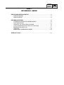
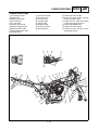
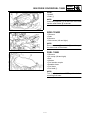
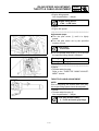
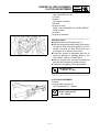
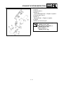
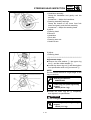
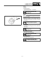
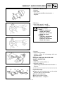
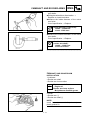
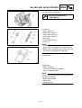
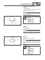
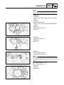
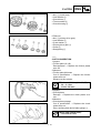
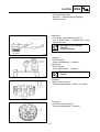
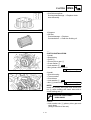
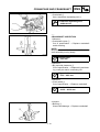
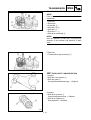
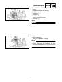
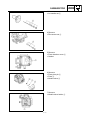
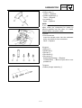
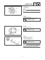
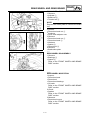
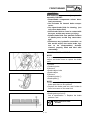
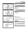
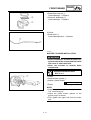
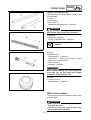
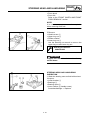
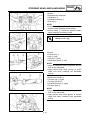
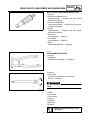
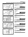
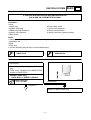
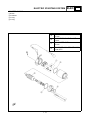
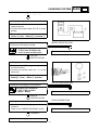
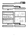
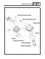
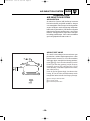
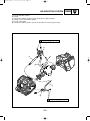
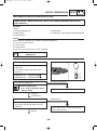
4.Install:
● Friction plate (#1) 1 (3 pcs)
● Clutch plate 2 (3 pcs)
● Cushion spring 3
● Friction plate (#2) 4
● Clutch plate 5 (2 pcs)
● Friction plate (#1) 6 (2 pcs)
● Push rod (#2) 7
● Ball 8
● Push rod (#1) 9
● Push plate 0
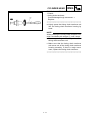
NOTE:
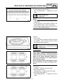
Install the clutch plates and friction plates alternately on the clutch boss, starting with a friction plate and ending with a friction plate.
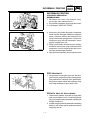
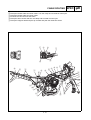
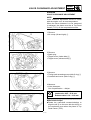
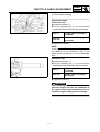
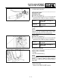
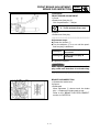
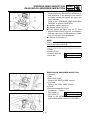
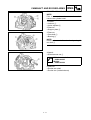
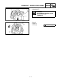
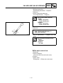
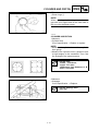
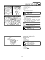
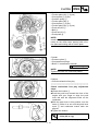
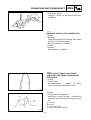
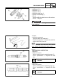
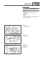
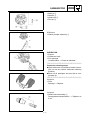
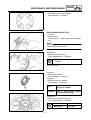
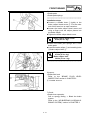
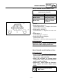
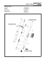
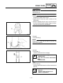
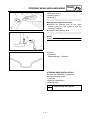
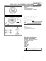
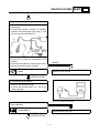
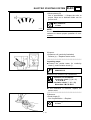
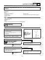
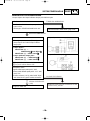
5.Install:
● Pressure plate 1
● Compression springs
● Bolts 2 (compression springs)
T.
R.
6 Nm (0.6 m • kg)
NOTE:
Tighten the bolts in a crisscross pattern.
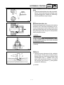
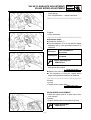
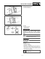
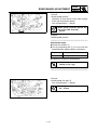
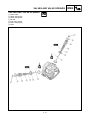
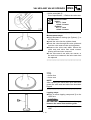
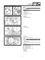
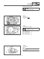
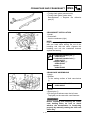
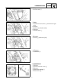
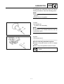
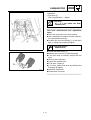
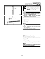
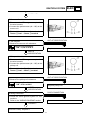
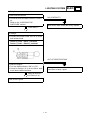
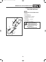
6.Adjust:
● Clutch mechanism free play
***********************************************
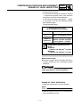
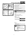
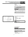
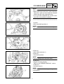
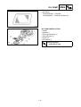
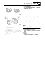
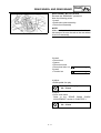
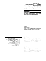
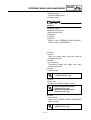
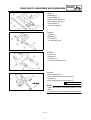
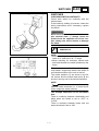
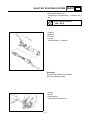
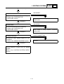
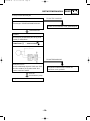
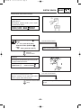
Clutch mechanism free play adjustment
steps:
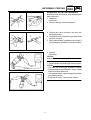
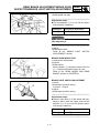
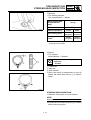
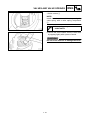
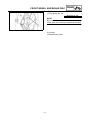
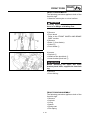
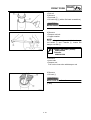
● Loosen the locknut 1
● Push the push lever toward the front of the
engine with your finger to align the push
lever tab with the alignment mark on the
crankcase.
● With the push lever in this position, turn the
screw 2 either in or out until the push lever
mark 3 and crankcase match mark are
aligned.
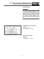
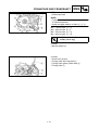
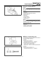
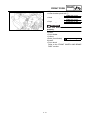
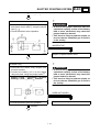
● Tighten the locknut.
T.
R.
Locknut:
8 Nm (0.8 m • kg)
***********************************************
4 - 48