1
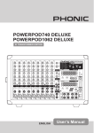
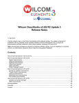
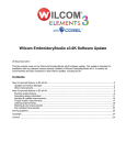
Service manual
13.
Troubleshooting
13.1 Indoor Unit Error Display
Display
LED STATUS
E0
EEPROM error
E1
Indoor / outdoor units communication protection
E2
Zero-crossing examination error
E3
Fan speed beyond control
E5
Open or short circuit of outdoor temperature sensor
E6
Room temperature or evaporator temperature sensor open or short circuit of
P0
Module protection
P1
Over voltage or too low voltage protection
P2
Compressor top protection against temperature
P3
Outdoor low temp. protection
P4
Inverter compressor drive error
Note: E4:
Reserved function
13.1.1
Display
LED STATUS
E0
EEPROM parameter error
Circuit or software error on indoor control board
Replace the control board of indoor
13.1.2 circuit or software error on indoor cortrol board
32
Display
LED STATUS
E1
Indoor / outdoor units communication protection
Service manual
Disconnect the power supply, after 1 minutes, connect the power supply , turn on the
unit using remote controller, does the unit work normally ?
NO
Is the connection on outdoor control board and
between indoor and outdoor unit good? Does the Lǃ
Does the led on outdoor control board bright?
N connect good? Does the S wire connect reliably?
YES
YES
NO
Is the voltage on terminal CZ1 and CZ2 of the outdoor main PCB is 5V?
No
Is the voltage between P and
Replace the module board.(The
Yes
power supply of PCB is supplied
N on inverter module 380V?
by the module board.)
No
NO
Replace the outdoor power
supply board.
Replace the outdoor main
PCB
13.1.3
Display
E2
LED STATUS
Zero-crossing examination error
Is power supply right?
Yes
Is connector connection good?
Yes
Indoor PCB is defective
Replace the indoor control board.
13.1.4
Display
E3
33
LED STATUS
Fan speed beyond control
Service manual
Is connector connection good?
No
Yes
Is voltage being applied to the fan motor?
(rang 90v-160v between mid pin and N on CN1
Repair the connector.
No
Yes
Indoor fan motor is defective
Indoor PCB is defective
Replace indoor fan motor.
Replace indoor main PCB.
13.1.5
Display
E5
LED STATUS
Open or short circuit of outdoor temperature sensor
Is connection to connector good?
Yes
No
Replace the sensor
Repair connector
If display E5 all the same, replace indoor main PCB.
13.1.6
Display
LED STATUS
E6
Room temperature or evaporator temperature sensor open or short circuit
Is connection to connector good?
yes
No
Replace the sensor
Repair connector
If display E6 all the same, replace outdoor main PCB.
13.1.7
34
Display
LED STATUS
P0
Module protection
Service manual
Is connection to connector good?
No
Yes
Repair connector
Is the wires to compressor right?
Yes
Check the voltage between P and N on inverter
No
module. Is it about 380V?
Test the outdoor power supply board again.
Yes
Check the inverter module, If some component
Yes
cracked or damaged?
No
Inverter module damaged, replace it.
Is it breakdown between P-N,P-U,P-V;N-W,N-U,N-V
No
At inverter module
No
Check compressor
Yes
Inverter module is defective
13.1.8
Display
P1
LED STATUS
Over voltage or too low voltage protection
Is the power supply right?
Yes
Check the outdoor power board
Replace outdoor main PCB.
13.1.9
Display
P2
Off: 115ώC;
35
On: 100ώC
LED STATUS
Compressor top protection against temperature
Service manual
Does compressor operate?
No
Yes
Is the connection good?
No
Is refrigerant circulation volume normal?
Yes
No
Connect and test again.
Is protector normal?
Gas charging
No
Yes
Replace protector
Is abnormality the same after gas charging
No
Check the outdoor main PCB
Check refrigerant system (such as clogging of
ill
t )
Replace the outdoor main PCB.
13.1.10
Display
P3
LED STATUS
Outdoor low temp. protection
This is optional, factory standard unit has not this function.
Unit stops when outdoor temp. is low than -15°C and lasting time more than 60 minutes, and unit
runs again when outdoor temp. more than -12°C.
Is the outdoor temp. low than -15°C?
No
Is the outdoor temp sensor right according to the table in clause 12
Yes
Replace the outdoor main board
13.1.11
Display
LED STATUS
P4
Inverter compressor error
Are the U,V,W connected to compressor and inverter module right?
36And is the compressor feed back wires(CN514˅connected to PCB good.˛
No
Service manual
Yes
Reconnecting
Replace outdoor main PCB
If the problem can not be solved, replace inverter module
If the problem comes to again, check wingding resistance of inverter compressor, is it 0.64 ohm?
No
Replace inverter compressor
13.2 Diagnostic chart
After energizing, no indicator is lighted and the air conditioner can’t be operated.
37
Service manual
38
Service manual
13.3 Resetting phenomenon often occurs during operation
(That is automatically entering to the status when power is on.)
The reason is that the instantaneous voltage of main chip is less than 4.5V. Check according to the
following procedure:
13.4 Operation lamp flashes and Timer lamp off
Is connector connection good?
No
Repair the connector.
Is voltage being applied to the fan motor?
Yes
No
Indoor PCB is defective.
Fan motor is defective
13.5 Operation lamp flashes and Timer lamp on
39
Service manual
13.6 Operation lamp off and Timer lamp flashes
13.7 Operation lamp on and Timer lamp flashes
EEROM error, indoor PCB is defective.
13.8 Operation lamp flashes, Timer lamp flashes
This is alarm signal when the main chip can’t detect over-zero signal. When such failure occurs, the
main control board must have fault.
40
Service manual
14
Characteristic of temperature sensor
Temp.ć
-10
-9
-8
-7
-6
-5
-4
-3
-2
-1
0
1
2
3
4
5
6
7
8
9
10
11
12
13
14
15
16
41
Resistance Kȍ
62.2756
58.7079
56.3694
52.2438
49.3161
46.5725
44
41.5878
39.8239
37.1988
35.2024
33.3269
31.5635
29.9058
28.3459
26.8778
25.4954
24.1932
22.5662
21.8094
20.7184
19.6891
18.7177
17.8005
16.9341
16.1156
15.3418
Temp.ć
17
18
19
20
21
22
23
24
25
26
27
28
29
30
31
32
33
34
35
36
37
38
39
40
41
42
43
Resistance Kȍ
14.6181
13.918
13.2631
12.6431
12.0561
11.5
10.9731
10.4736
10
9.5507
9.1245
8.7198
8.3357
7.9708
7.6241
7.2946
6.9814
6.6835
6.4002
6.1306
5.8736
5.6296
5.3969
5.1752
4.9639
4.7625
4.5705
Temp.ć
44
45
46
47
48
49
50
51
52
53
54
55
56
57
58
59
60
61
62
63
64
65
66
67
68
69
70
Resistance Kȍ
4.3874
4.2126
4.0459
3.8867
3.7348
3.5896
3.451
3.3185
3.1918
3.0707
2.959
2.8442
2.7382
2.6368
2.5397
2.4468
2.3577
2.2725
2.1907
2.1124
2.0373
1.9653
1.8963
1.830
1.7665
1.7055
1.6469