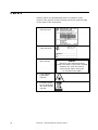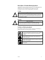
1
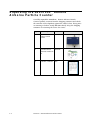
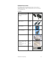
Remote Particle Counters
AEROTRAK™ Remote
Airborne Particle Counters
Models 7201/7301/7501/7310/7510
Operation Manual
P/N 6002276, Revision C
October 2010
AEROTRAK™ Remote
Airborne Particle Counters
Models 7201/7301/7501/7310/7510
Operation Manual
P/N 6002276, Revision C
October 2010
SHIP TO/MAIL TO:
TSI Incorporated
500 Cardigan Road
Shoreview, MN 55126-3996
USA
U.S.
Technical Support:
(800) 874-2811/(651) 490-2811
Fax:
(651) 490-3824
E-mail address:
[email protected]
Website:
http://www.tsi.com
INTERNATIONAL
Technical Support:
(001 651) 490-2811
Fax:
(001 651) 490-3824
Manual History
The following is a manual history of the AEROTRAK™ Remote
Airborne Particle Counters, Models 7201/7301/7501/7310/7510
Operation and Service Manual (P/N 6002276).
ii
Revision
Date
A
B
C
February 2009
February 2010
October 2010
Warranty
Part Number
Copyright
Address
E-mail Address
Limitation of Warranty
and Liability
(effective July 2000)
6002276/ Revision C / October 2010
©TSI Incorporated / 2009-2010 / All rights reserved.
TSI Incorporated / 500 Cardigan Road / Shoreview, MN 55126 / USA
[email protected]
Seller warrants the goods sold hereunder, under normal use and service as
described in the operator's manual, shall be free from defects in workmanship and
material for (24) months, or the length of time specified in the operator's manual,
from the date of shipment to the customer. This warranty period is inclusive of any
statutory warranty. This limited warranty is subject to the following exclusions:
a.
Hot-wire or hot-film sensors used with research anemometers, and certain
other components when indicated in specifications, are warranted for 90 days
from the date of shipment.
b.
Parts repaired or replaced as a result of repair services are warranted to be
free from defects in workmanship and material, under normal use, for 90 days
from the date of shipment.
c.
Seller does not provide any warranty on finished goods manufactured by
others or on any fuses, batteries or other consumable materials. Only the
original manufacturer's warranty applies.
d.
Unless specifically authorized in a separate writing by Seller, Seller makes no
warranty with respect to, and shall have no liability in connection with, goods
which are incorporated into other products or equipment, or which are
modified by any person other than Seller.
The foregoing is IN LIEU OF all other warranties and is subject to the
LIMITATIONS stated herein. NO OTHER EXPRESS OR IMPLIED WARRANTY OF
FITNESS FOR PARTICULAR PURPOSE OR MERCHANTABILITY IS MADE.
TO THE EXTENT PERMITTED BY LAW, THE EXCLUSIVE REMEDY OF THE USER
OR BUYER, AND THE LIMIT OF SELLER'S LIABILITY FOR ANY AND ALL LOSSES,
INJURIES, OR DAMAGES CONCERNING THE GOODS (INCLUDING CLAIMS
BASED ON CONTRACT, NEGLIGENCE, TORT, STRICT LIABILITY OR OTHERWISE)
SHALL BE THE RETURN OF GOODS TO SELLER AND THE REFUND OF THE
PURCHASE PRICE, OR, AT THE OPTION OF SELLER, THE REPAIR OR
REPLACEMENT OF THE GOODS. IN NO EVENT SHALL SELLER BE LIABLE FOR
ANY SPECIAL, CONSEQUENTIAL OR INCIDENTAL DAMAGES. SELLER SHALL
NOT BE RESPONSIBLE FOR INSTALLATION, DISMANTLING OR REINSTALLATION
COSTS OR CHARGES. No Action, regardless of form, may be brought against
Seller more than 12 months after a cause of action has accrued. The goods
returned under warranty to Seller's factory shall be at Buyer's risk of loss, and will
be returned, if at all, at Seller's risk of loss.
Buyer and all users are deemed to have accepted this LIMITATION OF WARRANTY
AND LIABILITY, which contains the complete and exclusive limited warranty of
Seller. This LIMITATION OF WARRANTY AND LIABILITY may not be amended,
modified or its terms waived, except by writing signed by an Officer of Seller.
Service Policy
Knowing that inoperative or defective instruments are as detrimental to TSI as they
are to our customers, our service policy is designed to give prompt attention to any
problems. If any malfunction is discovered, please contact your nearest sales office
or representative, or call TSI’s Customer Service department at 1-800-874-2811
(USA) or +001 (651) 490-2811 (International).
iii
Trademarks
AEROTRAK is a trademark of TSI Incorporated. TSI and the TSI logo are trademarks of
TSI Incorporated. Teflon is a registered trademark of DuPont. Modbus is a registered
trademark of Modicon, Incorporated. Windows and Internet Explorer are registered
trademarks of Microsoft Corporation.
iv
AEROTRAK™ Remote Airborne Particle Counters
Contents
Manual History ......................................................................................... ii
Warranty .................................................................................................. iii
Safety ...................................................................................................... vii
Laser Safety ...................................................................................... vii
Labels................................................................................................ viii
Description of Caution/Warning Symbols ....................................... ix
Caution ........................................................................................ ix
Warning ....................................................................................... ix
Caution or Warning Symbols .......................................................... ix
Getting Help ........................................................................................ x
CHAPTER 1 Introduction and Unpacking .......................................... 1-1
Unpacking the AEROTRAK™ Remote Airborne Particle Counter .....1-2
Optional Accessories .................................................................... 1-3
All Models .................................................................................. 1-3
2.83 L/min, 0.1 cfm Models (7201-xx, 7301-xx, 7501-xx) .........1-4
28.3 L/min, 1.0 cfm Models (7310-xx, 7510-xx) ........................1-5
CHAPTER 2 Getting Started ................................................................ 2-1
Indicator LEDs ................................................................................. 2-1
Electrical Connections ..................................................................... 2-2
Device Connections...................................................................... 2-2
12 VDC Connector .................................................................... 2-2
Ethernet Connector ................................................................... 2-2
Alarm, Temp/RH Connector ...................................................... 2-2
RS-232/485 Connector ............................................................. 2-3
Tubing Connections ......................................................................... 2-3
Vacuum Connector ....................................................................... 2-3
Inlet ............................................................................................... 2-4
Installation ........................................................................................ 2-4
Determine the Installation Location .............................................. 2-4
Mounting the Remote Airborne Particle Counter .........................2-5
Supplying Power to the Remote Airborne Particle Counter .........2-6
Using Power-Over-Ethernet (POE) ........................................... 2-6
Using DC Power ........................................................................ 2-7
Connecting the Remote Airborne Particle Counter to a
Computer ................................................................................... 2-8
Modbus® TCP over Ethernet ..................................................... 2-8
Ethernet Web Browser .............................................................. 2-8
Modbus® RTU over RS-485 Serial ............................................ 2-8
v
Tubing Installation........................................................................ 2-9
Connecting Vacuum Tubing ..................................................... 2-9
Connecting Sample Tubing ...................................................... 2-9
CHAPTER 3 Communications ............................................................ 3-1
Setting the IP Address of the Airborne Particle Counter................. 3-1
Configuring the Airborne Particle Counter ...................................... 3-7
RS-485 Communications .............................................................. 3-10
CHAPTER 4 Troubleshooting ............................................................. 4-1
CHAPTER 5 Contacting Customer Service....................................... 5-1
Technical Contacts.......................................................................... 5-1
International Contacts .................................................................. 5-1
Service ...................................................................................... 5-1
Technical Support..................................................................... 5-2
Returning for Service ...................................................................... 5-3
APPENDIX A Specifications ............................................................... A-1
Compliance ..................................................................................... A-2
Dimensional Diagram ...................................................................... A-3
Index
vi
AEROTRAK™ Remote Airborne Particle Counters
Safety
This section gives instructions to promote safe and proper
handling of the AEROTRAK™ Remote Airborne Particle Counters.
IMPORTANT
There are no user-serviceable parts inside the instrument. Refer all repair
and maintenance to a qualified factory-authorized technician.
Laser Safety
The TSI AEROTRAK™ Remote Airborne Particle Counters (particle
counter) are Class I laser-based instruments. During normal
operation, you will not be exposed to laser radiation.
The following precautions should be taken to avoid exposure to
hazardous radiation in the form of intense, focused, visible light.
Exposure to this light may cause blindness.
•
DO NOT remove any parts from the particle counter unless
you are specifically told to do so in this manual.
•
DO NOT remove the housing or covers. There are no userserviceable components inside the housing.
WARNING
The use of controls, adjustments, or procedures other than those
specified in this manual may result in exposure to hazardous optical
radiation.
vii
Labels
Advisory labels and identification labels are attached to the
outside of the particle counter housing and to the optics housing
on the inside of the instrument.
1. Serial number label
(left-side panel)
2. Calibration label
(right-side panel)
3. Laser radiation
label (internal)
DANGER!
INVISIBLE LASER RADIATION WHEN
OPEN. AVOID DIRECT EXPOSURE TO BEAM
WARNING: NO USER SERVICABLE
PARTS INSIDE. REFER SERVICING
TO QUALIFIED PERSONNEL
4. Laser radiation
symbol label
(internal)
5. European symbol
for non-disposable
item. Item must be
recycled.
viii
AEROTRAK™ Remote Airborne Particle Counters
Description of Caution/Warning Symbols
Appropriate caution/warning statements are used throughout this
manual and on the instrument. They require you to take
cautionary measures when working with the instrument.
Caution
C a u t i o n
!
Caution means be careful. Not following the procedures prescribed in
this manual may result in irreparable equipment damage. Caution also
indicates important information about the operation and maintenance of
this instrument is included.
Warning
W A R N I N G
!
Warning means unsafe use of the instrument could result in serious
injury or cause irrevocable damage to the instrument. Follow the
procedures prescribed in this manual to use the instrument safely.
Caution or Warning Symbols
The following symbols may accompany cautions and warnings to
indicate the nature and consequences of hazards:
Warns that uninsulated voltage within the instrument may
have sufficient magnitude to cause electric shock. Therefore,
it is dangerous to make contact with any part inside the
instrument.
Warns that the instrument contains a laser and that important
information about its safe operation and maintenance is
included in the manual.
Warns that the instrument is susceptible to electro-static
dissipation (ESD) and ESD protection procedures should be
followed to avoid damage.
Indicates the connector is connected to earth ground and
cabinet ground.
Safety
ix
Getting Help
To obtain assistance with this product or to submit suggestions,
please contact Customer Service:
TSI Incorporated
500 Cardigan Road
Shoreview, MN 55126 U.S.A.
Fax: (651) 490-3824 (USA)
Fax: 001 651 490 3824 (International)
Telephone: 1-800-874-2811 (USA) or (651) 490-2811
International: 001 651 490-2811
E-mail Address: [email protected]
Web site: www.tsi.com
x
AEROTRAK™ Remote Airborne Particle Counters
CHAPTER 1
Introduction and
Unpacking
The AEROTRAK™ Remote Airborne Particle Counter (particle
counter) is a compact sensor that is appropriate for use in
multiple locations in a large clean room or critical environment to
continuously monitor a process. The sensors are very simple
compared to a typical particle counter. They have no display
(other than several LED indicators) and no pump (central vacuum
is used along with an integral critical orifice).
Sensor data is collected by a central server running a software
package (such as Facility Monitoring Software) that collects,
organizes and stores data from each point for process control and
documentation. The sensor and software alerts a user when a
predefined condition is met or out of control.
The following table shows the remote particle counter models
covered by this manual. Note that each model below is available
with a flow-monitoring option designation by an “F” at the end of
the model number. The 7201 and 7310 series are only available
with the flow option.
Model
7201-01
7201-02
7201-03
7201-04
7301-01
7301-02
7310-01
7310-02
7310-03
7501-01
7501-02
7510-01
7510-02
Size
Range
(µm)
0.2 to 10
0.2 to 10
0.2 to 10
0.2 to 10
0.3 to 25
0.3 to 25
0.3 to 25
0.3 to 25
0.3 to 25
0.5 to 25
0.5 to 25
0.5 to 25
0.5 to 25
Flow Rate
No. Size
Channels
Size Channels
(µm)
2.8 L/min (0.1 cfm)
2.8 L/min (0.1 cfm)
2.8 L/min (0.1 cfm)
2.8 L/min (0.1 cfm)
2.8 L/min (0.1 cfm)
2.8 L/min (0.1 cfm)
28.3 L/min (1 cfm)
28.3 L/min (1 cfm)
28.3 L/min (1 cfm)
2.8 L/min (0.1 cfm)
2.8 L/min (0.1 cfm)
28.3 L/min (1 cfm)
28.3 L/min (1 cfm)
2
4
2
4
2
4
2
4
4
2
4
2
4
0.2/0.3 µm
0.2/0.3/0.5/1 µm
0.2/0.5 µm
0.2/0.3/0.5/2 µm
0.3/0.5 µm
0.3/0.5/1/5 µm
0.3/0.5 µm
0.3/0.5/0.7/1 µm
0.3/0.5/1/5 µm
0.5/5 µm
0.5/1/2/5 µm
0.5/5 µm
0.5/0.7/1/5 µm
1–1
U n p a c k i n g t h e A E R O T R A K™ R e m o t e
Airborne Particle Counter
Carefully unpack the AEROTRAK™ Remote Airborne Particle
Counter (particle counter) from the shipping container and check
the contents of the shipment against the tables below. If any parts
are missing or broken, notify TSI immediately. Keep the shipping
container for returning the device for service.
1–2
Qty.
Item Description
Part/Model
1
AEROTRAK™ Remote
Airborne Particle
Counter
7xxx
1
Operation Manual
(6002276) installed on
CD
6002236
1
Calibration Certificate
N/A
AEROTRAK™ Remote Airborne Particle Counters
Reference Picture
Optional Accessories
The following tables list optional accessories. If you ordered
optional accessories, make certain they have been received and
are in working order.
All Models
Item Description
Part/Model
Power Supply
(Power cord must be ordered
separately.)
700006
Power Cord (U.S.)
1303053
Power Cord (U.K.)
1303230
Power Cord (Europe)
1303075
Mounting Bracket
700008
Vacuum Tubing
Superthane Tubing – ¼ ID
3
⁄8 OD 100 ft
Superthane Tubing – ¼ ID
3
⁄8 OD 1000 ft
Temperature/Humidity Sensor
Introduction and Unpacking
Ref.
700011
700012
700013
1–3
2.83 L/min, 0.1 cfm Models (7201-xx, 7301-xx, 7501-xx)
Item Description
Part/Model
HEPA Zero Filter Assembly
700005
Isokinetic Inlet (2.8 L/min,
0.1 cfm)
Nickel-Plated Aluminum
Stainless Steel
700003
700004
Isokinetic Probe – used with
tubing (2.8 L/min, 0.1 cfm)
Nickel-Plated Aluminum
Stainless Steel
700001
700002
Barb Inlet Fitting (2.8 L/min,
0.1 cfm)
700000
Sample Tubing
1–4
Superthane Tubing – 1⁄8 ID
¼ OD 100 FT
700009
Superthane Tubing – 1⁄8 ID
¼ OD 1000 FT
700010
AEROTRAK™ Remote Airborne Particle Counters
Ref.
28.3 L/min, 1.0 cfm Models (7310-xx, 7510-xx)
Item Description
Part/Model
HEPA Zero Filter
700015
Zero Filter Adapter Fitting
(used with HEPA zero filter)
700067
Ref.
HEPA Zero Filter Assembly
(order 700015 and 700067
separately)
Stainless Steel
Isokinetic inlet (28.3 L/min,
1.0 cfm)
Isokinetic Probe with tripod
mount – used with tubing
(28.3 L/min, 1.0 cfm)
Nickel-Plated Aluminum
Stainless Steel
Barb Inlet Fitting (28.3 L/min,
1.0 cfm)
Sample Tubing
Superthane Tubing – ¼ ID
3
⁄8 OD 100 ft
Superthane Tubing – ¼ ID
3
⁄8 OD 1000 ft
Introduction and Unpacking
700018
700016
700017
700014
700011
700012
1–5
(This page intentionally left blank)
1–6
AEROTRAK™ Remote Airborne Particle Counters
CHAPTER 2
Getting Started
This chapter describes the features, connections, and installation
of the AEROTRAK™ Remote Airborne Particle Counter (particle
counter).
Indicator LEDs
The two LEDs on the front of the Remote Airborne Particle
Counter provide indication of the particle counter’s operation as
described in the table below.
Indicator
Status
Function
Power/Service
Off
Device is not powered
Green
Power is present and device is
functioning normally
Yellow
Device has a flow error (if equipped with
a flow sensor)
Red
Device has a laser or detector error
requiring service
Blue
Counting is enabled
Off
Counting is disabled
Counting
2–1
Electrical Connections
The state-of-the art AEROTRAK™ Remote Airborne Particle Counter
(particle counter) supports multiple communications and
connectivity options. A brief description of each of the connections
is listed below.
Device Connections
•
•
•
•
12 VDC connector
Ethernet connector
Alarm, Temp/RH connector
RS-232/485 connector
12 VDC Connector
This power connection is for use with an external supply only
when Power-Over-Ethernet (POE) is not available. Only a TSIsupplied 12 VDC power supply (such as TSI model 700006)
should be used.
Ethernet Connector
Although it can be connected to a 10/100 MBps network, the
particle counter operates at 10 MBps. It should be connected to a
network that supports Power-Over-Ethernet (POE) if available. The
green LED indicates that the network is connected. The yellow
LED indicates activity on the network cable.
The Ethernet LAN connector is a standard 10/100 Mbps 8Position 8-Contact (8P8C, often called RJ45) modular plug
connection that supports Power-Over-Ethernet (POE) devices. POE
is typically 48 VDC.
Alarm, Temp/RH Connector
This six-pin connector provides two pins for a contact closure to
control an external alarm. The contact closure is normally open
and rated for 0-60V AC/DC at 1.5A peak, 0.5A continuous. The
contact is closed under alarm conditions shown below. The
remaining four pins connect to the TSI Temperature/Relative
Humidity Sensor. The Alarm, Temp/RH is a custom connector
that requires a cable available from TSI for use with accessories.
2–2
AEROTRAK™ Remote Airborne Particle Counters
Alarm Conditions
The alarm contact closure is normally open. The contact is closed
when the device has a laser or detector error requiring service or if
there is a flow error.
RS-232/485 Connector
This connector supports RS-232 or RS-485 Serial
communications depending on how the device is configured. It
can be used with TSI-provided cables to communicate with legacy
controllers that do not support Ethernet.
Tubing Connections
Vacuum Connector
The vacuum connection at the bottom of the device (next to the
electrical connections) should be connected to a vacuum pump or
central building vacuum supply capable of providing 15 inHg
(38 cmHg) of vacuum at the rated flow rate of 0.1 or 1.0 cfm
(2.8 or 28.3 L/min).
Getting Started
2–3
Inlet
The sampling inlet at the top of the device can be configured with
a barbed inlet (default) for sampling or connection to a sample
tube. The barbed fitting can also be replaced with a screw-on
isokinetic sampling inlet configured based on the sample flow as
shown below. See the table of optional accessories in Chapter 1
for more information.
Installation
Installation of the AEROTRAK™ Remote Airborne Particle Counter
(particle counter) consists of:
•
Determining the installation location
•
Mounting the particle counter
•
Supplying power to the particle counter
•
Connecting communications from the particle counter to the
computer
•
Connecting the vacuum and sample tubes to the particle
counter
Determine the Installation Location
Determine the installation location according to your monitoring
needs. The Remote Airborne Particle Counter can be mounted in
any orientation. It is generally convenient to mount the particle
counter to a flat surface such as a wall, but the particle counter
can also be mounted on or under a table, on the ceiling, inside a
vented hood, or a location close to the point of measurement.
2–4
AEROTRAK™ Remote Airborne Particle Counters
Mounting the Remote Airborne Particle Counter
The Remote Airborne Particle Counter can be mounted using a
variety of mounting brackets and schemes.
TSI provides an optional mounting bracket (TSI P/N 700008) that
allows the particle counter to be easily mounted and removed on a
surface (see figures below).
Mounting Bracket (optional)
To install the mounting bracket:
1. The bracket is provided with two 0.169 inch (4.30 mm)
diameter holes, suitable for a #6 or M4 screw. Screw the
bracket to the mounting surface using appropriate screws.
2. Slide the particle counter onto the mounting tabs at the top of
the bracket and snap it into the locking tab (circled above).
Remote Airborne Particle Counter Mounted on Optional Bracket
Getting Started
2–5
To remove the Remote Airborne Particle Counter from the
mounting bracket:
1. Press the locking tab at the top of the bracket.
2. Lift the particle counter off the mounting tabs.
Supplying Power to the Remote Airborne
Particle Counter
The AEROTRAK™ Remote Airborne Particle Counter may be
powered in one of two ways. For easy installation, the particle
counter is designed to work primarily with Power-Over-Ethernet
(POE). In some cases however, this is not possible or practical, so
the particle counter can also be powered by the optional TSI
Model 700006 power supply.
WARNING
If the Remote Airborne Particle Counter is powered by a network, it
should be connected only to a standard 10/100 MBps Ethernet network
that supports Power-Over-Ethernet (POE) according to the IEEE 802.3af
standard. Use of power supplied over a network that does not comply
with this standard could seriously damage your particle counter.
Using Power-Over-Ethernet (POE)
To supply power using a POE device:
1. Make sure the Ethernet hub or router supplies power over the
Ethernet cable (check with the equipment supplier or your
computer services or Information Technology department). If
the device is not capable of providing power, you will have to
use an auxiliary AC power supply (see “Using DC Power”
below).
2. Connect the Ethernet cable to the Ethernet hub.
3. Connect the other end of the Ethernet cable to the Ethernet
port on the particle counter.
2–6
AEROTRAK™ Remote Airborne Particle Counters
Remote Airborne Particle Counter Shown Powered by POE Hub
W A R N I N G
Only a TSI-supplied 12 VDC power supply (such as TSI model 700006)
should be used. Using another power supply could seriously damage
your particle counter.
Using DC Power
To supply DC power to the particle counter:
1. Connect the 12 VDC connector to the instrument at the power
entry connector as shown in the figure below.
2. Connect the appropriate power cord to the 12 VDC supply and
plug it into a suitable AC outlet. The power light on the
particle counter should illuminate.
Remote Airborne Particle Counter Using DC Power
Getting Started
2–7
Connecting the Remote Airborne Particle
Counter to a Computer
There are three options for communicating with particle counter:
•
Modbus TCP over Ethernet
•
Ethernet Web Browser
•
Modbus RTU over RS-485 Serial
For more information, please refer to Chapter 3, Communications.
Modbus® TCP over Ethernet
Modbus® TCP over Ethernet is the preferred method of
communications with the particle counter. Using the eight-pin
RJ-45 socket described above, Modbus® RTU provides compact,
binary representation of the data contained in a register within
the instrument memory. If you used POE to provide power, you
have already made the necessary communications connection to
the particle counter. POE carries both power and communications
through an Ethernet cable to the Remote Airborne Particle
Counter. If DC power is used, simply connect the instrument to a
non-POE hub, switch, or router, or disable the POE option on
your manageable Ethernet switch/router.
Note: The Remote Airborne Particle Counter operates only in “halfduplex” mode. Make sure that the switch, router, or Ethernet
adapter it is connected to is also configured to communicate
in half-duplex mode (typically this is the default).
Ethernet Web Browser
The method for using a web browser to communicate with an
instrument is covered in Chapter 3, Communications.
Modbus® RTU over RS-485 Serial
The serial communications connector provides RS-485 Serial
communications.
The serial connector is a standard 6-Position 6-Contact (6P6C,
often called RJ12) modular plug connection that supports RS-485
devices.
Pin
1
2
3
4
5
6
2–8
Description
TX
RX
B
A
GND
Unused
AEROTRAK™ Remote Airborne Particle Counters
Socket View
The communications settings for RS-485 are:
•
19200 Baud
•
8 data bits
•
no parity
•
1 stop bit, no flow control.
For more information, please refer to Chapter 3, Communications.
Tubing Installation
Connecting Vacuum Tubing
For simplicity and reliability, the remote particle counter does not
include an internal pump to move particles through the
instrument. Instead, it uses a critical or sonic orifice to maintain a
steady flow of air and particles.
This requires a vacuum source from a central vacuum system or
an external vacuum pump capable of delivering at least 15 inches
of Mercury (15 inHg) at the outlet of the counter. The vacuum
should be confirmed using an external vacuum gauge.
Connect the vacuum tubing to the particle counter at the vacuum
inlet shown in the figure below. This requires tubing such as
specified in the optional accessories table in Chapter 1 or PVC
thick-walled tubing.
Connecting Vacuum Tubing to Remote Airborne Particle Counter
Connecting Sample Tubing
Sample tubing is used to carry a sample from a location close to a
critical process to the particle counter a short distance away. This
requires tubing such as specified in the optional accessories table
in Chapter 1. Tubing length should be kept as short as possible
with minimum bend radii to minimize particle loss. In addition,
Getting Started
2–9
care should be taken not to use tubing that may carry a very high
static charge (such as Teflon® tubing). This will act like a filter
and prevent particles being sampled into the device.
Connecting Sample Tubing to Remote Airborne Particle Counter
®Teflon is a registered trademark of DuPont.
2–10
AEROTRAK™ Remote Airborne Particle Counters
CHAPTER 3
Communications
Generally the particle counter will be set up as one of many
sensors in a network. In this case the operation of the network is
controlled through Facility Management Software (TSI® FMS
Software) running on a personal computer. FMS Software can be
configured to communicate with the particle counter through
either Modbus TCP over Ethernet or Modbus RTU over RS-485.
Consult the FMS Software manual for more information.
Note: Technical documentation for integrating the TSI Airborne
Particle Counter into custom applications, including details
of the Modbus® implementation, is available upon request.
Contact TSI Customer Service (see “Getting Help”).
Setting the IP Address of the Airborne
Particle Counter
By default, each Airborne Particle Counter is shipped with an
Ethernet address of 192.168.200.90. Since the IP address is fixed,
before the remote Airborne Particle Counter can communicate
with your computer system, you must assign an IP address to it
that is compatible with your network. An example is shown below
using Windows® XP operating system. Other operating systems
and browsers should be similar.
Note: In a typical application, Airborne Particle Counters are
configured using static IP addresses so that remote hosts
and software can be configured to query each specific
counter at known addresses. It is also possible to configure
the Airborne Particle Counter using DHCP (Dynamic Host
Configuration Protocol), but this should be done with care to
ensure that the IP address of each device is known and
always the same for each device. Further details of TCP/IP
networking are beyond the scope of this document.
3-1
To connect to your Airborne Particle Counter with an internet
browser, you will need the following:
•
A Computer with a 10/100 Ethernet port.
•
Ethernet crossover cable or an Ethernet hub and two standard
cables.
•
Airborne Particle Counter to be configured.
•
A fixed IP address for your network.
You will connect the Airborne Particle Counter to your computer
on a “mini-network” consisting of just the computer, Airborne
Particle Counter and an interface cable or hub. Follow the steps
below to configure the IP address of your Airborne Particle
Counter:
1. Physically disconnect any existing Ethernet cable from the
computer to make it independent of any network. Open the
Windows® control panel and click on the Network Connections
icon.
2. Click on the Local Area Connection icon in the list of
connections.
3–2
AEROTRAK™ Remote Airborne Particle Counters
3. Double-click on the Internet Protocol (TCP/IP) item.
4. Set the IP Address to a fixed address as shown below and click
OK and OK again.
5. Plug in the Ethernet crossover cable between the computer
and the Airborne Particle Counter or plug in the two standard
Getting Started
2–3
cables and Ethernet hub between the computer and Airborne
Particle Counter. If the hub doesn’t support power over
Ethernet, also plug in the DC power supply. You should see a
message like the one below.
6. Launch your web browser application.
7. Enter the following URL: http://192.168.200.90 in the address
bar and hit the Enter key.
The following main page should be displayed.
8. Click on the link at the bottom-right of the screen marked
Admin. A Login screen should appear.
3–4
AEROTRAK™ Remote Airborne Particle Counters
9. For the Tech Password, enter “admin” (must be all lower-case)
and click the Log In button. The technician screen should
display as shown below.
Getting Started
2–5
10. Typically Airborne Particle Counters will be configured with a
static IP address and the Use DHCP checkbox will be
unchecked. To enable DHCP, check the Use DHCP checkbox.
In this case, the other settings are unused.
11. For static IP addressing (typical configuration) enter values for
the Static IP Address, Static IP Mask (subnet mask), and Static
IP Gateway (default gateway for the subnet).
12. Press Set Addressing to send the values to the instrument.
Note that the IP address changes do not take effect until the
instrument power is turned off and on again. Be sure to
carefully record the values entered. It is impossible to
communicate with the instrument via Ethernet when the IP
address is not known.
3–6
AEROTRAK™ Remote Airborne Particle Counters
13. Press Logout to return to the login screen and then close your
browser.
14. Disconnect the Airborne Particle Counter from the crossover
cable or hub and remove DC power if it is used.
15. Reconnect the Airborne Particle Counter to your monitoring
network and repeat steps 6 and 7 for the network address
recorded in step 10 to confirm the new network IP address.
Configuring the Airborne Particle Counter
In addition to global settings such as IP address, time, date, and
location, there are configuration settings that control sampling
characteristics. Although these are typically set by FMS Software,
they can also be set using the web interface.
To further configure the Airborne Particle Counter, follow the
instructions above to set the IP Address first.
1. Open a web browser and enter the IP address that you
configured in the steps above. You should see a screen similar
to the one below. This screen provides important status and
configuration information for the Airborne Particle Counter.
Getting Started
2–7
2. To change configuration, click on the link at the bottom-right
of the screen marked Admin. A Login screen should appear.
3. For the Tech Password, enter admin (must be all lower-case)
and click the Log In button. The technician screen should
display as shown below.
3–8
AEROTRAK™ Remote Airborne Particle Counters
4. In the upper section you can set up a variety of parameters
related to the Airborne Particle Counter.
Label
Function
Notes
Tech Password
Changes the password for access to this Tech page
from its default to a password of your choosing.
Warning; once changed, this
password cannot be reset! Make
changes cautiously and don’t
forget the new password!
Date / Time
Sets counter date and time.
Instrument Location
Readable description
Any alpha-numeric (ASCII) label
up to 20 characters.
IP Address Setup
IP configuration
See details above.
®
®
Modbus Unit Number
Modbus address
From 1 to 256
Sample Time
Time the counter actually counts particles
1 to 65535 seconds
Hold Time
Time between samples
1 to 65535 seconds
Alarm Count Threshold
Alarm levels for each channel and checkboxes
indicating whether the alarms should be enabled or
not.
If the device is a 2-channel
Airborne Particle Counter, only
the first two values are used.
Getting Started
2–9
Label
Function
Notes
Relay Configuration
Settings to configure which alarm states activate the
Relay Closure outputs of the device (See Device
Operation Manual for relay closure connection pinouts).
Select which alarm events will
trigger a Relay Closure. “Trigger
Delay” can be used to defer the
relay closure until the alarm
condition(s) have persisted for
several sample periods. If the
Trigger Delay is set to 0 (default),
the relay closure will occur
immediately when an alarm
condition is committed into the
sample buffer. If the Trigger
Delay is set to 10, then the alarm
condition must persist continually
for 10 sample periods before the
contact closure will be triggered.
Temperature/Humidity
Probe Configuration
If the Airborne Particle Counter is configured with an
optional temperature/humidity probe, it can be
enabled and configured here.
RS-485 Communications
The particle counter by default supports Modbus RTU over Multidrop RS-485 serial communications using the RS-232/485 sixpin RJ-11 socket described above. Modbus RTU is a compact,
binary representation of the data contained in a register within
the instrument memory. Using the Modbus register map, TSIprovided software (such as FMS) can be used to control and
collect data with the instrument or custom software may be
written. No accessory software is provided with the instrument for
communicating via RS-485.
To connect more than one particle counter to an RS-485 network
(multi-drop) requires multi-drop adapters and connectors
available from TSI. The instruments may then be “daisy-chained”
together. When operating the particle counters in a network, care
must be taken to ensure that the last communication node is
properly terminated.
3–10
AEROTRAK™ Remote Airborne Particle Counters
CHAPTER 4
Troubleshooting
The chapter contains suggestions for troubleshooting common
issues with the AEROTRAK™ Remote Airborne Particle Counters.
Symptom
Possible Cause
Corrective Action
Instrument does not
power up Power/Service LED is
off (should be green)
Ethernet is plugged in
but is not a PowerOver-Ethernet device
(POE)
Plug cable into a POE
socket or device (some
hubs have both POE
and non-POE
External DC power is
not plugged in
Use a TSI supplied DC
power supply
Vacuum line may be
disconnected, blocked,
or kinked.
Check vacuum line to
make sure it is
connected, unblocked
and not kinked.
Inlet may be plugged.
Remove any
obstructions from inlet.
Vacuum level may be
below minimum
requirements for flow.
Use a vacuum gauge to
make sure vacuum at
outlet of particle
counter is at least 15
inHg.
Critical orifice may be
blocked.
Contact service.
Instrument may require
routine service due to a
laser error, scatter error
Check service required
date on calibration
label. Arrange for
service if required.
Internal instrument
error
Contact service
This is normal if
counting is disabled
Use software to enable
counting.
Power/Service LED is
yellow indicating a flow
error
Power/Service LED is
red indicating a service
error
Counting LED is off
4-1
4–2
Symptom
Possible Cause
Corrective Action
Instrument does not
meet zero count
specification (<1
particle/5 mins)
May require cleaning
Contact service
An internal component
has become damaged
due to operation
outside specifications
Contact service
The zero filter is not
connected properly and
room air is leaking into
the HEPA filter
assembly
Check that the rubber
O-ring on the inlet of
the instrument has not
become dislodged.
Check that the zero
filter is screwed tight
AEROTRAK™ Remote Airborne Particle Counters
CHAPTER 5
Contacting Customer
Service
This chapter gives directions for contacting people at TSI
Incorporated for technical information and directions for returning
the AEROTRAK™ Remote Airborne Particle Counter for service.
Technical Contacts
•
If you have any difficulty setting up or operating the
AEROTRAK™ Remote Airborne Particle Counter, or if you have
technical or application questions about this system, contact
an applications engineer at TSI Incorporated, 1-800-874-2811
(USA) or (651) 490-2811 or e-mail [email protected].
•
If the AEROTRAK™ Remote Airborne Particle Counter, does not
operate properly, or if you are returning the instrument for
service, visit our website at http://rma.tsi.com, or contact TSI
Customer Service at 1-800-874-2811 (USA) or (651) 490-2811.
International Contacts
Service
TSI Instruments Singapore Pte Ltd
150 Kampong Ampat
#05-05 KA Centre
Singapore 368324
Telephone:
Fax:
E-mail:
+65 6595-6388
+65 6595-6399
[email protected]
5-1
TSI Instruments Ltd.
Stirling Road
Cressex Business Park
High Wycombe, Bucks
HP12 3RT
UNITED KINGDOM
Telephone:
Fax:
E-mail:
Web:
+44 (0) 149 4 459200
+44 (0) 149 4 459700
[email protected]
www.tsiinc.co.uk
Technical Support
TSI Instruments Singapore Pte Ltd
150 Kampong Ampat
#05-05 KA Centre
Singapore 368324
Telephone:
Fax:
E-mail:
+65 6595-6388
+65 6595-6399
[email protected]
TSI GmbH
Neuköllner Strasse 4
52068 Aachen
GERMANY
Telephone:
Fax:
E-mail:
Web:
+49 241-52303-0
+49 241-52303-49
[email protected]
www.tsiinc.de
TSI Instruments Ltd.
Stirling Road
Cressex Business Park
High Wycombe, Bucks
HP12 3RT
UNITED KINGDOM
Telephone:
Fax:
E-mail:
Web:
+44 (0) 149 4 459200
+44 (0) 149 4 459700
[email protected]
www.tsiinc.co.uk
TSI France Inc.
Hotel technologique
BP 100
Technopôle de Château-Gombert
13382 Marseille cedex 13
FRANCE
Telephone:
Fax:
E-mail:
Web:
5–2
+33 (0)4 91 11 87 64
+33 (0)4 91 11 87 65
[email protected]
www.tsiinc.fr
AEROTRAK™ Remote Airborne Particle Counters
Returning for Service
Visit our website at http://rma.tsi.com and complete the on-line
“Return Merchandise Authorization” form or call TSI at 1-800874-2811 (USA), (651) 490-2811, or 001 651 490-2811
(International) for specific return instructions.
Customer Service will need the following information:
•
The instrument model number
•
The instrument serial number
•
A purchase order number (unless under warranty)
•
A billing address
•
A shipping address
Use the original packing material to return the instrument to TSI.
If you no longer have the original packing material, remove the
cyclone, cap or seal the inlet orifice, and cover all connector ports
to prevent debris from entering the instrument. Package
instrument for shipment ensuring the front display and the inlet
orifice inlet are protected.
Contacting Customer Service
5–3
(This page intentionally left blank)
5–4
AEROTRAK™ Remote Airborne Particle Counters
APPENDIX A
Specifications
All specifications meet or exceed JIS B 9921 and are subject to change
without notice.
Specification
Description
Size Range
7201:
7301:
7501:
7310:
7510:
7201:
7301:
7501:
7310:
7510:
7201:
7301:
7501:
7310:
7510:
Counting
Efficiency (per
JIS)
Concentration
Limits
Light Source
Zero Count Level
Flow Rate
Calibration
Sample Time
Vacuum
Requirements
Communication
Mode
Data Storage
Status Indicators
External Alarm
Output
Environmental
Sensors
External Surface
Power
Dimensions
(L x W x H)
Weight
0.2 to 10 μm
0.3 to 25 μm
0.5 to 25 μm
0.3 to 25 μm
0.5 to 25 μm
50% at 0.2 μm; 100% for particles >0.3 μm
50% at 0.3 μm; 100% for particles >0.45 μm
50% at 0.5 μm; 100% for particles >0.75 μm
50% at 0.3 μm; 100% for particles >0.45 μm
50% at 0.5 μm; 100% for particles >0.75 μm
500,000 particles/ft3 at 5% coincidence loss
2,000,000 particles/ft3 at 5% coincidence loss
3
2,000,000 particles/ft at 5% coincidence loss
3
100,000 particles/ft at 5% coincidence loss
200,000 particles/ft3 at 5% coincidence loss
Laser diode
<1 count / 5 minutes (<2 particles/ft3) Meets JIS B9921
7201, 7301, 7501: 0.1 CFM (2.83 L/min) with ±5% accuracy
7310, 7510: 1.0 CFM (28.3 L/min) with ±5% accuracy
NIST traceable
1 second to 24 hours
External vacuum > 15" (38.1 cm) of Hg
Ethernet (TCP/IP) and serial Modbus output
3,000 sample records
Power, service, counting and Ethernet
Normal open dry contact rated 0 to 60 V AC/DC, 0.5 Amp
continuous, 1.5 Amp peak.
Optional Temp/RH probe 32° to 113°F (0° to 45°C) ± 2°F (±1°C);
10 to 90% RH ±5%
Stainless steel
Power-over-Ethernet (PoE compliant with IEEE 802.3af) or 12 VDC
4.5 in. x 1.6 in. x 2.8 in. (11.5 cm x 4.1 cm x 7.2 cm)
0.95 lb (0.43 kg)
A-1
Specification
Description
Applicable
Standards
Warranty
Operating
Conditions
Storage
Conditions
CE, JIS B9921, ISO 21501-4
CE Marking
EN61326 / EN 55011, Class BA: Radiated Emissions
EN61326 / EN 55011, Class BA: Conducted Emissions
EN61000-3-2: Harmonics
EN61000-3-3: Voltage Fluctuations
EN61000-4-2: Electrostatic Discharge Immunity
EN61000-4-3: Electromagnetic Field Immunity
EN61000-4-4: Burst Immunity
EN61000-4-6: Conducted PS Immunity
EN61000-4-5: Surge Immunity
EN61000-4-8: Rated Power-Frequency Field Immunity
EN61000-4-11: Voltage Dips\Short Interruptions Immunity
2 years. Extended warranties available
50° to 104°F (10° to 40°C)
20% to 95% non-condensing
14° to 122°F (-10° to 50°C) / Up to 98% non-condensing
Compliance
A-2
RoHS Marking
Yes
Laser Safety
Complies with 21 CFR 1040.10 and 1040.11
AEROTRAK™ Remote Airborne Particle Counters
Dimensional Diagram
Specifications
A–3
(This page intentionally left blank)
A-4
AEROTRAK™ Remote Airborne Particle Counters
Index
1
12 VDC connector, 2-2
A
accessories
optional, 1-3
alarm conditions, 2-3
alarm count threshold, 3-9
alarm, temp/RH connector, 2-2
applicable standards, A-2
Ethernet (continued)
web browser, 2-8
external alarm output, A-1
external surface, A-1
external vacuum
specifications, A-1
F
barb inlet fitting, 1-4, 1-5
facility management software, 3-1
features, 2-1
flow option
7201 and 7310 series, 1-1
flow rate, A-1
FMS software, 3-1
C
G
calibration, A-1
calibration certificate, 1-2
calibration label, viii
caution
symbol description, ix
CE marking, A-2
communication mode, A-1
communications, 3-1
compliance, A-2, A-3
concentration limits, A-1
configuration, 3-7
connecting sample tubing to counter, 2-10
connecting to computer, 2-8
connecting vacuum tubing to counter, 2-9
connections, 2-1
contacts, 5-1
counting efficiency, A-1
counting LED off, 4-1
customer service, 5-1
getting help, x
getting started, 2-1
B
D
data storage, A-1
date/time, 3-9
DC power, 2-7
device connections, 2-2
DHCP, 3-6
dimensions, A-1
E
electrical connections, 2-2
environmental sensors, A-1
Ethernet
communications, 2-8
connector, 2-2
specifications, A-1
H
HEPA, 1-5
HEPA zero filter, 1-5
HEPA zero filter assembly, 1-4
hold time, 3-9
I–J–K
indicator LEDs, 2-1
inlet, 2-4
installation, 2-1, 2-4
connecting counter to computer, 2-8
DC power, 2-7
determining location, 2-4
mounting bracket, 2-5
mounting counter, 2-5
sample tubing, 2-9
supplying power, 2-6
vacuum tubing, 2-9
instrument location, 3-9
instrument not meeting zero count specification, 4-2
instrument not powering up, 4-1
international contacts, 5-1
internet protocol (TCP/IP), 3-3
introduction, 1-1
IP address setup, 3-9
isokinetic inlet, 1-4
isokinetic probe, 1-5
L
label
advisory, viii
identification, viii
Index-1
laser diode, A-1
laser radiation label, viii
laser safety, vii, A-2
laser symbol, viii
light source, A-1
local area connection, 3-2
M
manual history, ii
mercury, 2-9
Modbus TCP over Ethernet, 2-8
Modbus unit number, 3-9
mounting bracket, 1-3, 2-5
installation, 2-5
removing, 2-6
mounting counter, 2-5
N
network connections, 3-2
NIST traceable, A-1
non-disposable item symbol, viii
O
operating conditions, A-2
optional accessories, 1-3
P–Q
POE, 2-6
power, A-1
power cord, 1-3
power supply, 1-3
power/service LED
green, 4-1
red, 4-1
yellow, 4-1
power-over-Ethernet, 2-6, 2-8
R
relay configuration, 3-10
returning for service, 5-3
RoHS marking, A-2
RS-232
connector, 2-2, 2-3
RS-485
communications, 3-10
connector, 2-2, 2-3
software, 3-10
setting IP address, 3-1, 3-3
size range, A-1
specifications, A-1
stainless steel isokinetic inlet, 1-5
static IP address, 3-6
static IP gateway, 3-6
static IP mask, 3-6
status indicators, A-1
storage conditions, A-2
superthane tubing, 1-5
supplying power, 2-6
T
tech password, 3-5, 3-8, 3-9
technical contacts, 5-1
technical support, 5-1
international, 5-2
Teflon tubing, 2-10
temperature/humidity probe configuration, 3-10
troubleshooting
tubing connections, 2-3
tubing installation, 2-9
U
unpacking, 1-1, 1-2
V
vacuum
connector, 2-3
gauge, 2-9
inlet, 2-9
requirements, A-1
tubing, 1-3
connecting, 2-9
W–X–Y
warning, 2-6
power supply, 2-7
symbol description, ix
warranty, iii, A-2
weight, A-1
Z
zero count level, A-1
zero filter adapter fitting, 1-5
S
safety, vii
laser, vii
sample time, 3-9, A-1
sample tubing, 1-4
connecting, 2-9
sampling inlet, 2-4
serial number label, viii
service
international contacts, 5-1
set addressing, 3-6
Index-2
AEROTRAK™ Remote Airborne Particle Counters
TSI Incorporated – 500 Cardigan Road, Shoreview, MN 55126 U.S.A
USA
Tel: +1 800 874 2811
E-mail: [email protected] Website: www.tsi.com
Website: www.tsiinc.co.uk
UK
Tel: +44 149 4 459200 E-mail: [email protected]
France
Tel: +33 491 11 87 64 E-mail: [email protected] Website: www.tsiinc.fr
Germany Tel: +49 241 523030
E-mail: [email protected] Website: www.tsiinc.de
India
Tel: +91 80 41132470 E-mail: [email protected]
China
Tel: +86 10 8251 6588 E-mail: [email protected]
Singapore Tel: +65 6595 6388
E-mail: [email protected]
Contact your local TSI Distributor or visit our website www.tsi.com for more detailed specifications.
P/N 6002276 Rev C
Copyright © 2010 by TSI Incorporated
Printed in U.S.A.